
Abstract
The reducer raceway in the inner raceway of the outer ring of the cageless bearing can effectively make the rolling automatically discrete; nevertheless, it is unclear how this impacts the rolling. This work examines the influence of three types of reducer raceway structure form and prevent position on the mutual discrete stability of rolling bodies using numerical simulation and experiment. By analyzing the phase diagrams of rolling body velocity-displacement and inner ring velocity-displacement, it is discovered that the bearing area increases the stability of a single elliptical or shuttle-shaped local reducer raceway. The vibration of the elliptical reducer raceway bearing is the smallest and the rolling body discrete is the most stable, as determined by vibration testing of three forms of single reducer raceway ball bearings under varied working situations.
Keywords
Introduction
Due to the increasing environmental concerns and the development of new technologies, such as intelligentization and lightweight construction, the need for new bearing systems has become more prevalent. 1 The high-speed and highly-temperature ceramic ball bearing of the German HQW turbojet engine is a complete-ball bearing without a cage. Its precision level is ABEC7, and its maximum speed is 15,000 rpm.
The Japanese Kongyu Bearing Company invented the ADB bearing. Incorporating a deceleration slope into the raceway of the outer bearing ring effectively reduces roller contact. Innovative bearing structure design is intended to progress in the directions of low friction, miniaturization, and longer service life. However, there are still a few issues with cageless bearings and contact between rolling elements: (1) high contact surface pressure due to the contact between adjacent rolling parts; (2) due to the reverse fast sliding speed induced by the rotation of the rolling body, friction, wear, and sintering are easily caused by the oil film rupture at the contact site.
The bearing structure has been the subject of corresponding design research done by scholars from several nations. Li et al. 2 utilized the enhanced particle swarm evolution algorithm to optimize the structural characteristics of the radial sliding bearing in 2006, therefore increasing the bearing capacity. According to Chakraborty et al. in 2007, Rajeswara Rao and Tiwari attempted to optimize the design of rolling bearings with the maximum fatigue life as the objective function and the pitch circle diameter, inner and outer ring groove curvature radius, rolling element diameter, and number as design variables. The five design constraints of the optimization design for rolling bearings, 3 the ideal boundaries of these five constraint constants are determined by the initial optimization process. During the final optimization procedure, the optimized bearing design parameters are determined. The parameters of the optimal and standard designs compared to the parameters, the bearing exhibits superior fatigue resistance and dynamic performance. 4 Wang and Deng created a water-medium high-speed self-lubricating ball bearing in 2020 after analyzing materials, structural characteristics, and primary failure excitations. Experiments demonstrated that the suggested bearing system is quite stable. 5 Liu and Lin devised an ideal design model for grease-lubricated, extra-large, double-row, four-point contact ball bearings in 2021, with the basic static load rating, basic dynamic load rating, and friction torque as their primary considerations. The values of each objective function were determined depending on the actual situation. Using a genetic algorithm, the bearing optimization solution is obtained, which not only meets the bearing capacity but also enhances bearing life. 6 In the study of the dynamic features of ball bearings, researchers from various nations have conducted similar studies. In 1960, Jones presented a broad theory for determining the characteristics of rolling bearings, including displacement, contact load, and stiffness matrix. Using analysis of five degrees of freedom and stiffness matrix coefficient analysis, he evaluated angular contact ball bearings and radial roller bearings and established a modeling theory for high-speed ball bearings under combined load. 7 In 1986, Harris enhanced the Jones model and created the classic Jones Harris model to examine the bearing’s dynamic characteristics in great detail.8,9 In 2011, Kappaganthu and Nataraj created a 2-DOF model, solved the motion control equation using the Runge-Kutta method to conduct a nonlinear analysis of a ball bearing, and employed the Lyapunov exponent to examine the system’s stability. In 2019, Jiang et al. 10 studied the magnetic bearing rotor system in the environment of ship tilting and swinging, deduced the dynamic equation of the rotor at any tilt angle using Lagrange equation, considered the factors such as stator and rotor position, calculated the magnetic bearing electromagnetic force and gravity load, established the mathematical model of the magnetic bearing rotor system on the moving platform, and verified the model’s accuracy. In 2021, Shuai GA and SC an examined the kinematics of bearing components, the Hertz contact between rolling elements and raceway, the interaction between rolling elements and cage, hydrodynamic lubrication and thermal analysis of lubricating oil, established the kinematics Hertz thermal hydrodynamics model, and investigated and predicted the mechanism of over slip and slip. The test findings of big industrial bearings at three distinct operating speeds and two lubrication conditions indicate that the KH-THD model is more accurate than the current model. 11 In 2022, based on Hertz theory and tribology theory, Chinese scholar Wu Chuanqian established a collision contact model of rolling elements. Based on this model, he established the differential equations of motion of rolling elements with two degrees of freedom. 12 Scholar Wang et al. proposed a five degree of freedom nonlinear restoring force mathematical model considering bearing ring misalignment and cage groove clearance, studied the coupling misalignment excitation magnetic force and rotor imbalance force, finally, established the dynamic model of ball bearing coupling rotor system, and analyzed the misalignment fault through simulation. This result shows that bearing misalignment will significantly affect the low speed range of the system, so bearing deviation should not be ignored in modeling. The increase of operating speed, unbalance of rotor and misalignment of coupling have great influence. Misalignment causes periodic changes in contact angle, radial clearance, and ball rotation speed of the bearing. It also causes reciprocating impact and collision between the ball and the cage. In addition, misalignment will increase the critical speed and axial system vibration. The results can be used for health monitoring and misalignment fault diagnosis of rolling bearing rotor system. 13 Wang et al., a Chinese scholar, proposed a numerical method to determine the three-dimensional contact stress of cageless bearings. Firstly, the contact stress model of rolling element and raceway is established based on the structural characteristics of variable diameter raceway and the movement of rolling element, and the influencing factors of contact stress and the maximum stress distribution are determined. Based on the rolling contact theory, the relative position of the stick slip zone and the tangential stress distribution in the contact zone are analyzed. Based on the superposition principle, the three-dimensional stress equation between the rolling element and the variable diameter raceway is obtained, and the characteristics of the stress components in the contact area are numerically simulated. The results show that the main factors affecting the contact stress are: load, variable diameter raceway structure, spindle speed, friction coefficient µ, stick slip ratio k. 14
The aforementioned literature demonstrates that more effort has been invested in the structural optimization design of the new bearing. However, as the number of design variables increases, the complexity of the problem increases, and the structural optimization design direction for the new cage-free ball bearing must be determined in greater detail. Therefore, the objective of this paper is to investigate the discrete performance stability of the variable-diameter raceway of cageless ball bearings. First, the parameters of the outer ring’s variable-diameter raceway with a local variable diameter are designed. The motion of the rolling body and inner ring of a non-cage ball bearing with a variable-diameter raceway is subsequently analyzed. Finally, the obtained motion differential equation is solved using the Runge Kutta method, and the center of the rolling body and inner ring’s velocity and displacement are obtained. The velocity displacement phase diagram of the rolling element and inner ring is analyzed to determine the effect of variable raceway diameter parameters on the motion stability of the rolling element and inner ring of cage-free ball bearings.
Establishment of a multi-parameter model for the raceway of a ball bearing with variable diameter and no cage
The local variable diameter raceway parameters, including shape, position, and number, of the outer ring of the ball bearing without cage are used to determine whether the rolling element is located in the variable diameter raceway. ω is used to represent the rotational speed of the inner ring, Rb is used to represent the radius of the rolling element, m1 is used to represent the radial displacement of the rolling centroid caused by the local variable diameter raceway, θ1 is used to represent the circumferential span angle of the local variable diameter raceway, ψh is used to represent the position angle of a single variable diameter raceway, and ψi is used to represent the instantaneous position angle of the ith rolling element. In order to avoid the change of axial displacement when the roller rolls through the local variable diameter raceway, the plane projection shape of the variable diameter raceway is designed as an axisymmetric figure in this paper, including rectangle, shuttle, and ellipse. These three kinds of variable diameter raceways are referred to as rectangle variable diameter raceway, shuttle variable diameter raceway, and ellipse variable diameter raceway respectively.
Figure 1 depicts the schematic diagram of a roller completely positioned on a variable-diameter raceway. The structural parameters of the variable diameter track are constant. The length, width, and depth of the rectangular variable diameter raceway designed in this paper are

Contact geometry between rolling body and rectangular variable diameter raceway.
It can be seen from Figure 1 that the radial displacement of the contact point between the rolling element and the variable diameter raceway boundary
Formula: a1 is rectangular variable diameter raceway length, mm; do is the outer ring raceway diameter of ball bearing without cage, mm.
The rolling element is completely positioned within the cross-section of the variable-diameter rectangular track. The rolling element is located in the contact geometry relationship between the axial and circumferential directions of the rectangular variable diameter raceway, as depicted in Figure 1. H1 is the farthest point on the rolling element and the bearing’s center, which is referred to as the rolling element’s lowest point. The value 2 represents the axial span angle of the variable diameter local raceway.
Figure 1 shows that the distance expression from the lowest point H1 of the roller completely located in the rectangular variable diameter raceway to the contact point G1 of the roller and the conventional outer ring raceway is :
Formula: b1 is rectangular variable diameter raceway width, mm, Rb is roller radius, mm.
The radial displacement of the rolling centroid completely located in the rectangular variable diameter raceway relative to the rolling centroid located in the conventional outer ring is equal to the sum of the radial displacement of the contact point G1 between the roller and the conventional outer ring raceway and the radial displacement of the contact point between the roller and the boundary of the variable diameter raceway. Therefore, the relationship equation between the structural parameters of the variable-diameter rectangular track and the radial displacement of the rolling centroid is:

To reduce roller wear, it is necessary to ensure that there are two points of contact between the roller in the rectangular variable diameter raceway and the outer ring, such that the designed depth of the rectangular variable diameter raceway c1 > m1.
Points M2 and N2 in Figure 1 are the instantaneous contact points between the rolling element and the fully located in the shuttle deformation path outer ring when the rolling element is completely located in the shuttle deformation path. The path of the rolling center of mass is
The maximum length, width, and depth of the shuttle deformation track are, respectively, a2, b2, and c2. In Cartesian coordinates, the structural parameter equation of the shuttle deformation track is :

In the formula:
The projection of the contact point between the rolling element and the outer ring along the deformation path of the shuttle is shuttle-shaped. To facilitate the analysis of the geometric characteristics of the shuttle shape, this paper considers the shuttle shape to be composed of two identical parabolas. The relationship equation between the distance of the two contact points on the side of the rolling element and the shuttle deformation path and the position angle of the rolling element is then derived :

In the formula:
As depicted in Figure 1, the contact geometric relationship between the rolling element’s axial and circumferential directions is depicted in Figure 1. Expression of the radial displacement of the contact point between the ith rolling element and the rolling element’s boundary is:

In the formula:
As shown in Figure 1, the distance from the lowest point of the rolling element completely located in the spindle-shaped raceway to the point of contact between the rolling element and the conventional outer raceway is denoted by the expression:

The radial displacement of the rolling centroid in the shuttle deformation radial raceway relative to the rolling centroid in the conventional outer raceway is therefore:
To ensure that there are two points of contact between the shuttle deformation path roller and the outer ring, the maximum depth of the designed shuttle deformation path is

Format:
The relationship equation between the distance between the two contact points of the roller and the elliptical variable diameter raceway and the position angle of the roller, according to the characteristics of the elliptic equation, is:

In the formula:

where h3 is the maximum radial displacement of the contact point on both sides of the rolling element and the elliptical variable diameter raceway, mm.
The roller is positioned within the axial and circumferential contact geometry of the elliptical variable-diameter raceway. Spindle deformation diameter raceway and rectangular deformation diameter raceway have different radian changes. The expression for the distance between the lowest point H3 of the rolling element completely located in the elliptical variable diameter raceway and the rolling element’s contact point G3 with the conventional outer raceway is:
In conclusion, the radial displacement of the center of the rolling body on the elliptical variable diameter raceway is relative to that on the conventional outer ring raceway. This expression means:

To ensure two-point contact between the roller and outer ring, the maximum depth of the elliptical variable diameter raceway must be greater than m3. This section analyzes the stress state of the roller and inner ring when the variable diameter raceway is located in the bearing area and the non-bearing area. It also establishes the relationship between the position of the variable diameter raceway and the number of rollers under radial load and the displacement of the inner ring, providing a theoretical basis for the position design of the variable diameter raceway. The contact force between the first roller and the inner and outer rings can be expressed according to Hertz’s contact theory as:

where r is the load-deformation relationship index, and for the ball bearing, r = 1.5,

In:

In:
The rolling element’s position varies with time and revolution angular velocity. The expression for the position angle of the first rolling element is:

In general, the initial position angle of the roller
The expression of friction between the roller and the inner and outer rings is:

When the first roller is located in the conventional outer raceway
According to the distribution of internal radial load, the ball bearing without cage can be subdivided into radial load-bearing and non-bearing areas. Figure 2 depicts the roller’s stress analysis when a single variable-diameter raceway is present in the bearing region.

Stress analysis diagram of single variable diameter raceway in bearing area.
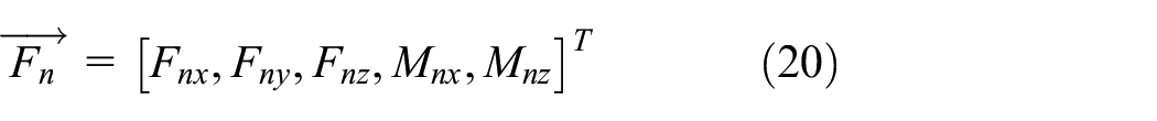
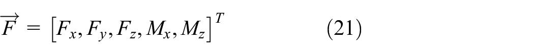
The torsional degrees of freedom can be neglected for the fixed outer ring and the rotating inner ring. Therefore, the inner ring of the ball bearing without cage has five degrees of freedom, and its displacement can be expressed as the sum of axial and angular deflections:
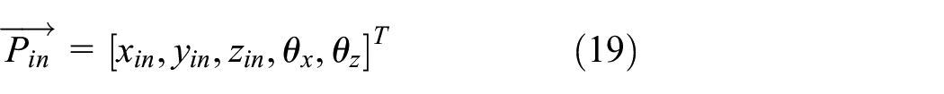
The external force applied on the inner circle can be expressed as:
In accordance with the geometry of the ball bearing without cage and the position of the rolling element, when the ball bearing without cage has a variable diameter raceway, it is possible for a rolling element to be completely positioned in the variable diameter raceway and to separate from the inner ring. The contact force between the rolling element and the inner ring can be expressed as follows:
Therefore, the expression of contact force between Z roller and inner ring is:

The displacement and angular deflection equation of inner ring of ball bearing without cage is:

The position of the variable diameter raceway has a direct effect on the displacement range of the inner ring along the x-axis and y-axis, and this displacement range is consistent.
This section establishes the mechanical model of the rolling body by analyzing the rolling body’s force when the variable diameter raceway is located in the bearing area and the non-bearing area. The number of rolling bodies under radial load is less when a single variable-diameter raceway is located in the bearing area as opposed to the non-bearing area. This section analyzes the position relationship of two and three local variable raceways in ball bearings without cage where the number of local variable raceways may be odd or even. The distribution of variable-diameter raceways will affect the dynamic behavior of unmaintained ball bearings in various ways. The variable-diameter raceway may have various distribution laws. This paper examines uniform distribution and random distribution. The position relationship between the two variable-diameter raceways is expressed as follows when they are uniformly distributed:

When two ball bearings with variable-diameter raceways and no cages are randomly distributed, their positional relationship need only satisfy the following equation:

There are three variable-diameter raceways in the cageless ball bearing, and when the three raceways are uniformly distributed, the interval between the position angles of each two variable-diameter raceways is

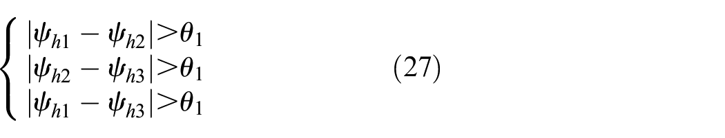
When the three variable-diameter raceways in a ball bearing without cage are randomly distributed, the position relationship between them only needs to satisfy the following equation:
Due to the difficulty in predicting the random distribution of the variable diameter raceway, this paper only considers the uniform distribution of the variable diameter raceway. According to the previous two sections’ theoretical analysis of the shape and position of the variable diameter raceway, the design scheme of the variable diameter raceway parameters consists of nine schemes: a rectangular, shuttle or elliptical variable diameter raceway, two rectangular positions with angular spacing of
The determination of the motion differential equation of a ball bearing without cage
Assuming the ball bearing without cage has k local variable raceways and z rollers, the kinetic energy and potential energy equations of the inner and outer rings, as well as the kinetic energy equation and potential energy equation of z rollers, are substituted into the Lagrange equation to obtain an equation, and the differential equation of the motion of the bearing roller and the inner ring can be obtained.
The differential equation of radial motion of rolling body heart is derived as follows:

The differential equation of x-axis motion of inner ring center is derived as follows:
The differential equation of y-axis motion of inner ring center is:

Formula:

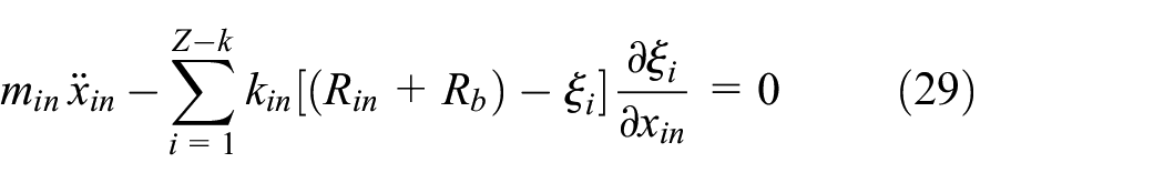
From formula (31):

Deflections to

On the basis of the initial displacement of the center of the roller and the inner ring, the variation of the roller and inner ring’s speed and displacement with time can be determined.
Investigation into the motion stability of ball bearings without cage
To facilitate the comparative analysis of the effect of different shapes of variable diameter raceways on the motion stability of the inner ring and rolling body, this paper uses matlab software to solve differential equations numerically.
The maximum radial displacement of the rolling center of mass caused by rectangular, uniform and elliptical variable diameter raceways is set to 1 mm. Nonetheless, the radial displacement of the rolling centerfold due to the design of spindle and elliptical variable diameter raceways varies over time. Consequently, based on the structural parameter equations of rectangular, spindle, and elliptical variable diameter raceways, it can be assumed that the radial displacement of the rolling body at a given position is 1, 0.64, and 0.8 mm, respectively, for rectangular, spindle, and elliptical variable diameter raceways.
When the local variable diameter raceway is in the bearing area, the initial position of the inner ring center is (0, 0); when it is in the non-bearing area, the initial position is (0, 0.5), and the solution time is set to 0.1 s. The nonlinear differential equation group is solved using the Runge-Kutta method, and the velocity and displacement of the rolling centroid and the center of the inner ring with a solution time greater than the specified time are output. By solving the differential equation of the inner ring’s motion, the center’s velocity and displacement along the x- and y-axes can be determined. The velocity-displacement phase diagram of the inner ring center along the x- and y-axes is depicted for various outer ring local variable diameter raceway parameters.
In the bearing area of the outer ring of a ball bearing without a cage is a single variable-diameter raceway, and the velocity-displacement phase diagram of the inner ring center along the x and y axes differs depending on the shape of the variable-diameter raceway. Figure 3 depicts the velocity-displacement phase diagram of the inner ring center along the x axis and y axis when a single rectangular variable diameter raceway is located in the bearing area. Figure 3(a) depicts the phase diagram of the inner ring center along the x axis, and Figure 3(b) depicts the phase diagram along the y axis.

The inner ring phase diagram of single rectangular raceway located in the bearing zone: (a) x-axis and (b) y-axis.
The velocity-displacement phase diagrams of the inner ring center along the x-axis and y-axis are closed oval curves with a certain width, as shown in Figure 3. The velocity fluctuation range of the inner ring center along the x axis is depicted in Figure 3(a) as −1.5 × 10⁴– 1.5 × 104 μm/s, while the displacement variation range is 0-2 μm . The velocity fluctuation range of the inner ring center along the y axis is 8000–8000 μm, and the displacement variation range is 0.5–1.5 μm, as shown in Figure 3(b). Figure 3(a) and (b) demonstrate that the width of the curve along the y axis of the phase diagram of the inner ring center is slightly greater than that along the x axis. Figure 4 depicts the velocity–displacement phase diagram of the inner circle center along the x- and z-axes when the single shuttle deformation path is located in the bearing area. Figure 4(a) depicts the phase diagram of the inner ring center along the x axis, and Figure 4(b) depicts its phase diagram along the y axis.

The inner ring phase diagram of single shuttle raceway located in the bearing zone: (a) x-axis and (b) y-axis.
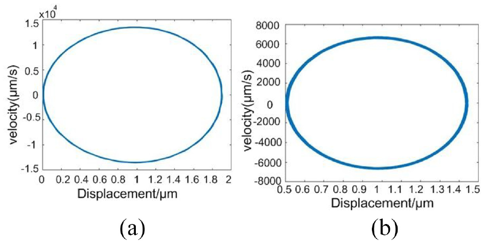
The velocity-displacement phase diagram of the inner ring center along the x-axis and y-axis directions is very regular and a closed oval curve with a certain width, as shown in Figure 4. However, the variation range of velocity and displacement is obviously different from that of a single rectangular variable diameter raceway located in the bearing area. From Figure 4(a), the velocity fluctuation range of the inner ring center along the x axis is −1.5 × 10⁴ – 1.5 × 104 μm/s, and the displacement fluctuation range is (0 1.9) μm. The velocity fluctuation range of the inner ring center along the y axis is −7000 to 7000 μm/s, while the displacement range is 0.5–1.4 μm. Figure 5 depicts the velocity-displacement phase diagram of the inner ring center along the x- and z-axes when a single elliptical variable diameter raceway is positioned in the bearing area. Figure 5(a) depicts the velocity-displacement phase diagram of the inner ring center along the x axis, and Figure 5(b) depicts the velocity-displacement phase diagram along the y axis.

The inner ring phase diagram of one oval raceway located in the bearing zone: (a) x-axis and (b) y-axis.
Figure 5 demonstrates that the central phase diagram of the inner ring is likewise a closed elliptic curve with a particular width. As shown in Figure 5(a), the velocity variation range is −1.5 × 10⁴ – 1.5 × 104 μm/s, and the displacement variation range is (0 1.9) μm. The velocity variation range is −6000 to 6000 μm/s, and the displacement variation range is 0.5–1.38 μm, as shown in Figure 5(b). When the local variable diameter raceway is located in the bearing area and the non-bearing area, the number of rollers bearing radial load is different; therefore, the position of the local variable diameter raceway must have different effects on the y-axis motion of the inner ring. In the non-bearing region of the ball bearing without cage, a single variable-diameter raceway is positioned. Figures 6 to 8 depict the velocity-displacement phase diagram of the inner ring center along the y-axis when the shape of the variable diameter raceway varies. Figure 6 depicts the velocity-displacement phase diagram of the inner ring center along the y axis when a single rectangular variable-diameter raceway is positioned in the non-bearing area.

The inner ring phase diagram of single rectangular raceway located in the bearing section.

The inner ring phase diagram of single shuttle raceway located in the bearing section.

The inner ring phase diagram of single oval raceway located in the bearing section.
The velocity-displacement phase diagram of the inner ring center along the y axis is depicted in Figure 6 as a closed elliptic curve with a specific width. The velocity variation range is −1.5 × 10⁴ – 1.5 × 104 μm/s, while the displacement variation range is 0–2 μm. Figure 7 depicts the phase diagram of the inner ring’s center along the axial direction when the single shuttle deformation path is located in the non-bearing region.
Figure 7 demonstrates that the phase diagram of the inner ring center along the y axis is also an elliptical curve with a certain width, where the velocity fluctuation range is −1.5 × 10⁴ – 1.5 × 104 μm/s and the displacement range is (0 1.9) μm. Figure 8 depicts the velocity-displacement phase diagram of the inner ring’s center along the y axis when the single elliptical variable diameter raceway is located in the non-bearing region.
Figure 8 demonstrates that the velocity-displacement phase diagram of the inner ring center is also an elliptical curve, with a velocity fluctuation range of −1.5 × 10⁴ – 1.5 × 104 μm/s and a displacement variation range of (0 1.9) μm. The differential equations of motion of unsupported ball bearings with two and three variable-diameter raceways are solved in order to examine the effect of the number of variable-diameter raceways on the inner ring motion of unsupported ball bearings. When the outer ring has two variable-diameter raceways with angular spacing, one in the bearing area and the other in the non-bearing area, the velocity-displacement phase diagram is depicted in Figures 9 to 11. Figure 9 depicts the velocity-displacement phase diagram of the inner ring center along the x- and z-axes when the outer ring has two rectangular variable-diameter raceways. Figure 9(a) depicts the phase diagram of the inner ring center along the x-axis, and Figure 9(b) depicts the phase diagram along the y-axis.

The inner ring phase diagram of two rectangular variable diameter raceways: (a) x-axis and (b) y-axis.

The inner ring phase diagram of two shuttle variable diameter raceways: (a) x-axis and (b) y-axis.
The inner ring phase diagram of two oval variable diameter raceways: (a) x-axis and (b) y-axis.
Figure 9(a) demonstrates that the phase diagram of the inner ring center along the x axis is a closed circular curve, the velocity fluctuation range is −1.5 × 10⁴ – 1.5 × 104 μm/s, and the displacement change range is (0 2.3) μm. The phase diagram of the inner circle center along the y-axis is also a closed and highly regular elliptical curve, as shown in Figure 9(b). The range of velocity variation is 8000–8000 μm/s, and the range of displacement variation is 0.5–1.6 μm. Figure 10 depicts the velocity–displacement phase diagram of the inner ring center when the outer ring of a ball bearing without cage has two shuttle deformation raceways. The x-axis phase diagram of the center of the inner ring, as shown in Figure 10(a), and its y-axis phase diagram, as shown in Figure 10(b). The velocity–displacement phase diagrams of the inner ring center along the x-axis and y-axis are closed oval curves with a certain width, as shown in Figure 10(a) and (b). In comparison to the phase diagrams for the y-axis and x-axis directions, the width of the oval curve is slightly greater.
Figure 10(a) demonstrates that when the outer ring has two spindle-shaped raceways, the velocity fluctuation range of the inner ring center along the x-axis is −1.5 × 10⁴ – 1.5 × 104 μm/s and the displacement variation range is (0 2) m. The velocity fluctuation range of the inner ring center along the y-axis is 7000–7000 μm/s, and the displacement variation range is 0.5–1.5 μm, as shown in Figure 10(b). Figure 11 depicts the velocity-displacement phase diagram of the inner ring center when the outer ring of a ball bearing without a cage has two elliptical variable-diameter raceways. Figure 11(a) depicts the velocity-displacement phase diagram of the inner ring center along the x axis, and Figure 11(b) depicts the velocity-displacement phase diagram along the axis. The velocity-displacement phase diagram of the inner ring center along the x- and z-axes is an elliptical curve with a certain width, and the width of the curve in the y-axis direction is slightly larger than that in the x0-axis direction (Figure 11(a) and (b)).
The phase diagram velocity fluctuation range of the inner ring center along the x axis is −1.5 × 10⁴ – 1.5 × 104 μm/s and the displacement range is (0 2) μm when the outer ring has two elliptical raceways. Figure 11(b) reveals that the velocity fluctuation range of the phase diagram along the y-axis of the inner ring center is −7000 to 7000 μm/s and the displacement range is 0.5–1.45 μm. To optimize the number of variable-diameter raceways, this section must solve the problem that the outer ring of the ball bearing without cage contains three variable-diameter raceways with an angular spacing of 2/3, and one variable-diameter raceway is located in the bearing area. When the other two variable-diameter raceways are located in the non-bearing region, the velocity and displacement of the inner ring center are obtained, as well as the inner ring’s corresponding phase diagram. The velocity-displacement phase diagram of the inner ring center along the x- and z-axes is depicted in Figure 12(a) and (b) when the outer ring of the ball bearing without cage has three rectangular variable diameter raceways.

The inner ring phase diagram of three rectangular variable diameter raceways: (a) x-axis and (b) y-axis.
Figure 12(a) shows that the phase diagram of the inner ring center along the x-axis is a closed circular curve with a specific width, that the velocity fluctuation range is −1.5 × 10⁴ – 1.5 × 104 μm/s, and that the displacement variation range is (0 2.3) μm. As shown in Figure 12(b), the phase diagram of the inner circle center along the y-axis is an elliptical curve with a specific width, its velocity fluctuation range is 8000–8000 μm/s, and its displacement variation range is 0.5–1.6 μm. Figure 13 depicts the velocity–displacement phase diagram of the inner ring center for cageless ball bearings with three shuttle deformation raceways on the outer ring. Figure 13(a) depicts the velocity-displacement phase diagram along the x axis of the inner ring center, while Figure 13(b) depicts the velocity-displacement phase diagram along the y axis. As shown in Figure 13(a) and (b), the velocity–displacement phase diagrams of the inner ring center along the x- and z-axes are closed oval curves with a certain width. The oval curve has a slightly larger width than the y-axis and x0-axis phase diagrams.

The inner ring phase diagram of three shuttle variable diameter raceways: (a) x-axis and (b) y-axis.
Figure 13(a) depicts the velocity fluctuation range of the inner ring center along the x axis as −1.5 × 10⁴ – 1.5 × 104 μm/s, while the displacement range is (0 2.3) μm. The range of velocity variation along the y axis is −8000 to 8000 μm/s, while the range of displacement variation is 0.5–1.6 μm. Figure 14 depicts the velocity-displacement phase diagram of the inner ring center when the outer ring of a ball bearing without a cage has three elliptical variable diameter raceways. Figure 14(a) depicts the velocity-displacement phase diagram along the x axis of the inner ring center, and Figure 14(b) depicts the phase diagram along the y axis of the inner ring center. Figure 14(a) and (b) show that the velocity-displacement phase diagram of the inner ring center along the x- and z-axes is closed and has a particular width. The elliptic curve has a larger width compared to the x0-axis direction phase diagram.

The inner ring phase diagram of three oval variable diameter raceways: (a) x-axis and (b) y-axis.
Figure 14(a) demonstrates that the velocity fluctuation range of the inner ring center along the x axis is −1.5 × 10⁴ – 1.5 × 104 μm/s and the displacement fluctuation range is (0 2.3) μm. Figure 14(b) demonstrates that the velocity fluctuation range of the inner ring center along the y axis is −1 × 10⁴ to 1 × 104 μm/s and the displacement fluctuation range is 0.5–1.7 μm.
After obtaining the fluctuation range of the inner circle center, this paper obtains the radial velocity and displacement of the rolling body center by solving the differential equation of rolling body motion, and draws the phase diagram of the radial velocity displacement of the rolling body center when the rolling body is at different positions, as shown in Figures 15 to 18. The phase diagram of the rolling element located on the raceway of the conventional outer ring is shown in Figure 15.

The phase diagram of the rolling body in conventional outer raceway.
The phase diagram of the rolling body in rectangular variable diameter raceway.

The phase diagram of the rolling body in shuttle variable diameter raceway.

The phase diagram of the rolling body in oval variable diameter raceway.
It can be seen from Figure 15 that the velocity displacement phase diagram of the rolling body located in the conventional outer race raceway of the cage free ball bearing is a number of closed curves, and its velocity fluctuation range is −8 × 10⁷ to 8 × 107 μm/s, the displacement range is −100 to 100 μm.
The phase diagram of the rolling element located in the rectangular variable diameter raceway is shown in Figure 16.
It can be seen from Figure 16 that the phase diagram of the rolling body located in the rectangular variable diameter raceway in the cage free ball bearing is a number of closed circular curves, and its speed fluctuation range is −5 × 10⁷ to 5 × 10⁷ μM/s, the displacement range is −100 to 100 μm.
The phase diagram of the rolling element when it is located in the shuttle reducing raceway is shown in Figure 17.
It can be seen from Figure 17 that the velocity displacement phase diagram of the rolling element in the cage free ball bearing is a number of closed elliptic curves, with a velocity fluctuation range of −3 × 10⁷ to 3 × 107 μm/s, displacement variation range is –70 to 60 μm.
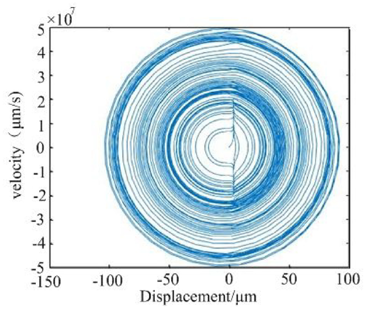
The phase diagram of the rolling element when it is located in the elliptical variable diameter raceway is shown in Figure 18.
It can be seen from Figure 18 that the rolling body velocity displacement phase diagram is a number of closed elliptic curves, and its velocity fluctuation range is −3 × 10⁷ to 3 × 107 μm/s, displacement variation range is −70 to 60 μm.
According to the nonlinear motion theory, when the velocity displacement phase diagram of the inner ring of the cage free ball bearing is a closed curve, the inner ring motion is single period or double period motion; when the phase diagram is a curve band with a certain width, the inner circle motion is quasi periodic; when the curve in the phase diagram does not repeat and fills a part of the space, the inner circle motion is chaotic.
By comparing and analyzing Figures 3 to 5, it can be seen that the velocity displacement phase diagrams of the inner race of cage free ball bearings with three different shapes of variable diameter raceways along the x and y axes are closed elliptic curves with a certain width, indicating that the inner race motion is stable quasi periodic motion. It can be seen from Figures 3(a), 4(a) and 5(a) that the speed displacement phase diagram of the inner ring of cage free ball bearing with three different shape variable diameter raceways is almost the same along the x-axis direction; it can be seen from Figures 3(b), 4(b) and 5(b) that the speed range and displacement range of the inner ring of the cage free ball bearing with a single shuttle or oval variable diameter raceway are smaller than those of the cage free ball bearing with a single rectangular variable diameter raceway in the y-axis direction, indicating that when the number of variable diameter raceways is one and they are located in the bearing area, the shuttle or oval variable diameter raceway makes the inner ring vibrate less and has better motion stability.
It can be seen from the comparative analysis of Figures 6 and 8 that when the number of variable diameter raceways is one and they are located in the non bearing area, the influence of the shape of variable diameter raceways on the inner race movement. The speed variation range of the center of the inner ring of cage free ball bearings with rectangular, shuttle, or elliptical variable diameter raceways along the x-axis direction is basically consistent with the displacement variation range and the y-axis velocity variation range. However, it can be seen from Figures 6, 7 and 8 that when a single variable diameter raceway is located in the non bearing area, compared with the rectangular variable diameter raceway, the spindle or oval variable diameter raceway has a smaller displacement range along the y-axis direction of the inner ring center. Therefore, when the number of variable diameter raceways is one and the raceways are located in the non load bearing area, the shuttle or oval variable diameter raceways make the inner race of cage free ball bearings vibrate less and have better motion stability.
From Figure 9 to Figure 11, it can be seen that the velocity displacement phase diagram of the center of the inner ring of the cage free ball bearing with two rectangular, shuttle shaped and elliptical variable diameter raceways along the x and y axes is a closed curve, and the movement of the inner ring has obvious periodicity. Compared with the cage free ball bearing with two shuttle shaped or elliptical variable diameter raceways, the speed variation range of the inner race center along the x-axis direction is basically the same, but the displacement variation range of the inner race center along the x-axis direction, the velocity variation range of the y-axis direction and the displacement variation range are smaller. Therefore, when the number of variable diameter raceways is two and one is located in the load bearing area and the other is located in the non load bearing area, the shuttle or oval variable diameter raceways make the inner ring of the cage free ball bearing vibrate less and have better motion stability.
By comparing and analyzing Figures 12 to 14, it can be seen that when the number of variable diameter raceways is three and one is located in the bearing area and two are located in the non bearing area, the velocity displacement phase diagram along the x-axis direction of the inner ring center is a closed circular curve, and the velocity displacement phase diagram along the y-axis direction is a closed elliptic curve with a certain width. Compared with the bearing with three rectangular or shuttle shaped variable diameter raceways, the speed variation range and displacement variation range of the inner race center along the x-axis direction are basically the same, but the speed variation range and displacement variation range of the inner race center along the y-axis direction are slightly smaller. Therefore, when the number of variable diameter raceways is three and one is located in the bearing area and two are located in the non bearing area, the rectangular or shuttle variable diameter raceways make the inner ring of the cage free ball bearing vibrate less and have better motion stability.
In order to improve the stability of the inner ring center movement, the location of the variable diameter raceway is preferred. By comparing Figure 3 with Figure 6, Figures 4 with Figure 7, Figures 5 with Figure 8, it can be seen that when the number of variable diameter raceways is one and the shape is the same, when the variable diameter raceway is located in the bearing area, the speed and displacement change range of the inner ring along the y-axis direction is smaller than when it is located in the non bearing area, the inner ring movement is more periodic and more stable. Therefore, from the perspective of the motion stability of the inner ring, the optimal result of the location of the variable diameter raceway is that there is a variable diameter raceway located in the bearing area.
According to the above analysis on the numerical solution results of the differential equation of inner ring motion, although the inner ring motion of the cage free ball bearing is always quasi periodic, the variation range of the inner ring speed and displacement of the cage free ball bearing with different variable diameter raceway parameters is not the same. If the number of variable diameter raceways is one or two, and there is a variable diameter raceway located in the bearing area, then when the variable diameter raceway is shuttle shaped or elliptical, the motion stability of the inner race of the cage free ball bearing is better. If there are three variable diameter raceways and one variable diameter raceway is located in the bearing area, the stability of the inner ring of the cage free ball bearing is better when the variable diameter raceway is rectangular or shuttle shaped.
It can be seen from Figures 15 to 18 that the radial displacement velocity phase diagram of the rolling mass center is not repeated and is full of phase space, so the motion of the rolling mass is chaotic. The speed variation range of the rolling body in the variable diameter raceway is much smaller than that in the conventional outer ring raceway. The reason is that the rolling body enters the variable diameter raceway from the conventional outer ring raceway and leaves the inner ring, reducing its kinetic energy. By comparing the radial speed and displacement range of the rolling body in Figures 15 to 18, it can be seen that the rolling body located in the shuttle or oval variable diameter raceway has a higher stability. Therefore, from the point of view of rolling body motion stability, the shape of variable diameter raceway is shuttle or oval.
Preparation and test of partial outer ring variable diameter raceway cageless bearings
To verify the rationality of theoretical preferences of reducer raceway parameters, this section will conduct vibration measurement tests of cage-free ball bearings, use wavelet soft threshold function to denoise experimentally measured vibration signals, compare and analyze the influence of the reducer raceway shape on the vibration of the cage-free ball bearing system at different speeds, and establish the relationship between the reducer raceway shape and cage-free ball bearing system vibration. This has important implications for the study of the structural optimization design direction and practical application conditions of cage-free ball bearings.
Individual rectangular, shuttle, and elliptical reducer races were machined on the outer ring of cageless ball bearings according to the reducer race shapes designed in Chapter 2, including rectangular, shuttle, and elliptical.
Due to the unique design of the local reducer raceway in this paper, the method of machining is EDM. In order to compare the effect of the reducer raceway shape on the bearing vibration more clearly, the length, width, and maximum depth of all three reducer raceway shapes are the same: 11.5, 3.5, and 1 mm, respectively. Figure 19 depicts specimen 1 as a completed single rectangular reducer raceway bearing outer ring.

The outer ring of cage free bearing with single oval variable diameter raceway: (a) rectangular partial reducer raceway, (b) diamond variable diameter raceway, and (c) oval variable diameter raceway.
The three bearing outer rings after EDM were assembled into three cage free ball bearings, which were tested on a T10-60 model bearing tester to measure the vibration signals of the cage free ball bearings under actual working conditions.
The photograph of the model T10-60 bearing testing machine, as shown in Figure 20, mainly includes the table, bed, radial loading assembly, axial loading assembly, driving spindle, vibration sensor and amplifier, test bearing and auxiliary bearing, etc.

Cage free ball bearings testing machine: (a) left view and (b) right view.
A schematic diagram of how to mount the test piece of a cageless ball bearing is shown in Figure 21.

The installation method of cage free ball bearings test piece.
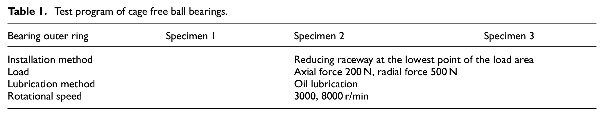
In this paper, in order to investigate the effect of variable diameter raceway shape and inner ring speed on the vibration of cageless ball bearing system, the designed test program is shown in Table 1.
Test program of cage free ball bearings.
Assemble the test pieces into a cageless ball bearing as shown in Figure 22. Set the outer ring of the cageless ball bearing to be fixed and the inner ring to be rotated, and measure the vibration signal when the bearing is running smoothly.

The cage free ball bearing.
The vibration signals generated by the three test bearings at the inner ring speed of 3000 and 8000 r/min were obtained through the test, and the soft threshold method in wavelet analysis was used to denoise the vibration signals.
When the inner ring speed is 3000 r/min, the original signal of vibration of a single rectangular reducer raceway bearing located in the bearing area, the signal after soft threshold denoising process, as shown in Figure 23(a) and (b), and the original signal of vibration of a single shuttle reducer raceway bearing located in the bearing area, the signal obtained by denoising process, as shown in Figure 24(a) and (b).
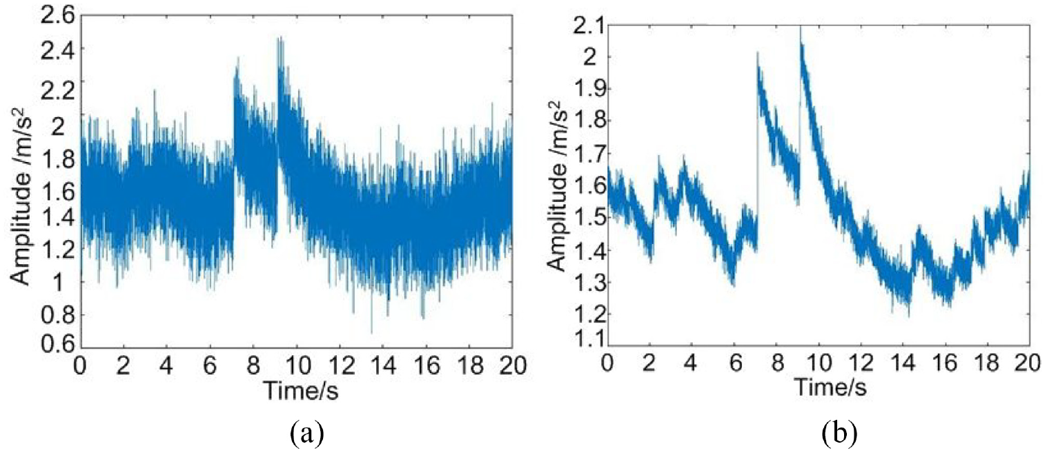
The original vibration signal of rectangular variable diameter cable duct and the signal processed by wavelet: (a) original signal and (b) signal processed by wavelet.
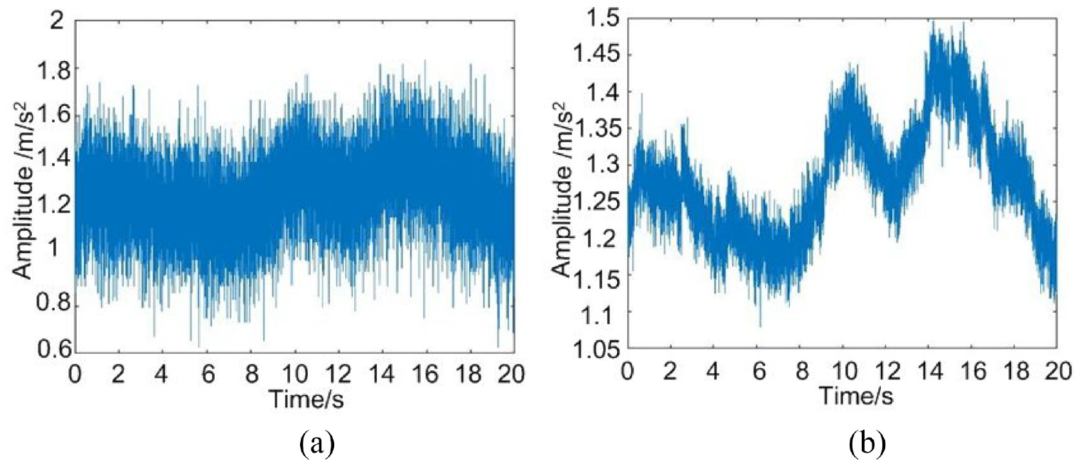
The original vibration signal of shuttle variable diameter raceway and the signal after wavelet processing: (a) original signal and (b) signal Processed by wavelet.
When the inner ring speed is 3000 r/min, with a single elliptical reducer raceway located in the bearing area without cage ball bearing vibration raw signal, soft threshold denoising processing to obtain the signal, as shown in Figure 25(a) and (b).
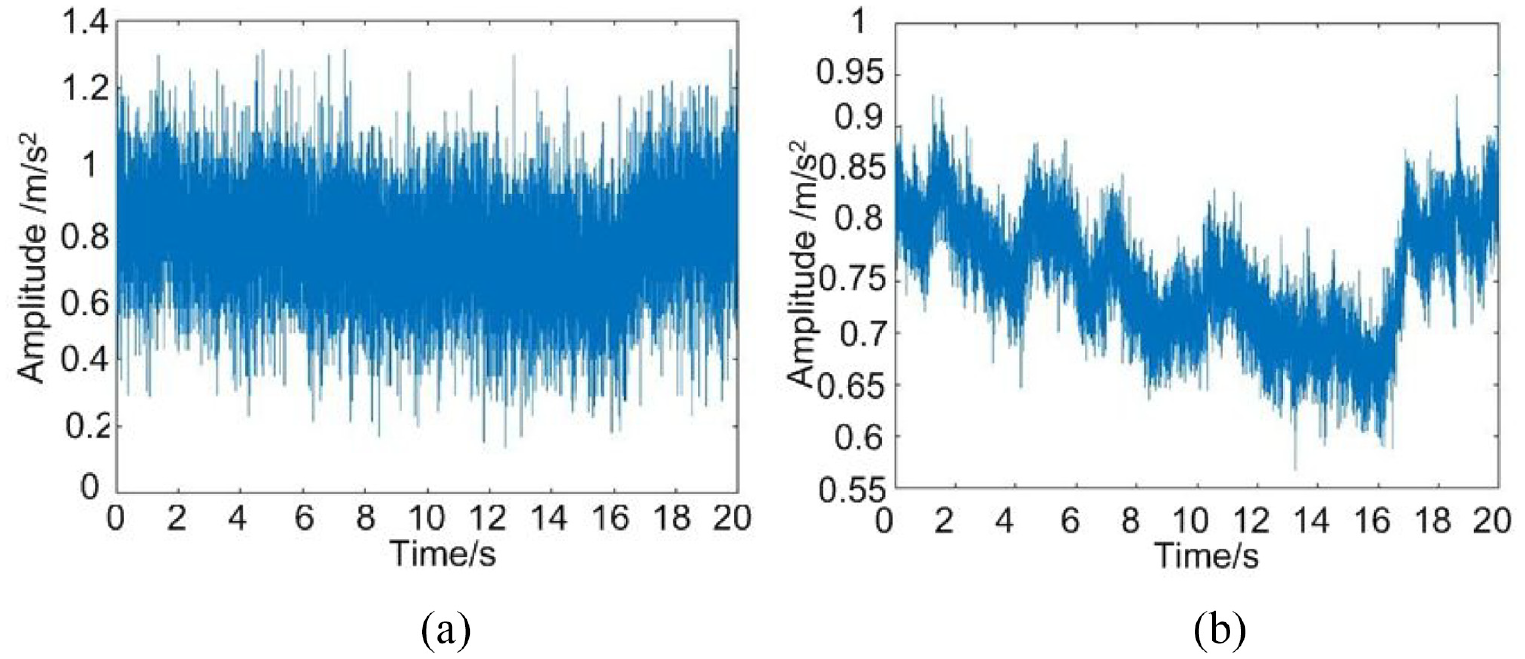
The original vibration signal of elliptic variable diameter raceway and the signal after wavelet processing: (a) original signal and (b) signal processed by wavelet.
From Figure 23(b), it can be seen that the vibration signal amplitude range is 0.6–2.6 m/s2 for the rectangular shaped raceway without cage ball bearing with a single located in the load carrying area. from Figure 24(b), it can be seen that the vibration signal amplitude range is 1.05–1.5 m/s2 after denoising when the shuttle shaped raceway without cage ball bearing with a single located in the load carrying area. From Figure 25(b), it can be seen that the vibration signal amplitude range is 0.55–1 m/s2 for the elliptical shaped raceway without cage ball bearing with a single located in the load carrying area. The vibration signal amplitude of the elliptical reducer raceway without cage ball bearing located in the bearing area is 0.55–1 m/s2.
Comparing the vibration amplitude range of the three types of cage free ball bearings after denoising reveals that the cage free ball bearing with a single elliptical reducer race located in the bearing area has the smallest vibration amplitude, while the cage free ball bearing with a shuttle-shaped reducer race has the second-largest vibration amplitude. Consequently, of the three shapes of rectangular, shuttle, and elliptical raceways, the cage free ball bearing with an elliptical raceway has the lowest vibration when the inner ring speed of the cage free ball bearing is 3000 r/min and the single raceway is located in the load bearing area. This experimental result confirms the correctness of the inner ring and rolling element motion stability analysis results in Chapter 3 and the veracity of the simulation results in Chapter 4.
In order to investigate the influence of the inner ring speed on the vibration characteristics of the cage free ball bearing, a test with an inner ring speed of 8000r/min was also conducted.
The original signal of the vibration of the rectangular reducer raceway cageless ball bearing with a single located in the bearing area, and the signal obtained by soft threshold denoising processing, are depicted in Figure 26(a) and (b), respectively, when the inner ring speed is 8000 r/min.

Original vibration signal of rectangular variable diameter cable duct and signal after wavelet processing: (a) original signal and (b) signal processed by wavelet.
From Figure 26(b), it can be seen that the vibration amplitude range of the rectangular reducer raceway without cage ball bearing with a single located in the load bearing area is 4.9–5.9 m/s2.
The original signal of vibration of the shuttle reducer raceway without cage ball bearing with a single located in the bearing area and the signal obtained by soft threshold denoising processing are depicted in Figure 27(a) and (b)), respectively, when the inner ring speed is 8000 r/min.

The original vibration signal of shuttle variable diameter raceway and the signal after wavelet processing: (a) original signal and (b) signal processed by wavelet.
From Figure 27(b), it can be determined that the vibration amplitude range of the shuttle-shaped variable raceway cage free ball bearing with a single located in the load-bearing region is between 3 and 5.5 m/s2.
The original signal of the vibration of the elliptical reducer raceway cageless ball bearing with a single located in the load bearing area and the signal obtained by soft threshold denoising processing are depicted in Figure 28(a) and (b) when the inner ring speed is 8000 r/min.

The original vibration signal of elliptic variable diameter raceway and the signal after wavelet processing: (a) original signal and (b) signal processed by wavelet.
From Figure 28(b), the vibration amplitude range of an elliptical reducer raceway without cage ball bearing with a single located in the bearing area is 2–2.8 m/s2.
By comparing the original signal to the soft threshold denoising processing signal, it can be seen that the soft threshold denoising processing better retains the detailed portion of the vibration signal, that the calculation speed is quick, and that the denoising effect is good, as Table 2 demonstrates the wavelet soft threshold denoising effect index.
Denoising effect index of wavelet soft threshold method.

Comparing Figures 26 to 28, it can be determined that when the speed of the cage free ball bearing’s inner ring is 8000 r/min, when the number of reducer raceways is one, and when the position is in the bearing area, the vibration amplitude of the cage free ball bearing with elliptical reducer raceway is the smallest, the vibration amplitude of the cage free ball bearing with shuttle reducer raceway is larger, and the vibration ampli The largest value is the amplitude.
Comparing Figure 23 with Figure 26, Figure 24 with Figure 27, and Figure 25 with Figure 28, it can be seen that when the shape of the local reducer raceway is the same, the inner ring speed is 8000 r/min rather than 3000 r/min, and the cage free ball bearing has a much larger vibration amplitude range. Therefore, cage-free ball bearings with a single reducer raceway in the load-bearing area are better suited for applications where the inner ring speed is relatively low.
In conclusion, when the inner ring speed of a cage-free ball bearing is different, the shape of the local reducer raceway has the same effect on the bearing’s vibration amplitude. To reduce the vibration of the ball bearing without cage, the outer ring reducer raceway parameters should be chosen as a single oval local reducer raceway in the load-bearing area.
Discussion
In this paper, only one processing method for a local variable diameter raceway is proposed, and the processing schemes for two and three local variable diameter raceways must be studied further.
Only the stability of a ball bearing without a cage under dry friction conditions is considered in this paper; the motion stability of the rolling element and inner ring under lubrication conditions requires additional analysis and research.
Conclusions
In this paper, the local reducer raceway parameters of the outer ring of the cageless ball bearing are designed, and the energy-based motion state of the cageless bearing’s components is analyzed. By comparing the motion stability of the inner ring and rolling body of cage-free ball bearings under different reducer raceway parameters, the structural parameter equations of rectangular, spindle, and elliptical reducer raceways are established, as well as the geometric parameters of the local reducer raceways of various shapes. It is determined that the number of rolling elements in the bearing area of the reducer raceway is one fewer than the number of rolling elements in the non-bearing area. The inner ring displacement equation was established, and the center displacement variation along the axial and radial directions was determined. The equation of rolling center displacement was established, laying the groundwork for the subsequent establishment of the energy equation, and the range of spherical center distance of adjacent rolling bodies without contact was determined. Separate differential equations of motion for the rolling body and the inner ring were established, and the velocity-displacement phase diagrams of the rolling body’s and inner ring’s centers were obtained. It was determined how the reducer raceway parameters affected the motion stability of the rolling body and the inner ring. The vibration test of three shapes of single reducer raceway ball bearings under various working conditions has been completed, and the elliptical reducer raceway bearing has been determined to have the lowest vibration.
Next, we will study the discrete performance of the discrete groove with oil, establish the differential equation of motion of the bearing roller under the conditions of oil starvation, semi starvation and full oil, and take into account the characteristics of the discrete groove that may store oil and the changes in the contact form.
Footnotes
Appendix
Handling Editor: Chenhui Liang
Declaration of conflicting interests
The author(s) declared no potential conflicts of interest with respect to the research, authorship, and/or publication of this article.
Funding
The author(s) disclosed receipt of the following financial support for the research, authorship, and/or publication of this article: This work supported by Research Program supported by National Natural Science Foundation of China (Research on the automatic discrete mechanism of ceramic ball bearings with local variable speed surface without cage), China.