
Abstract
In this paper, the passivity-based boundary controller for the vibration suppression of the flexible beam is studied. The undamped shear beam model is used as a beam model. The beam is a parameter-distributed system represented by partial differential equations (PDEs). This technique uses the energy principle for control design by exploiting the passivity property of the beam. The storage or energy function of the beam is first introduced and then used to determine the passivity-based controller. The passivity of the system is proven using direct integration. The feedback system is proven in the sense of finite-gain
Keywords
Introduction
Vibration control of beams is essential in many applications such as robotic arms, space structures, etc. Beam models are continuous systems, also known as distributed systems. Therefore, the model will be represented by partial differential equations. The state variable is the function of space and time.
The flexible beams are lightweight and consume less energy. However, the beams move at varying speeds in applications such as the industrial robotic arm, so an elastic vibration is unavoidable. Therefore, sometimes it has to wait until the vibration subsides before the next task can be done. Consequently, it is counterproductive for the industry.
The Euler-Bernoulli beam is the basic beam model consisting of the bending moment and the lateral displacement terms. If the shear deformation is included in this beam model, the model will become a shear beam. But if the rotational inertia is added instead, a Rayleigh beam is obtained. Timoshenko beam incorporates all beam properties. The detailed derivations of the beam models mentioned above were investigated in Han et al. 1
Historical development of controls for PDE-governed systems was presented by Lasiecka. 2 This paper focused on the problems with point and boundary control. The recent advancements in the field of distributed parameter systems can be found in the study of Padhi and Ali. 3
Kim and Renardy 4 investigated the uniform stabilization of the Timoshenko beam. It was a boundary damper feedback at the beam tip. Luo et al. 5 employed a direct shear force to suppress the vibration of the rotational joints of the robot. The proportional integral controller with a shear force feedback gave good results.
Morgul 6 investigated the fixed-free Timoshenko beam. The controller was applied directly at a vibrating end of the beam. Lyapunov functional, based on the beam system’s energy, was used for stability proof. The control law suppressed the vibration exponentially and uniformly.
The backstepping boundary control scheme was proposed by Krstic et al.7–9 The authors investigated the control problem of the shear beam. The beam model was converted into a known target system and the state variable was changed. The backstepping technique was employed for the design. Since the set-up was anti-collocated, the observer was needed.
The vibration control of the Euler-Bernoulli beam was investigated by Smyshlyaev et al. 10 The beam was re-expressed in the form of the Schrodinger equation so that the backstepping technique could be applied. The controller was applied at the end of the beam by which the opposite end was the sliding end.
Guo and Jin 11 considered the control problem of the Euler-Bernoulli beam. The original beam model was first converted into a coupled heat-like system in the design process. Then, the backstepping method was used to transform this converted beam into an exponentially stable target system.
In the paper of He et al., 12 the vibration suppression of the Euler-Bernoulli beam with the boundary output control was proposed. For the stability and control design, a barrier Lyapunov function was employed to restrain the constraint violation. The active control was designed to treat the system parameter uncertainties.
Dog̃an and Morgul 13 studied the vibration control of a rotating shear beam employing the coordinate transformation concept and backstepping techniques for the control scheme and observer designs. The vibration control and set-point regulation gave good results.
He et al. 14 considered the control problem of the Timoshenko beam. The disturbance varied spatiotemporally. The control scheme was based on Lyapunov’s direct method, and the observer was designed to reduce external disturbance. The states were proven to be uniformly ultimately bounded.
Ortega et al. 15 presented the control principle using the energy concept. They also gave the concepts of passivity and energy shaping in controller design.
In the paper of Matsuno and Murata, 16 the passivity of mechanical systems was considered. The control scheme was designed using the Lyapunov function. The controller was in the form of the PI control plus a strain feedback control law. The system’s stability was proven.
Fard 17 investigated the boundary control of the Euler-Bernoulli beam. The control scheme was designed with the defined Lyapunov function. The controller was applied at the end of the beam. Furthermore, since the model PDE was treated directly, the control spill-over problem was avoidable.
Sasaki et al.18,19 studied the vibration suppression of the Timoshenko beam using the passivity property. However, since the controller was poorly tuned, the neural network training algorithm had to perform the gain tuning.
The control of vibration of beams subjected to moving loads was studied by Younesian et al. 20 As a result, the so-called optimal tuned mass damper (TMD) was proposed. The sequential quadratic programming method was used to find the optimal frequency and damping ratio. The simulation of an actual railway bridge with a moving train was conducted to verify the method’s effectiveness.
Gong et al. 21 investigated the suppression of the vertical vibration of a railway car body. Green’s function was used for the study. The proposed passive control was mounted near the car body center.
In the last two papers, the controllers were applied at the beam body, unlike the controller proposed in this article that is applied at the system’s boundary.
The boundary control for a flexible marine risers was investigated by He et al. 22 The vessel dynamics were also included in the model. Lyapunov’s direct method was used for proving.
Zhao et al. 23 designed the robust adaptive boundary control for a marine riser. The system under the study was subject to nonlinearity and unknown disturbance. The controller restrained the vibration offset and eliminated the effects of the nonlinearities.
Liu et al. 24 employed the backstepping technique for the controller design for a flexible aerial refueling hose. The closed-loop stability was proven, and the proposed control scheme was also compared with the Proportional-Derivative (PD) control.
In this article, the vibration control of the flexible beam is investigated. The controller is designed using an energy principle, not a signal processing perspective. The storage function, which is the system’s energy function, is first introduced and then employed for controller design. The feedback system is proven for finite gain
The paper is organized as follows: the mathematical model of the undamped shear beam is shown in Section “Mathematical model.” The controller design is in Section “The passivity-based boundary control design” and the PDE solving using finite difference equation is explained in Section “Numerical calculation.” The implementation and performance of the controller are shown and discussed in Section “Results and discussion.” The study on the parameter changes is in Section “Effect of system and control parameter changes.” The conclusion is presented in Section “Conclusion.” In Appendix A, the proof of
The main contributions are: (1) This technique incorporates the energy principle, not the signal processing perspective in control, by defining the storage function of the system and proving the passivity using direct integration. (2) The sensing and the actuation are collocated, so the state observer is unnecessary. (3) The controller is applied at the beam end, so the beam domain (body) is intact, which is implementable in applications. (4) Since the original beam model PDEs are dealt with directly without model reduction, the control spill-over problem is avoidable.
Mathematical model
To perform the passivity-based controller design, the shear beam can be expressed in the form of a wave equation coupling with a second-order-in-space ODE7–9 as follows,


where the subscripts

Beam model with a sliding base.
Apply Newton’s second law to the sliding base with the beam end attached, yielding the following equation of motion,

where
On the left-hand side of (3), the first term is the inertia of the sliding base, and the square-bracketed term is the shear force of the beam acting on the sliding base.
The boundary conditions of the free end and the fixed end 25 are as follows,


The physical meanings of the boundary conditions are as follows: from (4) and (5) indicate that the shear force and bending moment are zero at the free end
Passivity-based boundary control design
The boundary controller will be designed using the passivity of the beam in this section. First, the following controller is proposed,

where
From now on, we will write only

which represents the energy of the beam and the sliding base at time

Substituting (1) into (10), we get
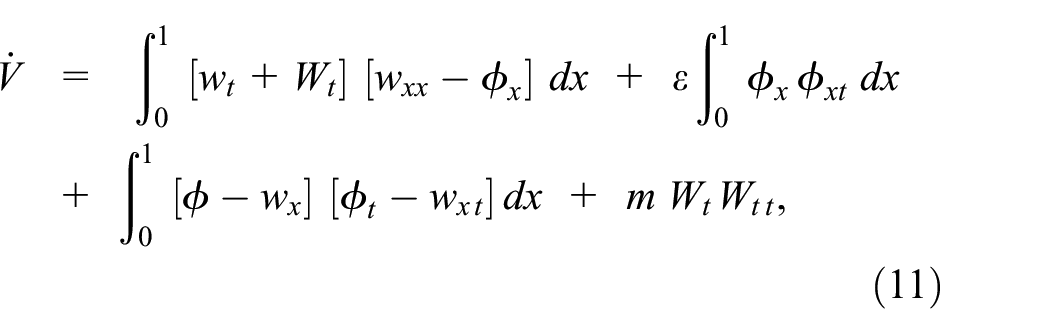
Multiplying the terms in the integrands of the first and the third integrals to obtain

Performing the integration of (12) and because of the boundary conditions (4)−(7) and (2), then (12) reduces to

Substituting (3) into (13), yields
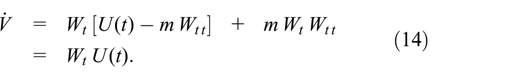
Substituting controller

For proving the passivity of the beam with the controller, we let


so, the system is passive, where
Proof: see Appendix A.
So, the shear beam model (1)−(2) with the feedback controller (8) is output strictly passive, and the feedback system is
Since the beam’s right end is fixed to the sliding base at

From the state feedback control principle,
26
the system can be stabilized by the input

where
Substituting the control component (20) into (19), yielding,

The feedback controller (21) takes the form of a classical proportional-derivative (PD) controller. The beam displacement,
Numerical calculation
In this section, numerical simulations will be used to verify the effectiveness of the passivity-based boundary controller and carried out using the finite-difference method.
The shear beam model can also be expressed in the following PDEs.


The derivation of the PDE (22) is shown in Appendix B, and (23) is from the boundary condition (4). Since the highest-order term of the PDEs is second-order, and there is only one integral term, it is easy to implement numerically.
The partial and ordinary differential equations of the system and controller developed in the previous section will be solved numerically. The finite difference method, a numerical solution technique, gives the discrete numerical values at a specific location called a grid point. Figure 2 shows the calculation grid, where

Calculation grid for the numerical scheme.
The first-order forward/backward difference equations and the second-order centered difference equation will be used in the calculations. The trapezoidal rule is used to solved the integration term.
By the finite difference method, the beam model (22) can be expressed as follows,
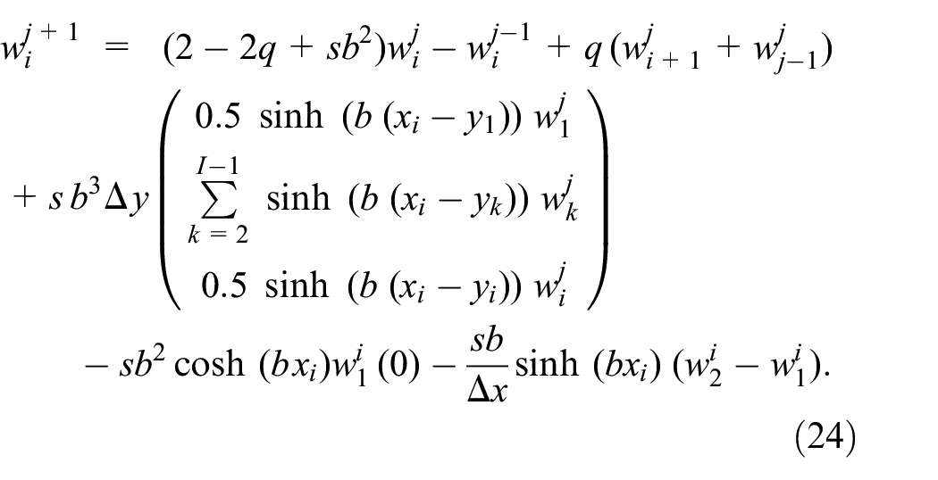
where
The first two rows in the calculation grid can be calculated from the initial conditions provided. After that, the elements
Results and discussion
In this section, the computer simulation results are presented. The PDE/ODE of the beam system and the controller are solved using the finite difference equations developed in the last section.
The numerical calculations are performed using MATLAB programming with the following parameters
The beam model is excited by the following initial conditions (Figure 3),7–9


The initial displacement and velocity at
The equations (25) and (26) are the initial displacement and the initial velocity at
Firstly, the sliding base was fixed for the beam without control, and then the beam was excited with the initial conditions. In this case, there was no damping term to dissipate the vibrating energy. Instead, there is only energy conversion back and forth between the kinetic and the potential energy. Therefore, the beam response was oscillatory, as shown in Figure 4, and the tip displacement is shown in Figure 5.

Beam simulation without control.

Tip displacement at
For the controlled case, the controller (21) is applied at the beam’s right end. The control action was performed via the sliding base movements. The beam response is shown in Figure 6. The beam with the passivity-based controller shows stability with

Beam simulation with control.
Figure 7, the tip displacements at

Tip displacements of the uncontrolled and controlled cases.
Figure 8 shows the tip displacement of the free end of the beam and the control action at the sliding base. The

Tip displacement at
In this paper,

The settling time
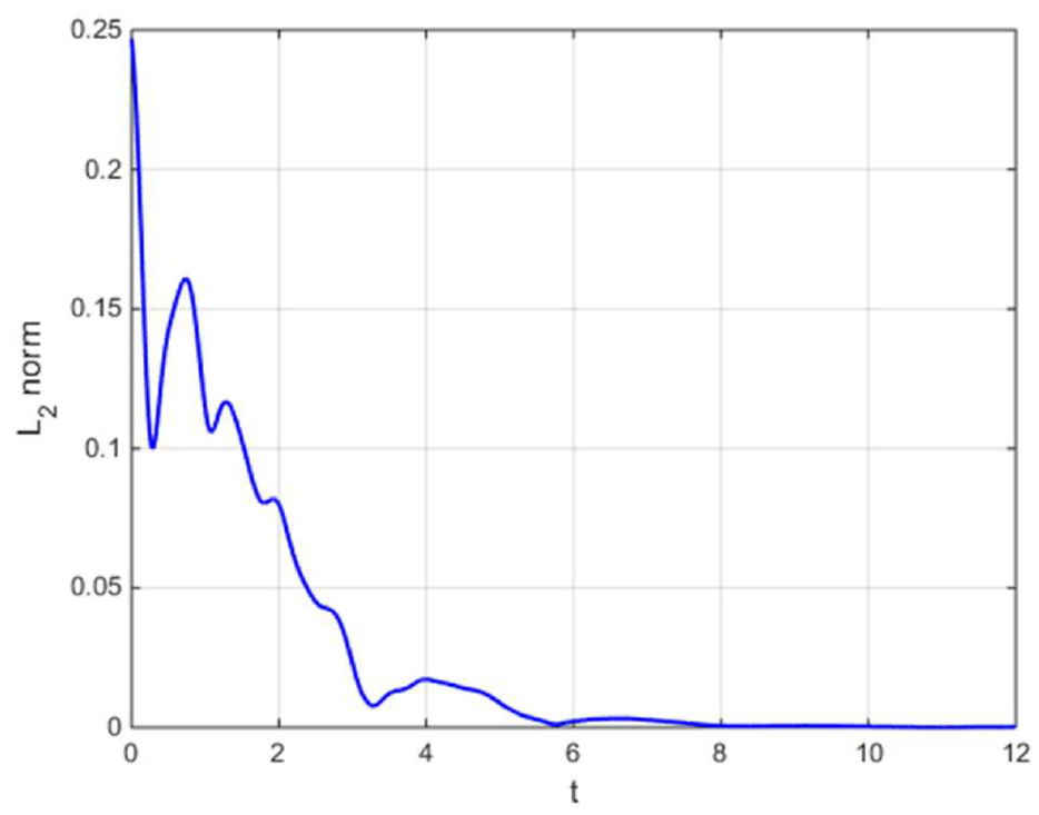
Figure 10 shows the snapshots of the beam displacement,

The beam displacement,
Effects of system and control parameter changes
In this section, the effects of the system and control parameter changes on the performance of the control scheme will be studied. The parameters that will be investigated are the system parameter
Firstly, the control parameters

The tip displacement with varying system parameters,
Figure 12 shows the settling times,

The settling times with the varying system parameters.
Secondly, both the system parameter,
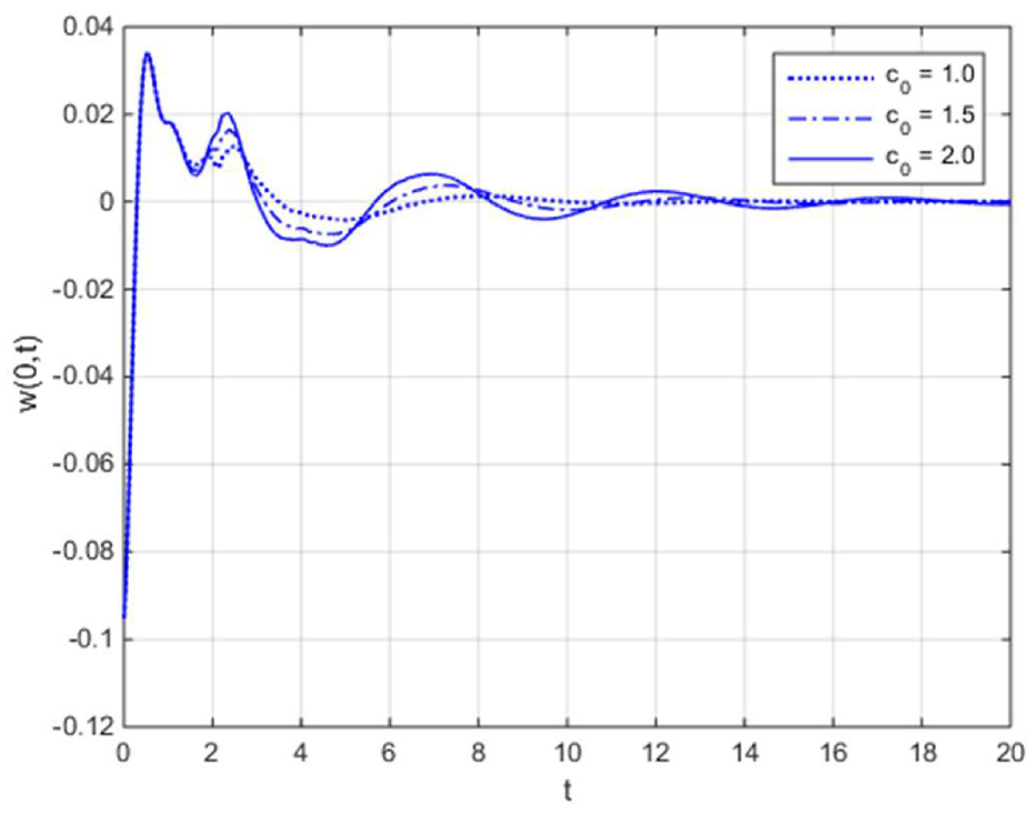
The tip displacement with varying elastic parameters.
Figure 14 shows the settling times of the varying values of the elastic parameters,

The settling times with the varying elastic parameters.
Finally, the damping parameters,

The tip displacement with varying damping parameters.
Figure 16 shows the settling times of the varying values of the damping parameter,

The settling times with varying damping parameters.
In summary, the system parameter,
Conclusion
The passivity-based boundary control for the vibration suppression of the undamped shear beam was investigated. This technique employed the energy principle in the controller design. The beam PDEs were treated directly without model reduction, so the control spillover problem was avoidable. The controller was designed by using the passivity property of the beam. The storage function, or the energy function, which consisted of the potential and kinetic energies, was defined and used to determine the passivity-based controller. The finite-gain
Footnotes
Appendix A
Appendix B
Handling Editor: Chenhui Liang
Declaration of conflicting interests
The author(s) declared no potential conflicts of interest with respect to the research, authorship, and/or publication of this article.
Funding
The author(s) received no financial support for the research, authorship, and/or publication of this article.