
Abstract
To address the vibration problem caused by gear clearance in the wind drivetrain, a two-degree-of-freedom internal model control (2-DOF-IMC) method was proposed to suppress the clearance’s nonlinear vibration. The two-mass wind drivetrain with clearance is the object of this paper’s research. First, we discuss the nonlinear characteristics of gear clearance and the mechanism by which vibration occurs. The nonlinear clearance unit is then decomposed into a linear unit and a nonlinear bounded disturbance unit. A suppression disturbance method based on 2-DOF-IMC was proposed to address nonlinear bounded disturbances. The 2-DOF-IMC overcomes the shortcoming of the PID control and the common internal model control (1-DOF-IMC) by allowing for independent adjustment of the anti-disturbance performance, effectively suppressing the nonlinear disturbance caused by gear clearance. A 2-DOF-IMC scheme and an IMC controller are designed, and the method’s effectiveness is validated through simulation.
Keywords
Introduction
The wind drivetrain consists of a wind turbine, a gearbox, a generator, and a transmission shaft. The gearbox comprises three sets of gears, there is clearance in the gear system. Gear clearance has nonlinear characteristics; its presence results in phase delay between the input and output signals of the control system, resulting in drivetrain vibration. The vibration of the drivetrain is extremely destructive to the transmission mechanism. Severe vibration may even result in damage or fracture of the transmission shafting, affecting the wind power system’s safe operation. 1 Therefore, it is necessary to investigate the vibration of the wind drivetrain and its suppression.
The research on vibration of drivetrain began in the 1970s. The primary focus of the research was on the mechanical resonance of the drivetrain of a servo system. With the development of wind power system, research on vibration and its suppression of the wind drivetrain has received increased attention. In reference, 2 an electromagnetic torque transient fluctuation and coupling vibration between components were analyzed using a model of a doubly-fed wind turbine. In reference, 3 a generator torque control method was proposed to reduce the mechanical stress of the wind turbine transmission chain based on the widely used two-mass model. However, the vibration caused by gear clearance in the drivetrain is not mentioned in above these references. For research of gear clearance, in reference, 4 the limit cycle characteristics and mechanical vibration caused by the nonlinearity of clearance are studied using a descriptive function analysis method. In reference, 5 limit cycles of speed control drive systems with clearance nonlinearity were analyzed using the eigenvalue method of nonlinear describing function. Reference 6 established a steering gear model with regard to reducer clearance. It used the description function method to analyze the frequency characteristics of the steering gear’s limit cycle while keeping transmission clearance in mind. The analysis method of the above references are the description function method, it is based on the classical control theory to solve the clearance nonlinear control problems. These methods are not only complicated, but also require the creation of graphs for analysis. It is inconvenient and inaccurate. Moreover, mechanical vibration caused by the elasticity of the drivetrain is typically eliminated by using the PID control method.7,8 However, the methods of suppressing the elastic vibration are not suitable for suppressing the nonlinear vibration of gear clearance. In 2000, reference 9 proposed an equivalent decomposition method for the nonlinear unit N of clearance, which is a novel theory on the nonlinearity of clearance. According to this theory, the gear clearance of the wind drivetrain can be decomposed into a combination of a linear unit H and a nonlinear bounded disturbance d. The linear unit H is incorporated into the linear section of the drivetrain, while the nonlinear section of the clearance serves as the disturbance of the system. Aiming at the disturbance caused by the nonlinearity of gear clearance, the paper proposed a control method with anti-disturbance ability to eliminate the influence of the nonlinearity of gear clearance. The disturbance observer is a typical method of suppressing the disturbance, but it needs to obtain accurately observation and compensation of disturbance.10,11 To effectively suppress the disturbance, the common internal model control (1-DOF-IMC) method is used in the early stage to suppress the nonlinear vibration of the wind drivetrain with clearance, with favorable results obtained. However, using the 1-DOF-IMC method 12 makes it difficult to achieve both excellent tracking and anti-disturbance performance at the same time. This cannot generally meet the requirements of the high-performance systems. The 2-DOF-IMC can adjust the system’s tracking and anti-disturbance performance, respectively. Controlling the system’s anti-disturbance performance, in particular, is advantageous. However, there is a lack of research on how to apply this method to wind power systems.
To suppress the clearance’s nonlinear vibration, the two-mass wind drivetrain with clearance is examined in this paper. First, we discuss the nonlinear characteristics of gear clearance and the wind drivetrain’s vibration. Then, a method for suppressing nonlinear bounded disturbances based on 2-DOF-IMC is proposed. The independent adjustment capability of 2-DOF-IMC effectively inhibited the nonlinear factors affecting of gear clearance. The simulation results demonstrate the method’s effectiveness.
Mathematical model of the two mass wind drivetrain
The two mass wind drivetrain
The wind drivetrain13,14 is shown in Figure 1.

The structural diagram of the wind drivetrain.
The wind turbine is connected via a low-speed shaft to the gearbox’s planetary gear train on the far left. A high-speed shaft connects the gearbox’s second parallel gear train to the generator on the right. The gearbox comprises three components: a planetary gear train, a first parallel gear train, and a second parallel gear train.
Figure 2 is a schematic diagram of the motion relation of the equivalent gear. In the diagram, the driving gear drives the driven gear, which must pass through the delay of 2b clearance.
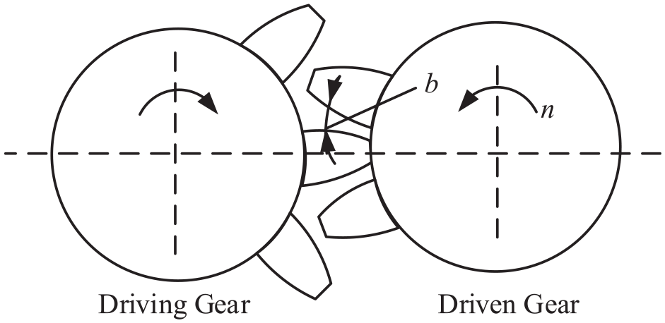
The schematic diagram of gear structure and motion relation.
To highlight the influence of clearance on the drivetrain and the application of a novel control strategy for suppressing drivetrain vibration with clearance, a typical two-mass model was selected as the research object for the wind drivetrain analysis. The reasons are as follows: (1) The multi-mass system containing M mass blocks is composed of M − 1 two-mass systems, 15 with the two-mass system serving as the basis. (2) The research conclusions of the two-mass system can be extended to the multi-mass system.
Because the wind turbine, gearbox, and generator are the three most fundamental components of the wind drivetrain, and the gearbox contains multiple gears and clearances. When using the two-mass model, it is necessary to carry out the necessary gearbox equivalence and conversion of the gearbox’s rotational inertia and elastic coefficient.
The driving gear’s elasticity is allocated to the low-speed shaft, and the moment of inertia is converted to the wind turbine. The driven gear’s elasticity is allocated to the high-speed shaft, and the rotational inertia is converted to the generator. To demonstrate the effect of gear clearance on the drivetrain, a clearance nonlinear module N is used to represent the equivalent total clearance of three gear systems in the gearbox. Finally, as illustrated in Figure 3, the mechanical structure of the two-mass drivetrain with gear clearance can be obtained.

The mechanical structure schematic diagram of a two-mass drivetrain.
In Figure 3,
Mathematical model of the two-mass wind drivetrain
When modeling the transfer function of a two-mass wind drivetrain with clearance, the gear clearance is not considered first. After obtaining the drivetrain’s transfer function structure diagram, the nonlinear clearance unit N is added. Because this paper primarily discusses drivetrain vibration, for the sake of simplicity, the gearbox transmission ratio is assumed to be one, when modeling the two-mass drivetrain’s transfer function.
It can be obtained from Figure 3:
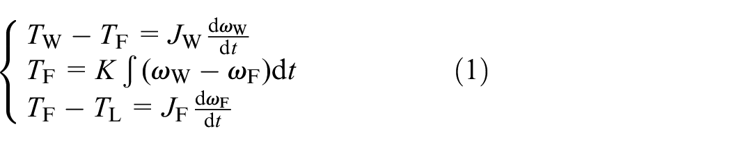
The Laplace transform of equation (1) is used to obtain equation (2):

The corresponding transfer function structure diagram can be obtained using equation (2). The nonlinear clearance module N is then added to the structure diagram, yielding the transfer function structure diagram of the two-mass wind drivetrain with gear clearance shown in Figure 4.

The transfer function structure diagram of the two-mass wind drivetrain with a clearance.
Vibration caused by gear clearance in wind drivetrain
Nonlinear characteristics of gear clearance and its influence
The gear clearance in the wind drivetrain is a nonlinear characteristic. 16 In the characteristics shown in Figure 5(a), the input is the position v of the driving gear, the output is the position q of the driven gear, 2b is the total clearance in the drivetrain, and the characteristic slope is k.

The nonlinear characteristics and influence on output signals with gear clearance: (a) the nonlinear characteristics with gear clearance and (b) the influence on output signals with gear clearance.
The input and output relation of gear clearance can be obtained from Figure 5(a), as shown in equation (3).

There are two main influences of gear clearance on control system:
Decrease in output signal amplitude and occur phase lag. As shown in Figure 5(b), the output signal is limited due to the influence of qm in gear clearance characteristics. Due to the influence of the clearance 2b, the output signal lags behind the input signal in phase by an angle of φ. Thus, the stability and dynamic performance of the system are affected, and the system’s instability is increased.
When nonlinearity gear clearance exists, the two-mass drivetrain changes from the linear system to the nonlinear system in Figure 4, and vibration may occur.
Experimental verification of nonlinear vibration of gear clearance
The system output of the same parameters without clearance was subtracted from the output of the two-mass wind drivetrain transfer function based on Figure 4. Thus, an experimental system capable of verifying clearance vibration is created, as shown in Figure 6(a). Speed deviation

Experimental verification of the clearance vibration and vibration waveform: (a) experimental verification scheme of the clearance vibration and (b) speed deviation waveform caused by clearance.
Methods to suppress wind drivetrain vibration with gear clearance
Mechanical vibration caused by the elasticity of the drivetrain is typically eliminated using the PID speed controller method. The PID speed controller can adjust the pitch angle of the wind turbine blades in order to adjust the driving torque applied to the blades and thus control the wind turbine driving torque TW. However, the wind turbine’s PID control method cannot suppress the vibration resulting from gear clearance,
Equivalence of nonlinearity with gear clearance
In Figure 5, the role of nonlinear gear clearance N in the system can be represented by the equivalent unit in the dotted box in Figure 7, where N is decomposed into two parts, N = H + d. 9 H(s) is a linear time-invariant system, and d(s) is a nonlinear time-varying system, representing a bounded disturbance. When the nonlinearity of the gear clearance is expressed as the bounded disturbance d(s), the control theory method can be used to eliminate the influence of the nonlinear disturbance of the gear clearance so that N presents a linear performance.

The nonlinear model of gear clearance.
The equivalence clearance characteristics N of the wind drivetrain is shown in Figure 8.

Equivalence of clearance characteristics.
Clearly, the graph of N lies between or on two parallel lines G+(v) = kv + b and G−(v) = kv − b for all v. Thus, N can be decomposed into N = H + d, where the transfer function of the linear part is H(s) = k, that is, the straight line passing through the origin of coordinates in the figure. d(s) is a nonlinear disturbance function bounded by b, in this case, 2b = 0.2. For the convenience of transformation, the slope k of the clearance characteristic is set to one. Then, the nonlinear unit N can be represented by H(s) = 1, and the nonlinear bounded disturbance function d(s) can be represented in the dotted box in Figure 7. That is, the nonlinear factor of clearance can be thought as the disturbance of the system.
When the nonlinear factor of gear clearance equals the bounded disturbance, a control strategy with a disturbance suppression function can be used to eliminate drivetrain vibration caused by gear clearance. This paper proposes a 2-DOF-IMC method. IMC is a type of control strategy that exhibits high anti-disturbance performance. The system’s anti-disturbance performance can be independently adjusted using 2-DOF-IMC.
Principle of IMC to suppress nonlinear disturbance of gear clearance
The general feedback system structure is shown in Figure 9. C(s) is the feedback controller, G(s) is the controlled object, and R(s) and Y(s) are the input and output signals of the control system, respectively. d(s) is an unmeasurable disturbance that corresponds to the bounded disturbance of the gear clearance’s nonlinear unit, when used to suppress the nonlinear vibration of the wind drivetrain with clearance.

Structural diagram of feedback control system.
As illustrated in Figure 9, because the feedback signal is derived directly from the system’s output, the effect of d(s) on the system’s output cannot be distinguished from that of other feedback factors, and the disturbance cannot be effectively controlled. If Figure 9 is transformed equivalently, the IMC structure depicted in Figure 10 can be obtained. So the disturbance d(s) is separated and used for feedback control.

The structure diagram of 1-DOF-IMC.
In Figure 10,
The suppression effect of IMC on disturbance can be analyzed 17 :
(1) IMC can adjust the output deviation caused by unmeasured disturbance d(s).
When the disturbance d(s) occurs, the system can suppress the unmeasured disturbance d(s) using the feedback adjustment mechanism. For example:

(2) When the model is matched with the controlled object, that is

If the model is matched with the controlled object,
The two-degree-of-freedom internal model control (2-DOF-IMC) principle
While the 1-DOF-IMC method effectively suppresses the influence of disturbances, it is challenging to achieve both excellent tracking and anti-disturbance performance in the same system. 2-DOF-IMC enables the system’s tracking and anti-disturbance performance to be adjusted independently.18,19 The structure of 2-DOF-IMC is depicted in Figure 11.
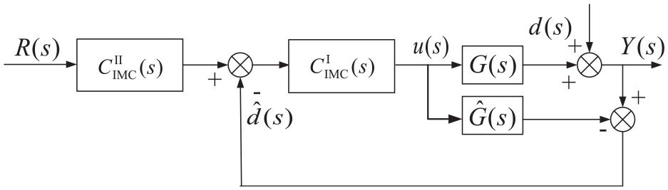
Block diagram of 2-DOF-IMC.
In Figure 11,

If the model is matched with the controlled object, that is
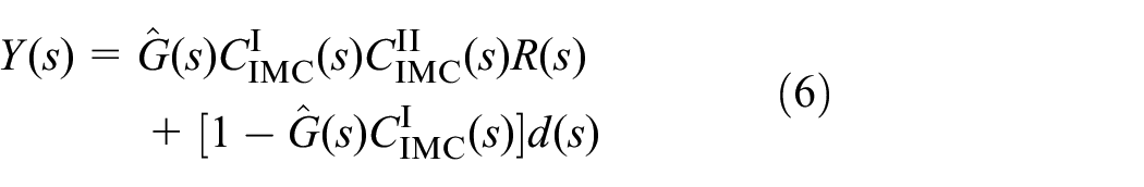

Since the controlled object contains no right half plane zero,

As shown in equation (8), the system’s tracking and anti-disturbance performance can be adjusted independently by adjusting the parameters of
Design of 2-DOF-IMC controller of the drivetrain
The design method of 2-DOF-IMC controller
(1)
where
(2) To allow for independent adjustment of the tracking and anti-disturbance performance of the system,

Where
In the formula,
The wind drivetrain’s control includes the control of the generator and wind turbine. The design process is as follows.
Design of 2-DOF-IMC controller for generator side
To design the generator side IMC controller, the controlled object G2(s) = ωF/TW (ratio of the generator speed to wind turbine torque) and the clearance nonlinear disturbance d(s) in Figure 4 must be transformed into the form in the dot-crossed box in Figure 10.
Structural diagram transformation of two-mass wind drivetrain for generator side
T L = 0 was substituted into Figure 4, and the clearance nonlinearity in Figure 4 was replaced by the equivalent unit in Figure 7. As a result, we get Figure 12(a). H(s) = 1 was substituted into Figure 12(a), and after a series of equivalent transformations, Figure 12(b) was finally obtained.
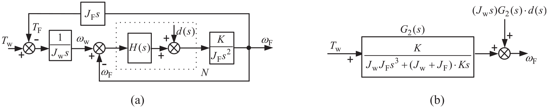
Equivalent transformation of structure diagram of the two-mass drivetrain of the generation side: (a) equivalent transformation of structure diagram (1) and (b) equivalent transformation of structure diagram (2).
In Figure 12(b):

The design of 2-DOF-IMC controller for generator side
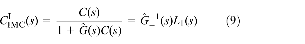
IMC controller CIIMC-F(s) design
From the expression of G2(s), it can be seen that G2(s) is a minimum phase system without zero in the right half-plane. Then, the controlled object G2(s) can be decomposed into
The experiment parameters.
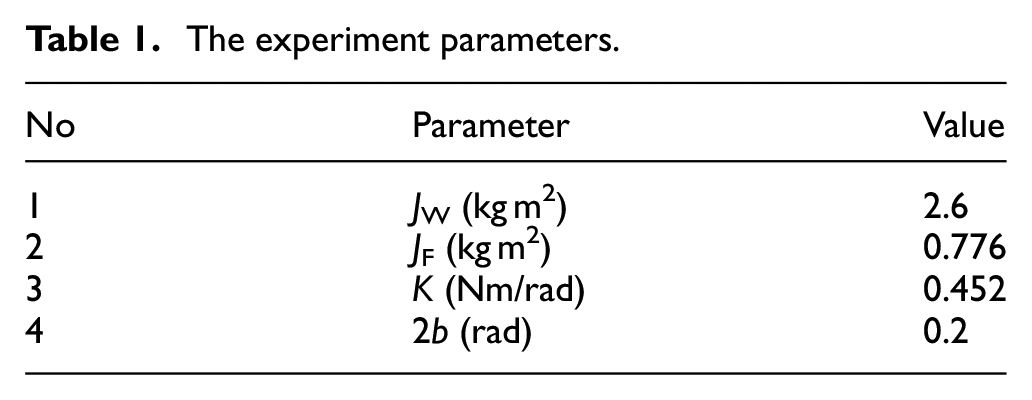
Substitute the parameters in Table 1 into G2(s), then:

In order to make the order of the numerator and denominator of the transfer function of the controlled object close, the low-pass filter can be selected as:

The designed IMC controller

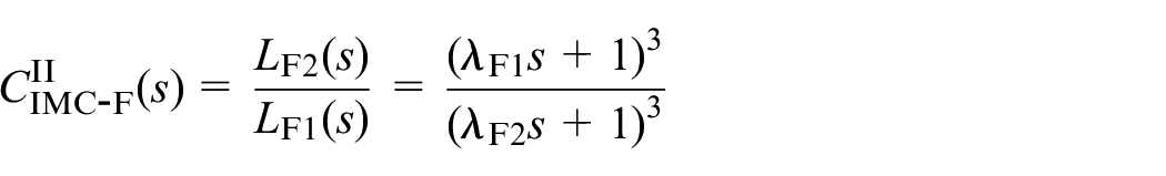
IMC controller CIIIMC-F(S) design
Choose

L F1(s) and LF2(s) are the filter of the generator side, λF1 and λF2 are the filter time constant.
Design of 2-DOF-IMC controller for wind turbine side
Structural diagram transformation of two mass drivetrain for wind turbine side
Figure 13 is the result of a series of equivalent transformations of the transfer function structure diagram, similar to the generator side.

Equivalent structure diagram of the two-mass drivetrain of wind turbine side.
The design of 2-DOF-IMC controller for wind turbine side
IMC controller CIIMC-W(S) design
In Figure 13,
Substitute the parameters in Table 1 into G1(s), we obtain the controlled object on the wind turbine side:
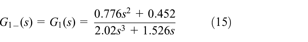
A low pass filter
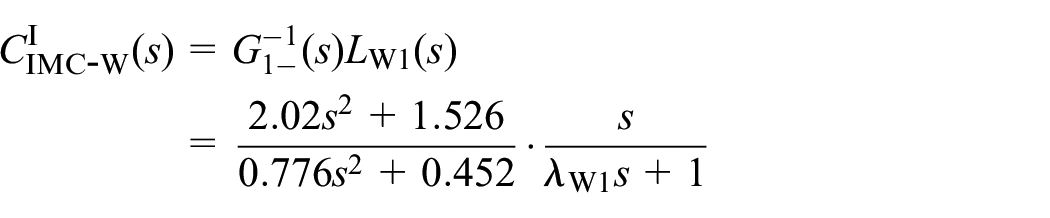
The designed wind turbine side IMC controller is as follows:

IMC controller
design
Choose

L W1(s) and LW2(s) are the filter of the wind turbine side, λW1 and λW2 are the filter time constant.
Simulation experiment and result analysis
The tracking and anti-interference performance of the wind turbine side
The tracking performance of the wind turbine side based on
(1) System simulation model of wind turbine side
2-DOF-IMC simulation model of the wind turbine side is established according to the structure in Figure 11.
(2) Model of the controlled object
The mathematical model of the controlled object can be expressed as:

(3) Wind turbine side IMC controllers are as follows:

(4) Simulation waveform and conclusions
The given input is set to 40*1(t), load disturbance input is 10*1(t − 13.5), 2-DOF-IMC is adopted, and three parameters (a), (b), and (c) in Table 2 are selected to obtain the tracking performance and anti-interference performance waveforms of the wind turbine output speed, as shown in Figure 14(a) to (c).
Selection schemes and conclusions for the three parameters in Figure 14.


The output speed curve of the system: (a) scheme (a), (b) scheme (b), and (c) scheme (c).
The anti-interference performance curve is shown in Figure 14. When parameters
The anti-interference performance of the wind turbine side based on CIIMC-W(S)
The given input is set to 40*1(t), load disturbance input is 10*1(t − 15). Three parameter selection schemes (a), (b), and (c) in Table 3 are taken. The wind turbine side’s tracking performance and anti-interference waveforms corresponding to schemes (a), (b), and (c) are shown in Figure 15(a) to (c).
Selection schemes and conclusions for the three parameters in Figure 15.


Output speed response curve of the system: (a) scheme (a), (b) scheme (b), and (c) scheme (c).
The anti-interference performance curve is shown in Figure 15. It can be concluded that the anti-interference performance of the wind turbine speed can be adjusted by modifying the parameter
The tracking and anti-interference performance of the generator side
The tracking performance of the generator side based on CIIIMC-F(S)
(1) System simulation model of generator side
2-DOF-IMC simulation model of the generator side is established according to the structure in Figure 11.
(2) Model of the controlled object
The mathematical model of the controlled object can be expressed as:

(3) Generator side IMC controllers are as follows:

(4) Simulation waveform and conclusions
The given input is set to 40*1(t), load disturbance input is 5*1(t − 12), 2-DOF-IMC is adopted, and three parameters (a), (b), and (c) in Table 4 are selected to obtain the tracking performance and anti-interference performance waveforms of the generator output speed, as shown in Figure 16(a) to (c).
Selection schemes and conclusions for the three parameters in Figure 16.


The output speed curve of the system: (a) scheme (a), (b) scheme (b), and (c) scheme(c).
The anti-interference performance curve is shown in Figure 16. When parameters
The anti-interference performance of the generator side based on
The given input is set to 40*1(t), load disturbance input is 5*1(t − 15), 2-DOF-IMC is adopted. Three parameter selection schemes (a), (b), and (c) in Table 5 are taken. The generator side’s tracking performance and anti-interference waveforms corresponding to schemes (a), (b), and (c) are shown in Figure 17(a) to (c).
Selection schemes and conclusions for the three parameters in Figure 17.
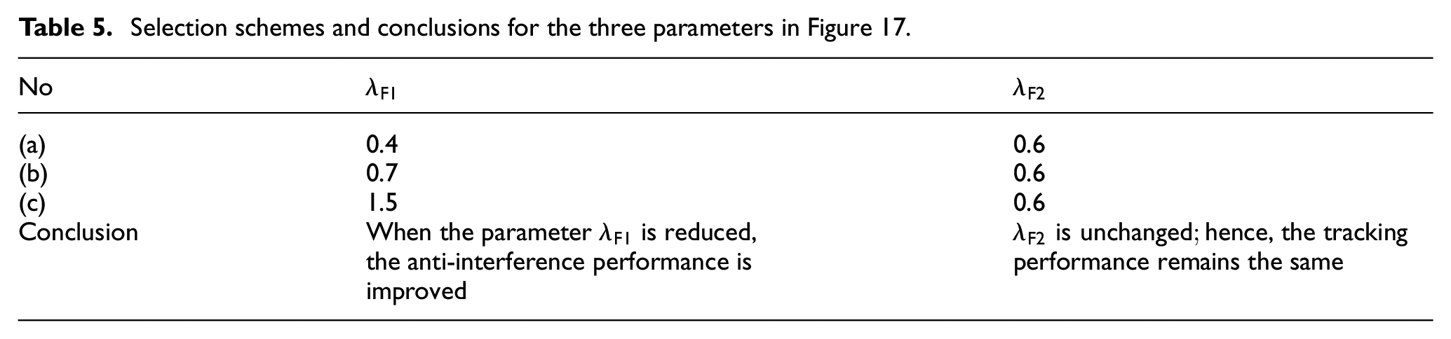

Output response curve of the system: (a) scheme (a), (b) scheme (b), and (c) scheme (c).
The anti-interference performance curve is shown in Figure 17. It can be concluded that the anti-interference performance of the generator speed can be adjusted by modifying the parameter
Speed of wind turbine and generator with clearance based on PID controller, compared with 2-DOF-IMC
Experimental scheme: The experimental scheme of wind turbine speed feedback PID control is shown in Figure 18, the drivetrain parameters are from Table 1, and PID parameters of speed controller are obtained based on reference. 21
Experimental results and analysis: The wind turbine’s speed waveform is shown in Figure 19(a).

The wind turbine speed feedback control system based on PID controller.

The speed waveform of the two-mass wind drivetrain with a clearance: (a) wind turbine speed waveform and (b) generator speed waveform.
The output speed of wind turbine and generator controlled by 2-DOF-IMC have no vibration at all, and the tracking performance and anti-disturbance performance can be adjusted flexibly, compared with the commonly used PID controller.
Speed of wind turbine based on 1-DOF-IMC, compared with 2-DOF-IMC
(1) Experimental scheme: The experimental scheme of the wind turbine based on 1-DOF-IMC is obtained according to Figures 10 and 13, the mathematical model of the controlled object can be expressed as:

1-DOF-IMC of the wind turbine side is as follows:

(2) Experimental results and analysis: The wind turbine’s speed waveform is shown in Figure 20. The solid and dashed lines in the figure are the tracking performance and anti-disturbance performance of the output speed of the wind turbine, when the parameter λ are 0.5, and 1.5, respectively. It can be seen that when the parameter λ is changed, the tracking performance and the anti-disturbance performance of the wind turbine’s speed change at the same time, which cannot be adjusted independently. However, the tracking performance and anti-disturbance performance controlled by 2-DOF-IMC can be adjusted flexibly.

The wind turbine’s speed waveform based on 1-DOF-IMC.
Conclusion
This paper analyses the nonlinear vibration by taking the two-mass wind drivetrain with clearance as the research object. Since the clearance nonlinear unit N can be decomposed equivalently into a linear unit and a nonlinear bounded disturbance unit, the following work is performed in this paper, and the following conclusions are drawn.
A disturbance suppression method based on the IMC principle was used to address the nonlinear bounded disturbance caused by the gear clearance. By utilizing IMC’s effective anti-disturbance function, the nonlinear disturbance caused by gear clearance is suppressed. A 2-DOF-IMC speed controller is designed for a wind turbine and generator side in a two-mass drivetrain. It is demonstrated that the tracking and anti-disturbance performance of the system can be adjusted independently, and anti-disturbance performance changed by adjusting the filter parameters of the IMC controller
Footnotes
Handling Editor: Chenhui Liang
Declaration of conflicting interests
The author(s) declared no potential conflicts of interest with respect to the research, authorship, and/or publication of this article.
Funding
The author(s) disclosed receipt of the following financial support for the research, authorship, and/or publication of this article: This work was supported in part by the National Key Research and Development Program of China, No. 2020YFB1711102.
Data availability statement
The data that support the findings of this study are available from the corresponding author upon reasonable request.