
Abstract
In order to improve the cutting performance of toroidal worm gear hob and the tooth surface accuracy of hobbing worm gear, to control the absolute value of the side rake angle of each cutter tooth to be smaller and more balanced on the left and right sides, a method of developing the rake face of toroidal worm gear hob with spiral groove by using conical production surface is proposed. According to the theory of gear meshing rationality, the mathematical model of the rake face is established. The analysis and calculation example results show that the absolute value of the rake angle on both sides changes with the transmission ratio coefficient. By studying this change law, the optimal milling transmission ratio coefficient k = 0.886 is obtained. Meanwhile, the corresponding absolute value of the rake angle is between ±4.5°, which reduce the absolute value of the rake angles on both sides of the cutter teeth effectively and make the rake angles on the left and right sides be more balanced. The spiral groove was simulated, and the rake angle was measured in the simulation software. The measured results are consistent with the calculated results, which prove the correctness of this method.
Introduction
Toroidal worm drive is an excellent transmission form widely used in the field of mechanical transmission; especially the plane secondary enveloping toroidal worm drive, it has independent intellectual property rights in my country and is unique in the field of mechanical transmission. However, its special structure makes the design and processing of the toroidal worm pair more complicated, especially the processing and manufacture of the toroidal worm gear hob is more difficult.1,2 Because the rake angle range of the toroidal worm gear hob is difficult to control accurately, the cutting performance of the worm gear hob and the tooth surface quality of the hobbing worm gear are seriously affected in actual production. 3 The type of chip holding groove of hob affects the shape of the edge line of hob tooth, determines the rake angle on both sides of hob tooth, and then affects the quality of hobbing worm gear. The straight groove hob causes a positive and a negative rake angle on both sides of the cutter teeth. The larger negative rake angle leads to poor cutting conditions or even be unable to process the cutter teeth, reducing the tooth surface accuracy of the worm gear. Larger positive rake angle is easy to cause serious wear of cutter teeth and reduce the service life of hob. 4 Therefore, the chip holding groove of the toroidal worm gear hob is usually designed as a spiral groove to ensure that the absolute value of the rake angle on both sides of the cutter tooth is small and the rake angle on both sides is relatively balanced.
When machining the toroidal worm, a general mathematical model of hobbing gear with NC Hobbing Machine is established, and concluded that the geometric error of hob is one of the important factors affecting gear accuracy. 5 In order to improve the machining accuracy, the gear error caused by the grinding of hob is introduced. 6 In terms of the cutting performance of the hob, different methods for machining more accurate worm gear surfaces are proposed.7–10 And the worm gear tooth surface deviation caused by the cutting error of hob is studied. 11
For the different types of grooves, the straight chip groove toroidal worm gear hob is studied, and the mathematical model of the rake face of the straight groove hob is established.12,13 It is suitable for machining the worm gear in the single head toroidal worm drive. When the number of hob heads is large, this straight groove hob will have a great adverse impact on the hobbing of the worm gear, and the spiral chip holding groove needs to be adopted.14,15 In order to studied the cutting error between the actual machining face and the theoretical rake face caused by the motion of milling cutter, the mathematical model of machining the rake face of helical groove of cylindrical hob with disk milling cutter is established. 5 By analyzing the orthogonal curve of the tooth pattern helix of the circular arc worm, the transmission ratio formula for forming the orthogonal curve of the worm helix is derived. 16 However, he did not provide the machine tool motion parameters when machining the guide groove of the circular arc worm hob into the helical groove, nor did he obtain the mathematical expression of the orthogonal curve. By analyzing the deficiencies of straight groove hob, the grinding of spiral chip holding groove of gear hob is studied. 17 Due to the variety of the cutting edge curve on both sides of each cutter tooth and the spiral angle of each point on the spiral surface of the hob, the spiral chip holding groove of the toroidal worm gear hob cannot be determined as simply as the gear hob, and it is not easy to ensure the balance of the front angles on the left and right sides of the cutter tooth.18,19
In this paper, a method of generating the spiral groove of toroidal worm gear hob from conical generating surface is proposed, and the conjugate condition equation of generating the rake face of spiral groove from conical generating surface is obtained. Therefore, the mathematical model of the rake surface of spiral groove of planar double enveloping toroidal worm gear hob is established. The optimal milling transmission ratio is obtained by optimizing the variation law of rake angle, and then a more ideal rake face is obtained; The spiral chip holding groove is simulated by VERICUT software. The rake angles on both sides of the cutter teeth are measured in the simulation software and compared with the theoretical values to verify the correctness of the design method and mathematical model.
Mathematical model of rake face
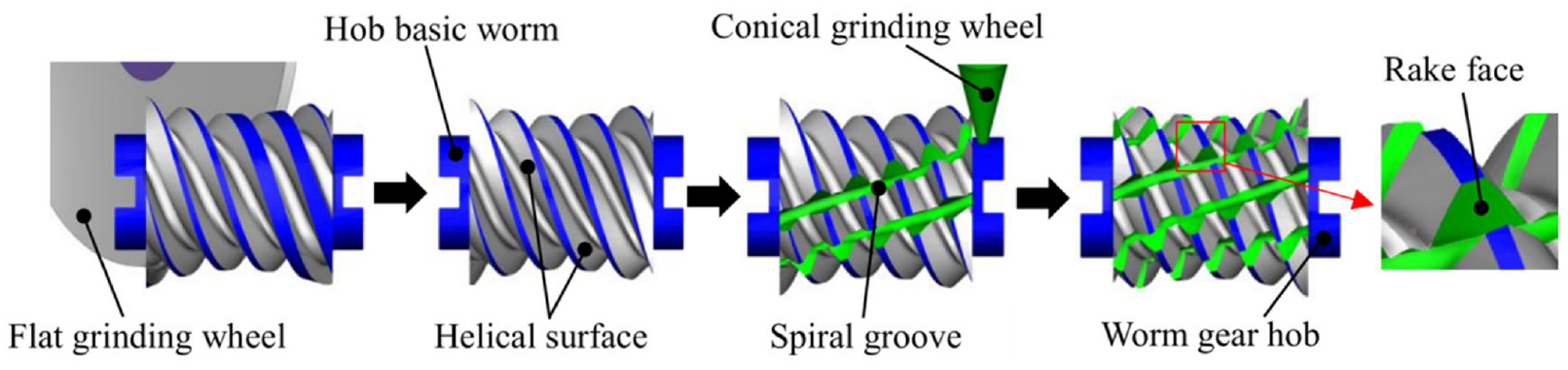
Take a plane as the production surface Σd. The primary envelope develops into a helix Σ1 toroidal worm, which is called plane enveloping toroidal worm; by using Σ1 as the production surface of hob, the secondary envelope is developed into the tooth surface of worm gear Σ2. The above toroidal worm and worm gear are matched to form a plane double enveloping toroidal worm pair. Among them, toroidal worm with Σ1 as the production surface of hob is called hob basic worm.
Mathematical model of basic worm helical surface of hob
The forming principle of the helical surface of the plane enveloping hourglass worm is shown in Figure 1. When grinding the helical surface, production surface Σd is tangent to the main base circle of worm gear with radius rb; the production surface Σd is at an angle of β with the rotary axis of the cutter base, φd is the corner of the cutter base. The u and v are parameters of the flat production surface Σd.

Envelope generating hob basic worm helical surface Σ1 from plan Σd.
According to the gear meshing principle, the mathematical equation of the basic worm helical surface of hob is as follows:

In the formula: Φ1 = (v)d1(n1)1 is the conjugate conditional equation. At the processing point, (vd1)1 is the expression for the relative velocity of a point on the production plane Σd and a point on the basic worm helical surface of hob Σ1. At the processing point, (n1)1 is the expression for unit normal vector on hob basic worm helical surface Σ1. (r1)1 represents the worm helical surface Σ1. The coordinate component is {x1, y1, z1}.
Relationship between coordinate system and relative motion of machining rake face
As shown in Figure 2, take the conical surface as the production surface Σqd, envelop the basic worm of the hob out of the spiral groove to form the rake face of the spiral groove Σ3. The forming method of spiral groove rake face Σ3 determines the shape of the edge line, and then determines the size of the rake angles on both sides of the cutter teeth and the efficiency and accuracy of the hob in cutting the worm gear.

Conical production surface and spiral groove hob.
As shown in Figure 3, the static coordinate system of the hob basic worm is σqo1 (Oqo1; iqo1, jqo1, kqo1). The dynamic coordinate system is σq1 (Oq1;
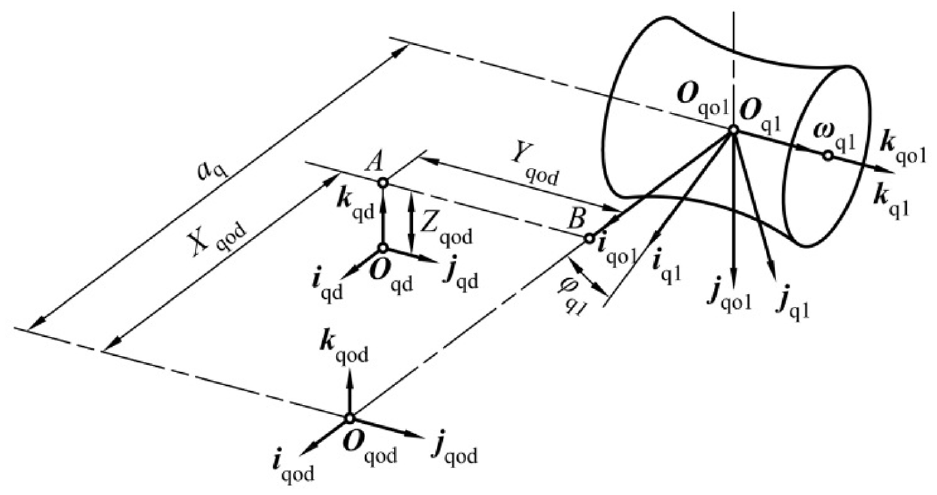
Position and selected coordinate system of basic worm and cutter base of hob.
As shown in Figure 4, the following are the main points when designing the chip holding groove of the hob. The front end face of the conical production surface coincides with the origin Oqd of the static coordinate system of the cutter base. And the center of the front end face of the milling cutter has its coordinates in the σqod coordinate system, which are (Xqod, Yqod, Zqod). The milling cutter rotation axis coincides with the coordinate axis iqd. The conical production surface moves along the iqd axis and jqd axis at a certain speed in the σqd coordinate system, and the change of the displacement of the milling cutter along the jqd axis is ΔZ. At the same time, the hob basic worm rotates around the c-axis at a certain angular velocity ωq1 in σq1 coordinate system, and the change of its angle is Δφq1. The chip holding groove of the hob at the bottom of the arc groove is processed with a certain milling transmission ratio icz to form the rake face of the hob. And its milling transmission ratio is icz = Δφ1/ΔZ = |ωq1|/|vz|. When ωq1 = 0, which means the milling transmission ratio is zero, the straight chip groove hob is processed. When ωq1 ≠ 0, which means the milling transmission ratio is not zero, the spiral chip holding groove hob is processed.

Spiral chip holding groove developed from conical production surface.
Expression of fixed transmission ratio
As shown in Figure 5, it is a row of cutter teeth of toroidal worm gear hob. And l is the helix of indexing circle on the left helix. At any point on l, the lead angle of l is γ. And at each radial section Zi = 0 of the hob basic worm, the lead angle on the helix of the indexing circle is equal. The rake face of toroidal worm gear hob is also a helical face, l′ is the helix of indexing circle on the rake face, and the lead angle at each point on l′ is η. According to the calculation formula19,22 of helix lead angle:


Helix of indexing circle.
In the formula, vd is the linear speed at where the tool rotates around the turntable when machining the basic worm surface of the hob. v1 is the linear speed at where the worm blank rotates, vz is the speed at which the tool moves when machining the rake face, and vq1 is the linear speed at which the basic worm of the hob rotates. (Note: The helical surface of the hob basic worm discussed in this paper is right-handed, so the lead angle γ of its helix is positive. And the rake face of hob is left-handed, so the lead angle η of its helix is negative.)
For the multi head (z1 ≥ 3) toroidal worm gear hob, using the fixed transmission ratio to process the rake face can only ensure that the edge characteristics of the throat cutter teeth meet the design requirements. While the edge characteristics of other cutter teeth are different, especially the difference between the edge characteristics of the two edge teeth and the throat cutter teeth is large. It is necessary to use the variable transmission ratio to process the rake face, so that the edge characteristics of each row of cutter teeth can meet the design requirements.
As shown in Figure 6, it is the throat tooth of the toroidal worm gear hob. M is the throat point on the left helical surface and it is on the helix of indexing circle. And the lead angle of M on the helix of the helical surface is γm. The rake face of toroidal worm gear hob is also a helical face. There must be a helix on the rake face passing through point M. It is assumed that the lead angle of point m on the helix of the rake face is ηm.

Throat teeth of toroidal worm gear hob.
In order to make the included angle of two helices at point M meet different design requirements, γm and ηm shall satisfy the following relation23,24:

In the formula, k (k > 0) is an orthogonal coefficient. When k = 1, which means γm + |ηm| = π/2, the two helices are orthogonal at point M. At this time, the included angle of the two curves at point m is 90°. When k > 1, which means γm + |ηm| > π/2, the included angle of the two curves at point M becomes larger; When 0 < k < 1, which means γm + |ηm| < π/2, the included angle of the two curves at point m becomes smaller.
Set v1 = 1/2ω1d1 and vd = 1/2ωdd2 into formula (2):

In the formula, d1 is the diameter at point M on the worm indexing circle surface, d2 is the indexing circle diameter of the worm gear.
Set id1 = |ωd|/|ω1| and d1 = 2a − d2 into formula (5):

Set vq1 = 1/2ωq1d1 into formula (3):

Set |ωq1|/|vz| into the formula of icz:

Set ηm = −(kπ/2 − γm) from formula (4) into the icz from formula (8):

The above formula is the expression of constant transmission ratio icz for machining the rake face of toroidal worm gear hob on general NC machine tool with C-axis. Among this, γm is a fixed value. And the orthogonal coefficient k can be given different values to change the cutting edge characteristics of throat cutter teeth at point M.
Equation and normal vector of conical surface Σqd
A conical milling cutter is used to mill the rake face in order to ensure the accuracy of the rake face. Figure 7 shows the conical production surface, and its parameters are ρ and θ.

Conical plane.
The equation of the shaped cone Σqd in the cutter base moving coordinate system σqd is:

The equation of the shaped cone Σqd in the coordinate system σqod is:

Among them:

The vector expression of the shaped cone Σqd in the moving coordinate system σq1 is:
Among them:

The coordinate expression is:

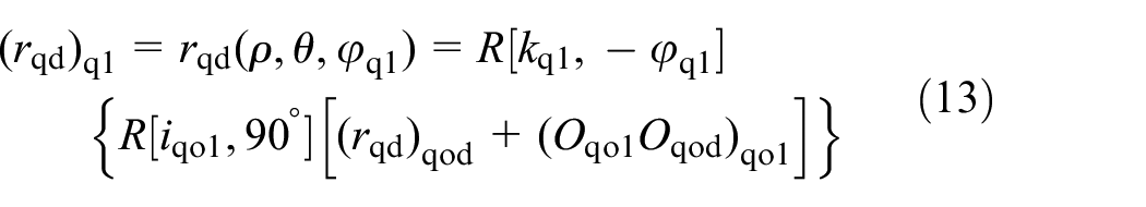
Therefore, the expression of any point on the rake face in the coordinate system σq1 is:

The unit normal vector of any point on the conical production surface Σqd in the coordinate system σqd is:

For the entity whose normal vector nqd direction is from the airspace to the grinding wheel. And it is from its entity to the airspace for the worm. In this way, the normal vectors on the grinding wheel and worm are the same at the same point. Therefore, the reverse direction is taken to make the normal vector point to the entity from the airspace in this example, and the unit normal vector of any point on the conical production surface Σqd is the same in the coordinate system σqod and σqd. Therefore, the expression of the unit normal vector of any point on the rake face in the coordinate system σqod is:

Conjugate conditional equation
In the coordinate system σqod, the relative velocity between the conical generating surface and the rake face is (Vqd1)qod at the machining point M. The first envelope conjugate condition equation is obtained from the gear meshing principle25,26:

Among them:


The rotational speed of the hob basic worm in the coordinate system σq1 is (ωq1)q1, and its expression is:

The rotational speed of the hob basic worm in the coordinate system σqo1 is (ωq1)qo1, and its expression is:

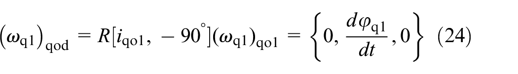
The rotational speed of the hob basic worm in the coordinate system σqod is (ωq1)qod, and its expression is:
The relative rotational speed of hob basic worm and milling cutter in the coordinate system σqod is (ωqd1)qod, and its expression is:

The milling cutter does not rotate, so the rotation speed of the milling cutter (ωqd)qod = 0.
Set formula (24) and (ωqd)qod = 0 into formula (25):

The relative linear velocity between the hob basic worm and milling cutter in the coordinate system σqod is (vqd1)qod, and its expression is:

The linear velocity of the milling cutter in the coordinate system σqod is (vqd)qod, and its expression is:

The hob basic worm does not translate, so the moving speed of the hob basic worm: (vq1)qod = 0.
Set formula (28) and (vq1)qod = 0 into(27):

Set formulas (26), (11), (21), (31) and (27) into (20):

Set formulas (30) and (18) into (19):

Order
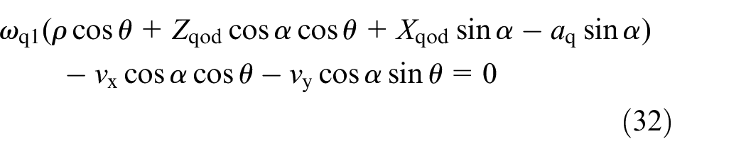
The first envelope conjugate condition function is obtained from

Mathematical model of rake face Σ3
The rake face Σ3 is represented by (rqd)q1 in the coordinate system σq1, and its coordinate components are {xq1, yq1, zq1}. According to the gear meshing principle, the mathematical equation of the rake face of the spiral groove is as follows:

Numerical example and result analysis
The cutting edge line of the hob tooth can be obtained by combining the equation (1) of helical surface Σ1 of hob basic worm with the equation (34) of the rake surface Σ3 of the helical groove. From the normal vector (nq1)1 of any point of the edge line of hob tooth on the rake face and the normal vector (n1)1 on the spiral face, the expression of the rake angle Vq at this point is as following 27 :

Among them: arccos[(nq1)1·(n1)1] is recorded as the included angle at that point Wq.
As shown in Figure 6, the edge line of hob tooth between the left helical surface and the rake surface of the hob basic worm is the left edge line, and the rake angle at any point of the left edge line is the left rake angle. Similarly, the rake angle at any point on the right edge line is the right rake angle. In this paper, according to the calculation example 28 provided in Table 1, the cone angle of the cone generating surface is used as constant value α = 8°. When k = 1, the rake angle of spiral chip holding groove hob from outlet to inlet on the indexing circle surface is shown in Table 2.
Parameters of a plane double enveloping toroidal worm gear hob.

Rake angles of each tooth on the index circle when k = 1.

The variation law of rake angle of hob for machining spiral chip holding groove is shown in the following figure:
It can be seen from Figure 8 that the front angles on the left and right sides of the spiral chip holding groove hob are between ±11.5°. The left side is the positive front angle and the right side is the negative front angle. From the outlet (no. 1 tooth) to the inlet (no. 5 tooth), the absolute value of the front angle first decreases and then increases. Because it is the transmission ratio calculated based on the lead angle of the throat position, the absolute value of the front angle of the throat tooth position (no. 3 tooth) is the smallest.

The variation laws of rake angles on the index circle when k = 1.
Optimization of transmission ratio
Determine the optimal milling transmission ratio coefficient
The cutting edges on the left and right sides of the cutter teeth are processed at the same time. While reducing the negative rake angle on the left side, the positive rake angle on the right side also decreases. It can be seen from Table 2 that when the milling transmission ratio coefficient k = 1 and the milling transmission ratio icz = −0.0121, the rake angles on the left and right sides of the spiral cutter are about ±11.5°. In order to reduce the absolute value of the rake angles on the left and right sides of each cutter tooth as much as possible, it is necessary to determine the optimal milling transmission ratio coefficient k to determine the optimal milling transmission ratio.
Taking the four head hob as an example, changing the milling transmission ratio coefficient k. The values of different milling transmission ratios and the rake angles on the left and right sides of the cutter teeth on the indexing circle are shown in Tables 3 and 4:
Comparison of the rake angles on the left side under different transmission ratios.

Comparison of the rake angles on the right side under different transmission ratios.

Under different milling transmission ratios, the variation law of the left rake angle on the indexing circle surface of the four head spiral groove hob is shown in Figure 9 (the radial section position Zi of the hob is not considered here for comparison, and only the rake angle corresponding to each cutter tooth is considered):

The laws of the rake angles on the left side of the hob under different milling transmission ratio.
The variation law of the right rake angle on the indexing circle surface of four head spiral groove hob under different milling transmission ratios is shown in Figure 10:

The laws of the rake angles on the right side of the hob under different milling transmission ratio.
It can be seen from Tables 3 and 4 that when k = 1 and icz = −0.0121, the absolute value of the left and right rake angles of the cutter teeth is between −9.8° and 11.5°.
When k > 1, which means the milling transmission ratio decreases, the absolute values of the negative rake angle and positive rake angle on the left and right sides of the cutter teeth increase between −11.7° and 12.6°. Therefore, it is not suitable to reduce the milling transmission ratio.
When 0 < k < 1, with the decrease of k value, the milling transmission ratio increases. So the absolute value of the rake angle on the left side of the cutter tooth gradually increases, and the absolute value of the rake angle on the right side gradually decreases.
It can be seen from Figure 9 that the negative rake angle on the left side of the cutter tooth is mainly caused by no. 3 tooth. With the increase of milling transmission ratio, the absolute value of the negative rake angle of no. 3 cutter tooth increases.
It can be seen from Figure 10 that the negative rake angle on the right side of the cutter tooth is mainly caused by no. 1 tooth. With the increase of milling transmission ratio, the absolute value of the negative rake angle of no. 1 cutter tooth decreases.
In order to make the maximum negative rake angle on the left and right sides of the cutter tooth equal, the optimal milling transmission ratio coefficient k is determined with the goal of the absolute value of the negative rake angle on the left side of no. 3 tooth and the negative rake angle on the right side of no. 1 tooth being equal. Under different milling transmission ratio coefficients, the rake angle changes on the left side of no. 3 cutter and the right side of no. 1 cutter are shown in Figure 11:

The laws of the rake angles for teeth no. 3 and no. 1.
It can be seen from the above figure that when the milling transmission ratio coefficient k = 0.886, the maximum negative rake angles on the left and right sides of the cutter teeth are equal. Both of them are −4.2°. At this time, the milling transmission ratio icz = −0.0191.
Variation law of front angle after optimization
As shown in Table 5, the optimized transmission ratio icz = −0.0191 is used to process the spiral chip holding groove of four head hob, and the rake angles on the left and right sides of the cutter teeth on the indexing circle are calculated:
Comparison of the rake angles on the indexing circle when icz = −0.0191.

When icz = −0.0191, the variation law of left and right rake angles on the indexing circle surface of four head hob is shown in Figure 12:

The laws of the rake angles on the index circle when icz = −0.0191.
It can be seen from Table 5 that the rake angle on the left side of the hob is between −4.2° and 3.6°, and the rake angle on the right side of the hob is between −4.2° and 4.5°. The rake angles on both sides of the cutter teeth are more balanced, which is conducive to cutting.
As shown in Figure 13, comparing the optimized rake angle in Table 3 with the optimized rake angle in Table 5, it can be seen that the absolute value of the maximum positive rake angle on the left side of the hob decreases from 11.5° to 4.2°, with a decrease of 63.5%. And the absolute value of the maximum negative rake angle on the right side of the hob decreases from 9.8° to 4.5°, with a decrease of 54.1%. The rake angles on both sides of the cutter teeth are more balanced, which is conducive to cutting.

The comparison of the initial value and the optimized value of the rake angle.
VERICUT machining hob spiral chip holding groove
Taking the 4-head hob in Table 1 as an example, a CNC machine tool29,30 with three-axis linkage of c-axis, x-axis, and z-axis is established in VERICUT software to simulate the processing of the basic worm helical surface of hob and the chip holding groove of hob spiral. The spiral surface and spiral chip holding groove of the hob basic worm processed by simulation are shown in Figure 14:
Simulation processing results.
Measure the included angle Wq on both sides of the cutter teeth on the indexing circle after the simulation machining of the spiral chip holding groove hob is completed, as shown in Figure 15.

Measuring included angle: (a) measurement software interface and (b) measuring angle dimension.
Calculate the rake angle V on both sides of the cutter teeth from V = Wq − 90°, as shown in Table 6.
Measuring the rake angles on the index circle by using the variable milling ratio.

Comparing the measurement results in Table 6 with the theoretical calculation results in Table 5, the error changes between the measured and theoretical values of the left and right front angles are shown in Figures 16 and 17.

Comparison of left front corner.
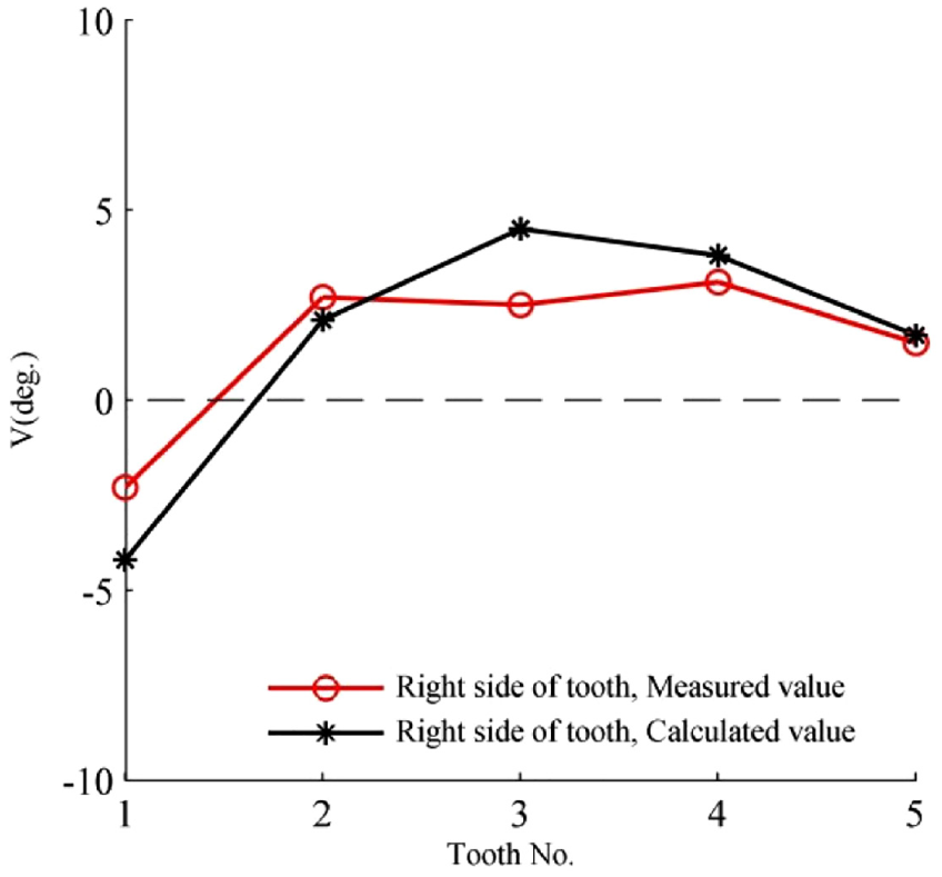
Comparison of right front corner.
As shown in Figure 16, the measured value of the left front angle first increases, then decreases and then increases. The measurement error value at the throat position is small. And the measurement error of no. 2 tooth is large, which is 1.9°. As shown in Figure 17, the measured value of the right front angle first increases, then decreases and then increases. The measurement error at the throat position (no. 3 tooth) is large, and the maximum measurement error is 2.0°. The change law of the measured value of the left and right front angles is basically consistent with the change law of the theoretical calculation value. The difference between the measured value and the theoretical calculation value are ±4.6°, reflecting the correctness of the theoretical calculation.
At the same time, there are errors in the measurement results. The maximum error occurs in the right front angle of no. 3 cutter tooth, which is 2.0°; the minimum error occurs at the left front angle of no. 3 cutter tooth, which is 0.1°. The measurement error is caused by the error of the selected position 31 of the measurement point, that is, there is a deviation when the point on the helix of the indexing circle at r2 = 127.5 mm is selected on the edge line.
Conclusions
In this, a method of developing the rake face of toroidal worm gear hob with spiral groove by using conical production surface is proposed: Based on the lead angle of each machining point on the helix of the indexing circle, the milling ratio icz of machining the rake face of spiral groove by using conical generating surface is deduced, and the motion relationship of machine tool for machining the rake face of spiral groove is obtained. The lead angle of the rake face curve and the lead angle of the dividing torus helix are complementary to each other at the machining point, so as to obtain an ideal rake face;
The mathematical model of the rake face of the spiral groove of the worm gear hob with the secondary enveloping torus is established. And the variation law of the rake angles of the left and right sides of the hob along the axial direction of the hob when machining the spiral chip holding groove with a fixed milling ratio is solved. The influence law of different milling transmission ratio coefficients on the rake angle of the spiral groove hob is compared and analyzed; The optimized milling transmission ratio coefficient k = 0.886(icz = −0.0191). At this time, the corresponding rake angle is between ±4.5°, and the maximum difference between the left and right rake angles is 8.7°. Compared with k = 1 (icz = −0.0121), the left and right rake angles are more balanced (the maximum difference is reduced from 21.3° to 8.7°), with a reduction of 59%, and effectively reduces the absolute value of rake angle (the range of rake angle is reduced from ±11.5° to ±4.5°), with a reduction of 61%;
The worm helical surface and spiral chip holding groove are simulated processing in VERICUT software. The toroidal worm gear hob with eight grooves is simulated by using the optimized milling transmission ratio, and the rake angles on both sides of the cutter teeth are measured. The results show that the rake angles on the left and right sides of the cutter teeth are within ±4.6°, which is consistent with the above calculation results, indicating the correctness of the method in this paper.
Footnotes
Handling Editor: Chenhui Liang
Declaration of conflicting interests
The author(s) declared no potential conflicts of interest with respect to the research, authorship, and/or publication of this article.
Funding
The author(s) disclosed receipt of the following financial support for the research, authorship, and/or publication of this article: National Natural Science Foundation of China, 52005317. 2021 Open Fund of Shanghai Large Component Intelligent Manufacturing Robot Technology Collaborative Innovation Center, ZXP20211101.