
Abstract
Electro-impulse de-icing is a lightweight type of mechanical de-icing system that consumes little energy, provides high reliability, and offers wide application prospects. In this study, the bond-based peridynamics theory was used to simulate the dynamic damage process and evolution law of aircraft electro-impulse de-icing. The ice layer was simplified as a brittle material that satisfies the linear elastic constitutive relation. A numerical analysis model of the ice layer, aircraft skin substrate, and their interface was established to simulate the dynamic responses under a high strain rate. Considering the anisotropy of ice adhesion on the substrate, the interfacial bonds were described as shear bonds and tensile bonds, and the critical elongations of the two were derived. The tensile and shear capacities of the ice on the substrate were then simulated using these critical elongations, and the peeling rates of single ice particles and interfacial ice layers were taken as indexes describing the efficacy of electro-impulse de-icing. The process of electro-impulse de-icing was then analyzed for an aluminum substrate with two adjacent clamped edges. Finally, the results of the peridynamic simulation were compared with those of existing experiments and finite element models to verify the effectiveness of the peridynamic approach.
Introduction
When an aircraft passes through a low-temperature cloud, the supercooled water droplets in the cloud will deviate from the air streamline and impact the leading edge of the aircraft wing and other parts, resulting in the icing phenomenon and leading to aerodynamic deterioration that can seriously affect the maneuverability and flight performance of the aircraft.1,2 This makes the aircraft difficult to control, and can even cause aircraft damage and passenger death.3,4 Therefore, it is necessary to install an efficient and reasonable anti-icing system to ensure flight safety.5–7 The methods employed in such anti-icing technology can be divided into active de-icing 8 and passive de-icing.9,10 The passive de-icing method consumes almost no energy and instead employs a modified substrate surface coating material to reduce the adhesion of water, ice, etc., and then realize de-icing through a combination of wind and gravity. 11 However, presently available passive de-icing technologies can only delay icing, and their anti-icing effects are lost after the coating material surface freezes. 12 Active de-icing usually requires a large amount of energy from external sources, such as electric heating, engine bleed, or infrared radiation. As the electricity requirements for active de-icing can be significant, it is necessary to strictly and accurately design the electric heating power source to avoid the degradation of aircraft dynamic performance due to excessive power loss. 13
Indeed, with the continuous development of hybrid-electric and all-electric aircraft in recent years, the elimination of the ability to employ aircraft engine bleed for de-icing has made the electro-impulse de-icing (EIDI) system a research hotspot in the aviation field. 14 An EIDI system employs a series of capacitor banks to discharge power to electro-impulse coils placed under the wing skin, forming a strong magnetic field on the metal skin that generates a high peak electromagnetic force with an extremely short duration. This induces a short period of skin vibration within the elastic range, changing the adhesion conditions between the ice layer and the skin and eventually deforming the ice layer so that it cracks or peels off. Then, the residual icing is removed under the action of aerodynamic and inertial forces. 15
With the rapid development of high-performance computer technology, numerical simulations have been employed in various analyses of de-icing using EIDI systems. Zumwalt and Friedberg, 16 Zumwalt et al. 17 obtained the peak load generated by the coil in the direction perpendicular to the action surface by analyzing the induced current on the metal skin. Gao et al. 18 established a finite element model of a wing EIDI system and studied the influence of the location, sequence, and amplitude of the pulse force on its de-icing effect. Using finite element analysis software, Li et al. 19 established a structural dynamics simulation model of the EIDI system and analyzed its natural characteristics and time-domain response. Guo 20 studied the effects of electromagnetic force on de-icing performance using a dynamic model of the EIDI structure, and then optimized the de-icing rate of a hybrid-electric aircraft. Sommerwerk et al. 21 proposed a numerical method to simulate the composite failure process, in which the viscous band was selected to describe the complex fracture process inside the ice layer and the interfacial shear stress criterion was used to determine the separation of ice and substrate. Jiang and Wang 22 studied EIDI technology using numerical simulations and experimental verification, and conducted a detailed analysis of the influence of the number of pulse coils, arrangement mode, and start-up time on the de-icing effect.
Currently, most de-icing simulations are based on the finite element method. However, the finite element method belongs to the traditional theoretical system of continuum mechanics, which relies upon partial differential equations to describe the mechanical behavior of materials and may therefore encounter difficulties when dealing with discontinuities.23,24 Even if the extended finite element method is used, it is necessary to select the appropriate enrichment function to accurately construct the discontinuous displacement field, which greatly reduces the calculation efficiency,25–27 and are not suitable for the numerical simulation of de-icing progression to the leading edge of an aircraft wing. 28
Peridynamics is a new nonlocal modeling approach first proposed by Silling and Askari 29 that employs an integral equation to reconstruct the equation of motion, solving the problems associated with the use of differential equations to address discontinuities in traditional mechanical systems. This method has been successfully applied to the simulation of discontinuity problems at different scales. Peridynamic (PD) theory discretizes matter into a series of material points and describes the interaction of these material points within a certain range as nonlocal interaction; this has the advantage of being a meshless method 30 in a simple form that does not require additional criteria to judge the unstable propagation of cracks. Damage and crack propagation can be spontaneous under this theoretical system, making it an effective tool for analyzing complex damage and fracture problems that provides natural advantages in the analysis and research of discontinuity problems. 31 At present, PD has been successfully used to study the cracking and impact failure of composite materials, rock, saturated soil, concrete, and other materials, and the research scope has been extended to the analysis of mechanical, electrical, thermal, flow, and other physical field problems, as well as related coupling analyses.32–35
Therefore, the PD method was used to simulate ice damage and fracture behavior in this study. The ice layer was regarded as a brittle material to establish the PD model and, considering the influence of the bimaterial interface, the interfacial tensile and shear bonds were used to simulate the tensile and shear adhesion capacities, respectively, of ice on the substrate. The peeling rate of single ice particles and the interface between the ice layer and the substrate were taken as indexes quantifying the EIDI effect. The results were compared with the results of the finite element method provided by Gou, 20 and the rationality of the PD model was verified. Then, the ice layer damage, surface crack propagation, ice–substrate interface peeling law, and de-icing rate under a single electro-impulse load were analyzed to demonstrate the effectiveness of the PD model when simulating EIDI.
Basic theory of bond-based PD
According to bond-based PD theory, the motion equation of any material point can be expressed as:
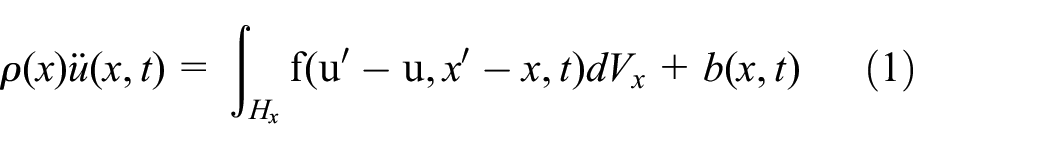
where
where

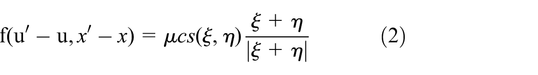
The bond force can therefore be captured by a history-dependent scalar value function

where
where

PD modeling of an EIDI system
An EIDI system generates a regular electro-impulse load on the aircraft skin through complex electromagnetic induction. The dynamic analysis object considered in this study consisted of the wing skin as a substrate and an adhered ice layer. Therefore, the pulse-force distribution law was studied and simplified for use with PD. The key to simulating the de-icing process of an EIDI system is the mechanical behavior of the ice, including its mechanical behavior under a high strain rate and ability to adhere to the substrate.
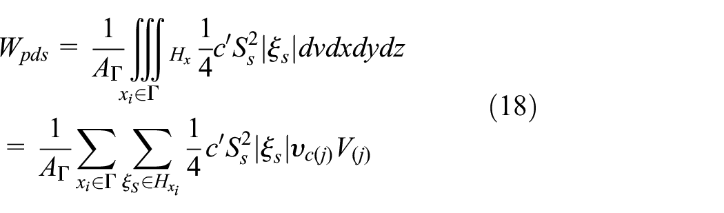
Electro-impulse load model using PD
The duration of the electro-impulse load in the model was defined as 1 ms, and its transient distribution was considered to follow a sine function with a period of 2 ms as per

where
The electro-impulse load can be transformed into a volume force

where
Ice layer–substrate PD interface model
During EIDI, ice is in a state of high strain, showing significant brittle characteristics. In this study, ice was therefore regarded as a typical brittle material. The fracture toughness of ice at
A bond series model of the ice–aluminum substrate interface was constructed based on the distance weighting of ice–ice bonds and aluminum–aluminum bonds, as shown in Figure 1. Bond A is defined as the material property of ice and bond B as the material property of aluminum. Assuming that the lengths of bonds A and B in the initial configuration are
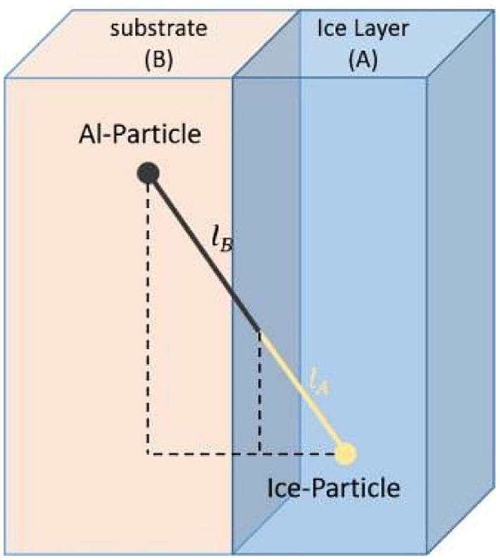
Ice–substrate interface model.
Construction of ice–aluminum substrate bond force function
In the distance-weighted bond series interface model, the internal forces of the ice–ice bond and aluminum–aluminum bond are equal:


where
The bond constant of the interface bond can be obtained using equations (9) to (12) as follows:
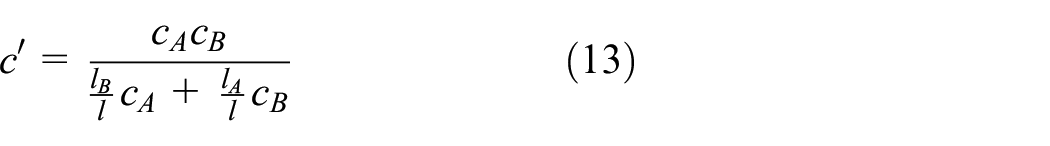
Equation (13) has rotational symmetry for the subscripts A and B, so the distance weighting function is introduced to simplify the expression using:

which yields

Therefore, the bond force of the interface bond can be expressed as the following function:

where

Determination of critical elongation
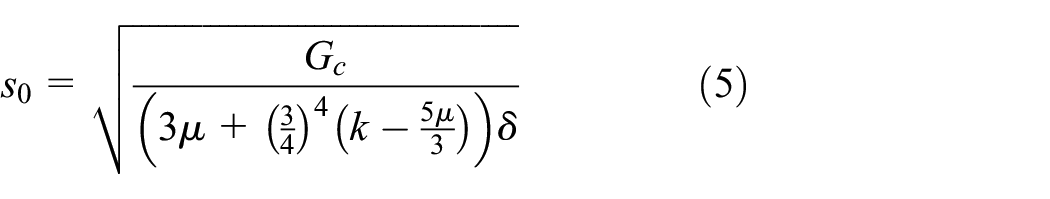
The spatial integral for the critical energy of the PD bond, which occurs when it reaches the critical elongation
The ice–aluminum substrate interface model based on the weight function series is able to effectively reflect the stress–strain relationship of the interface in all directions, noting that the adhesive strength of the ice on the substrate is anisotropic. The adhesive tensile strength across this interface
In its initial configuration, the ice-aluminum mixed bond can be divided into the two types shown in Figure 2: the bonds perpendicular to the interface are defined as interfacial tensile bonds, and the bonds crossing the interface at any other angle are defined as interfacial shear bonds. The bond constants of both bond types are the same and can be determined by the series mixed bond model; however, the critical elongation values of these bond types are different, and are denoted as
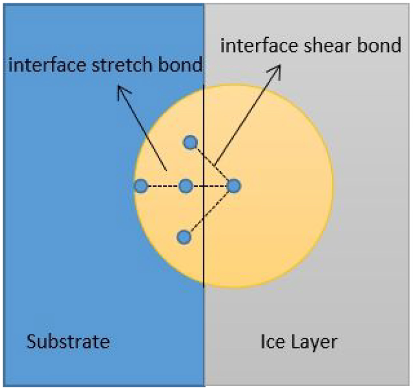
Mixed bond model of ice–substrate interface.
For the linear elastic problem, the change in the interfacial tensile bond energy owing to shear deformation is ignored, and the shear failure at the ice–aluminum substrate interface is regarded as a split-mode crack. The fracture energy of shear failure is equivalent to the energy of all interfacial shear bonds passing through the interface, and the critical elongation of the interfacial shear bond is obtained accordingly.
The energy integral for reaching the critical elongation through all the interfacial shear bonds per unit interfacial area is as follows:
where


where GS is the shear energy release rate.
The tensile failure of the ice–aluminum substrate interface is regarded as an open crack, and tensile deformation will cause a change in the bond energy across this interface that includes both the interfacial tensile and shear bonds. Therefore, the fracture energy of tensile failure is equivalent to the sum of all bond energies passing through the interface.
The energy integral when reaching critical elongation through all interfacial tensile bonds per unit interfacial area is expressed as follows:

where


Damage model
In the PD model of the EIDI system established in this study, the interaction between the material points can be divided into three categories: the interaction between the material points within the ice layer and those within the aluminum substrate, which are defined according to the ice–ice bond and the aluminum–aluminum bond, respectively, and the interaction between the layers through the interfacial bonds (tensile and shear), which are used to characterize the peeling damage between the ice layer and the aluminum substrate. Therefore, the exfoliation rate of ice material points can be defined by

When
Numerical study and validation
Model parameters of EIDI system
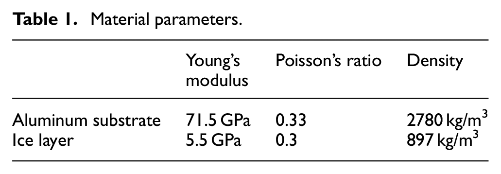
In the numerical simulation conducted in this study, the aluminum substrate was 420 mm square, 2 mm thick, and covered with a 3 mm thick layer of ice. The material parameters of the aluminum and ice are listed in Table 1. For boundary conditions, two adjacent edges of the aluminum substrate were clamped as shown in Figure 3. The electro-impulse excitation was simulated by applying an excitation force to a 60 mm diameter circular area in the center of the substrate. The PD model node spacing
Material parameters.

Model of electro-impulse de-icing system.

Flow chart of PD numerical analysis.
Numerical simulation
Model verification
Figure 5 compares the results of the PD model established in this study with the finite element and experimental results obtained by Guo, 20 in which it can be observed that the PD model can more reasonably reflect the ice breaking phenomenon in the process of EIDI. Furthermore, the PD model clearly shows ice crack initiation and intuitively shows the crack propagation path and failure form.
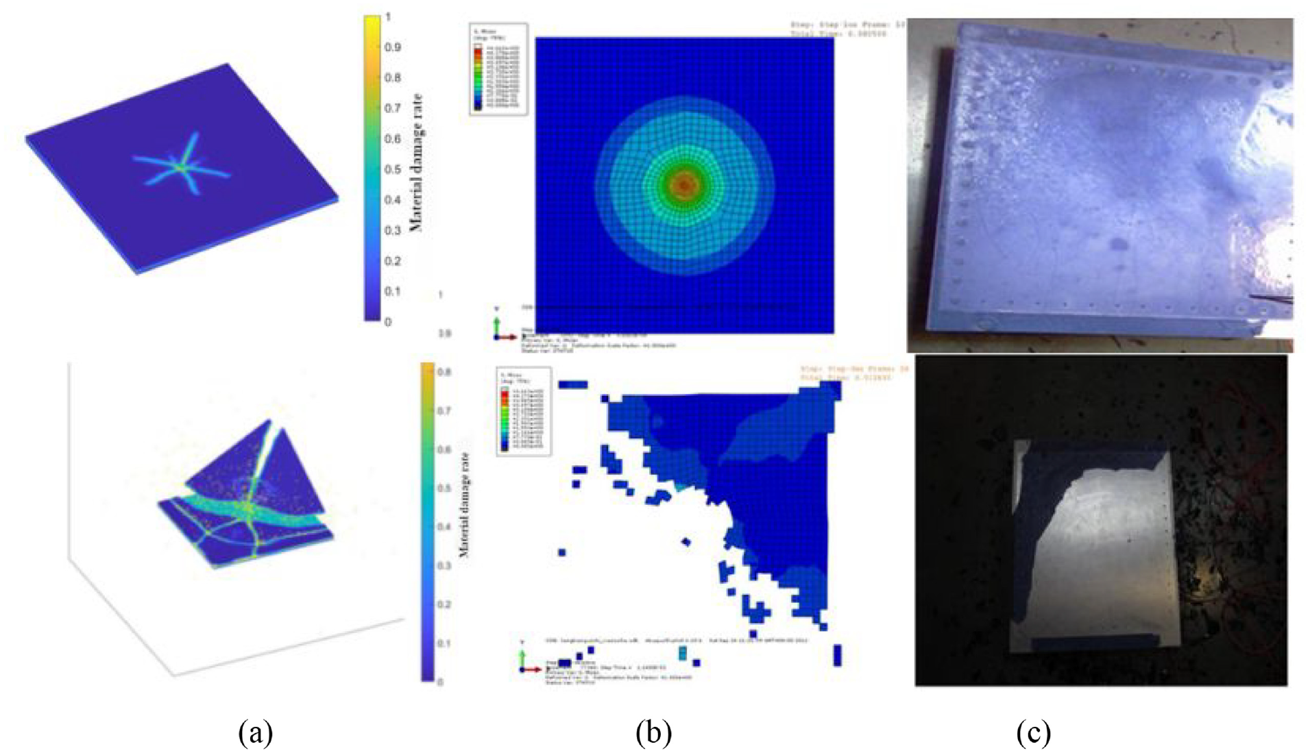
Dynamic analysis of de-icing using the bilateral constraint model
The dynamic response of the bilateral constraint model is illustrated in Figure 6. After time T = 5 ms, the damage and peeling of the ice layer tended to be stable. In the end, only a small amount of ice remained in the area along the fixed edges, so the de-icing effect was significant. Under the action of the electro-impulse load, the substrate deformed significantly in the central region, where the initial cracks appeared then developed into five main cracks, one of which eventually extended along curved paths to each of the four edges and one of which extended to the free corner along the diagonal line of the substrate. The cracks extending to the free edges eventually led to the fragmentation and peeling of several ice layers. As the deformation of the structure near the free edges increased, when T = 1.55 ms, two new cracks were generated in the undeformed areas of the two free edges that penetrated the ice and eventually converged, stripping the enclosed ice layer.
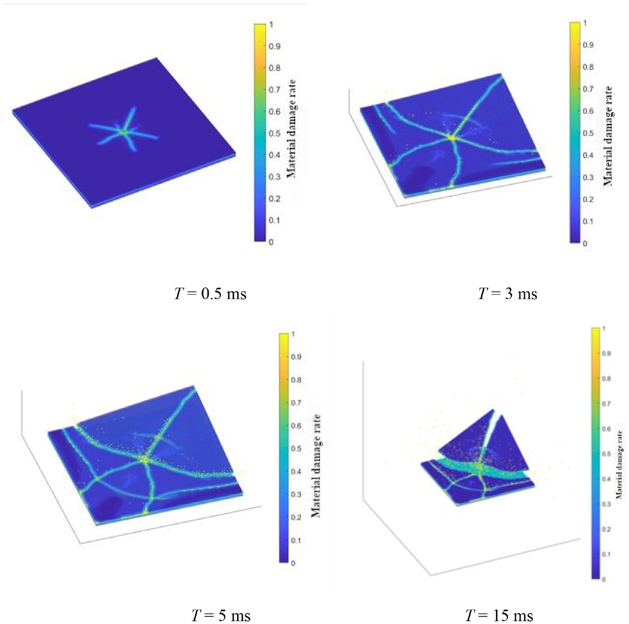
Crack growth of ice layer in bilateral constraint model.
A transient analysis of the ice layer as it peeled off the substrate is shown in Figure 7. Because the ice layer thickness in the model was only 3 mm, the ice layer peeling evolution law was consistent with the crack propagation form on the ice surface. This phenomenon can be explained that PD discretizes matter into a series of material points and describes the interaction of these material points within a certain range as nonlocal interaction, and the results are obtained that the cracks extending to the free edges eventually led to the fragmentation and peeling of a part of the ice layer. Compared to the ice crack propagation shown in Figure 6, it can be observed in Figure 7 that a large part of the ice remaining on the aluminum substrate was intact but separated from the skin, so the ice peeling rate was not intuitively related to the proportion of the ice remaining atop the skin. The progressive damaging is blossom with flowers hich represents that the damage degree is gradually increased. The crack growth of the ice layer is gradually expanded, which indicates the importance of the safeguard procedures for reducing the crack. The ice process and the peeling off process, which are related to the progressive damaging, is also gradually expanded, which like the blossom with flowers. The two process represents the degree of the crack growth of the ice layer, which is gradually increased.

Ice stripping from bilateral constraint model.
The change in the ice stripping rate over time during and following the application of the EIDI system is shown in Figure 8. The ice layer at the began to peel from the substrate at 0.39 ms, and the stripping rate of the ice layer then increased sharply over the remaining 1 ms action time of the electro-impulse load. After the electro-impulse excitation disappeared, the ice layer vibrated freely with the skin, causing the ice layer stripping rate to continue gradually increasing. At 5.75 ms, the ice layer stripping rate reached 85.76%, after which the value tended to be stable; the final ice layer stripping rate was 86.04%.

Change in ice stripping rate over time.
As the stress concentration in the substrate is directly reflected by its strain energy density, the distribution of strain energy density in the substrate is shown in Figure 9 throughout the de-icing process. The application of the electro-impulse load clearly increased the strain energy density in the substrate near the load center, corresponding to increased ice cracking. When the electro-impulse load was stopped after 1 ms, the strain energy density in the substrate gradually dissipated with ice damage and peeling.

Nephograms of strain energy distribution in aluminum substrate.
Conclusion
In this study, the EIDI process was simulated using bond-based PD theory. The application of the method of near-field dynamics enables us to intuitively see that under the action of electro-impulse load, initial cracks appeared in the center of the substrate specimen where the load was applied, forming five main cracks that eventually extended to the four edges; one of these cracks extended to the free corner following the diagonal line of the plate. The cracks extending to the free edges eventually led to the fragmentation and peeling of a part of the ice layer. These results illustrate the manner in which the EIDI process removes ice from the surface of an aircraft wing and indicate that the proposed use of PD theory to model EIDI is valid and accurate.
Note that the application of the PD model to study the EIDI system was limited in this study to the damage problem under single excitation. Furthermore, the bond-based PD theory employed assumes that the interaction between a pair of particles is equal and reverse, which leads to the fixed Poisson’s ratio problem. Therefore, an improved bond-based PD method should be considered in future research to conduct an in-depth study of aircraft EIDI systems.
Footnotes
Handling Editor: Chenhui Liang
Declaration of conflicting interests
The author(s) declared no potential conflicts of interest with respect to the research, authorship, and/or publication of this article.
Funding
The author(s) disclosed receipt of the following financial support for the research, authorship, and/or publication of this article: Authors gratefully appreciate the support of the Fundamental Research Funds for the Central Universities (NWPU-310202006zy007), the Open Fund of Key Laboratory of Icing and Anti/De-icing (Grant No. IADL20200105).
Data availability statement
No date were used to support this study.