
Abstract
In this paper, the discrepancy between the calculated and actual fatigue life distribution trend of the axles of railway vehicle structures is corrected. The calculations were made using the traditional fixed-axle model in which the wheelset rotation is neglected in random vibration analysis. A correction method is proposed, which is based on the original methods of fatigue life analysis of the axle structure of railway vehicles (i.e. the pseudo-excitation method and finite element model) and according to the characteristics of the symmetrical axle structure and the actual rotational operation state of the railway vehicle wheelset. Taking a locomotive system as an example, the minimum fatigue life calculated by the fixed-axle model is only 0.81 million km. In contrast, the minimum fatigue life calculated by the proposed method is 5.85 million km, which is consistent with the actual fatigue life of the axle. The position of the minimum fatigue life is also consistent with the actual position. The reliability of the proposed method for calculating the random fatigue life of the axle structure is illustrated. The influence and contribution of the prestress generated by axle press-fitting and vehicle serving weight of the railway vehicle acting on the axle on the axle fatigue life were studied. The results show that the prestress has a different influence on the fatigue life reduction of the wheelset. The minimum fatigue life reduction can reach 16.68% when all the prestresses are considered. Therefore, the influence of prestress should be considered in the design of railway vehicle axle structures. The idea of considering prestress should be proposed when revising axle standards.
Introduction
The wheelset is an important part of the running gear of railway vehicles. It consists of an axle and wheel interference assembly, and has a direct effect on vehicle driving safety. In 1998, a high-speed train accident in Germany was caused by fatigue crack propagation in the axle.
Most fatigue cracks in the axle occur in the wheel seat owing to the rotation of the axle, axial tension and compression of the section load of the axle that constantly changes under the action of the load at the axle box. The cyclic action on the contact surface of the axle and wheel leads to fatigue failure. 1
According to recent enterprise statistics, in addition to wear and other damage caused by locomotive axle fatigue, approximately 2/3 of axle damage is caused by fatigue, of which more than 90% is due to fretting fatigue cracks on the wheel seat of the axle.
According to the standard, the design of railway vehicle axles should be based on the safety factor method of component fatigue strength.
Mi and Li 2 based on the elastic mechanics theory and considering the strained status and distribution of the load, established a physical model to calculate the axle strength and proposed methods for calculating the stress concentration coefficient, safety coefficient and allowable stress.
Martínez–Casas et al. 3 described a method to calculate the dynamic stress in railway axles resulting from train–track interaction based on the numerical simulation of the dynamic interaction between a flexible wheelset and flexible track.
Pokorný et al. 4 focused on the numerical estimation of the residual fatigue lifetime of railway axles, considering several different load spectra taken from the literature in the estimations. The influence of the discretisation level of the continuous load spectrum and the effects of the magnification or diminution of the load spectrum on the calculated residual fatigue lifetime of the railway axle were determined.
Noh et al. 5 evaluated the accuracy of stress intensity factor predictions using finite element analysis.
Makino et al. 6 proposed a method for estimating the fatigue damage caused by variations in in-service conditions. To clarify the S–N curve of axles, full-scale fatigue tests were performed on railway axles used in Japan.
Wu et al. 7 developed a stepwise fatigue assessment method that incorporated the nominal stress and damage tolerance with four key technologies: the improved principle of sample polymerisation, uniaxial tensile-based crack growth model, stress-defect-lifetime assessment diagram and surface residual stress reconstruction. The changes in design concepts due to axle materials as well as the limitations of quantitative and highly conservative theoretical approaches in the safety assessment of axles (EA4T and S38C) were also analysed.
Researchers have considered the effects of random excitation on structural fatigue.
Salari 8 investigated fatigue crack growth under random loading using analytical methods.
Kebir et al. 9 studied fatigue under random loading using the same concepts as constant loading with the addition of damage summation.
Because of the difficulty in directly measuring the dynamic stress of a high-speed rotating axle, researchers have used indirect experimental methods.
Mädler et al. 10 described an experimental method for determining the residual lifetime of wheelset axles. They conducted crack propagation tests on a complete wheelset installed in a full-scale wheel–rail roller test rig using a measured load spectrum.
Liu et al. 11 carried out low- and high-cycle rotating bending fatigue tests and a crack growth rate test on EA4T alloy steel to study the fatigue strength and service performance of railway axles with inside axle boxes (RAlBs). The difference between the critical safety position of RAIBs, traditional railway axles and outside axle boxes (RAOBs) was analysed. Defects inevitably occur on the axle surface during transportation or service. High stress concentration at the defects creates the ideal condition for crack initiation and propagation, which significantly reduces the fatigue life of axles. When the crack depth at the critical safety position of the axle extends to 5 mm, the residual lives of RAIBs and RAOBs are only 0.32 and 0.20 million km, respectively.
Narayanan 12 proposed probabilistic models to study the fatigue life of a casted structure with porosity effects in aero-engine applications.
Li et al. 13 investigated the fatigue life of an automobile stabiliser bar using the durability bench test. Researchers have carried out research using a combination of numerical and experimental methods.
Náhlík et al. 14 proposed a methodology for predicting the residual fatigue lifetime of a railway axle based on the concept of linear elastic fracture mechanics. The methodology includes estimating the critical position of the initial crack, predicting the fatigue crack front shape development during crack propagation, separating the bending and press-fitting contributions to the axle load, experimental measurement of the crack growth kinetics of EA4T steel and estimating the residual fatigue lifetime of the railway axle.
Maglio et al. 15 investigated the effects of evolving rolling-contact fatigue damage on a passenger train wheelset using a combination of instrumented wheelset measurements and numerical simulations of axle bending stress.
With the development and improvement of the finite element method, researchers have applied the method in axle fatigue analysis.
Son et al. 16 evaluated the fatigue life of hollow railway axles with tapered bore surfaces in accordance with the European Standards EN13103 and EN13261. The fatigue strength was also evaluated by finite element analysis of a full-scale axle test piece. The fatigue life analysis of the wheel–rail contact force was conducted using the dynamic simulation results of a Korean electric multiple unit (K-EMU) multi-body dynamics model.
Hamdaoui et al. 17 developed a finite element model (FEM) to reproduce the mechanical behaviour of a broken wheelset in Canadian railways.
To understand the characteristics of defects and their impact on the axle, Ren et al. 18 studied two types of defects (i.e. collision and scratching) in a certain type of axle installed in actual high-speed trains. The causes of defects, defect morphology, axle stress and strength changes were analysed in detail. FEMs of the axle with defects were established with the following software: ANSYS, HYPERMESH and FRANC3D. A finite element calculation method was employed to obtain the stress concentration factor of defects with different gap sizes. The influence of defect parameters on the axle stress was investigated.
Zhou et al. 19 conducted a stress-time test of high-speed train axles along a rebuilt railway line and the Jingjin intercity railway line. The equivalent stress along the stress spectrum was studied with the presence of notches on the axles. They found that for axles without notches, the equivalent stress was lower than the fatigue limit of smooth axle materials. However, the equivalent stress of notched axles tended to exceed the relevant fatigue limit. Therefore, for the purpose of damage tolerance design, the running environment and axle surface status of a train must be considered in axle fatigue strength design.
With the development of numerical analysis and computer technologies, it is possible to use an FEM and a random vibration method to analyse axle fatigue.
Zhao et al., 20 Huang, 21 Xu, 22 and Cao et al. 23 predicted the fatigue life and reliability of the axle of a high-speed train based on the random vibration theory and fatigue strength of the vehicle system. First, a dynamic model of the high-speed train was established. The characteristics of the vehicle running on the line were simulated, and the random load spectrum on the axle was obtained. Then, the random load spectrum on the finite element of the axle was applied to the analysis, the stress-time history of the key points of the axle was obtained, and the stress spectrum of the key points was obtained after statistical analysis. Finally, the fatigue life estimation and reliability analysis of the axle were carried out using the local stress-strain method and cumulative damage theory.
The abovementioned analysis process was based on the time-domain method of random vibration analysis. The software ANSYS and ABAQUS were adopted for the finite element analysis, SIMPACK for the dynamic analysis, and FE-SAFE for the fatigue life analysis.
Wu et al. 24 used the same process to analyse the axle fatigue life considering the wheel harmonic wear.
Zhang, 25 Liu et al., 26 Xiaoxue, 27 and Guo 28 studied the random vibration and structural fatigue in a railway vehicle system using the combined pseudo-excitation method (PEM) and finite element method to determine the vibration, stress and other responses of the main structure of a railway vehicle system under random excitation. This method is feasible for determining the fatigue of frames, car bodies and other structures, and rotating parts such as wheelsets. Although the fatigue life of wheelsets can be calculated, the results do not reflect those from the actual operation of wheelsets because the calculation is based on a fixed-axle dynamics analysis model of railway vehicles that ignores the rotation of wheelsets. Therefore, a modified axle fatigue life analysis method is proposed that considers the wheelset rotation. The method is used to analyse the fatigue life of the axle structure subjected to the random vibration of railway vehicles, and address the discrepancy between the predicted and actual fatigue life and distribution trend of the axle structure. The influence and contribution of the prestress formed by axle press-fitting and the self-gravity of the railway vehicle on the axle fatigue life are also compared and analysed.
The modified method
According to the random fatigue method for analysing the railway vehicle structure proposed in Liu et al., 26 the root-mean-square (RMS) value of the stress of all nodes of the wheelset is calculated. A cloud diagram is drawn, as shown in Figure 1. The specific location at which the maximum RMS value of stress occurs on the wheel can be seen. The RMS value of stress varied with the position on the circumference of the wheel with the same radius. Such a distribution trend of the stress RMS does not correspond with the actual operation of the wheelset.

RMS value of wheel stress.
The wheelset can be simplified as an axisymmetric structure that rotates forward during the actual operation. After the vehicle travels a sufficient distance, the circumferential length of any section of the wheelset relative to the driving distance can be ignored. The statistical values of random variables, such as the acceleration and stress of all nodes on the circumference at the same radius of any section of the wheelset, are considered to be the same after a sufficient distance. If the coordinate system of the wheelset is converted from a Cartesian coordinate system (
Stress is the basis of axle fatigue assessment. Random dynamic stress can better reflect the actual situation. The accurate determination of the stress response is key to reliable structural fatigue assessment. Therefore, the statistical value must be equivalent to the angle-independent statistical value:

where
The frequency domain method of fatigue evaluation based on random stress is based on the miner’s fatigue damage accumulation theory:

where

where
Each node on the circumference with radius
where

where
In the process node

where
Then, the total number of stress cycles

where
Any node on the circle repeats this process again and again; hence, the number of stress occurrences

where
According to the Miner fatigue damage accumulation theory, the accumulated damage at time

where
Therefore, if the stress occurrence rate
Numerical example
Taking a certain type of locomotive as the calculation model, the FEM of the locomotive body and frame is shown in Figures 2 and 3.

Finite element model of the carbody of a locomotive.

Finite element model of the bogie of a locomotive.
Figure 4 shows the FEM of the locomotive wheelset. The total number of nodes of the locomotive system is 57,143, the specific parameters are shown in Table 1. The calculated locomotive running speed is 120 km/h. The power spectrum of track irregularity adopts the American level 6 spectrum.
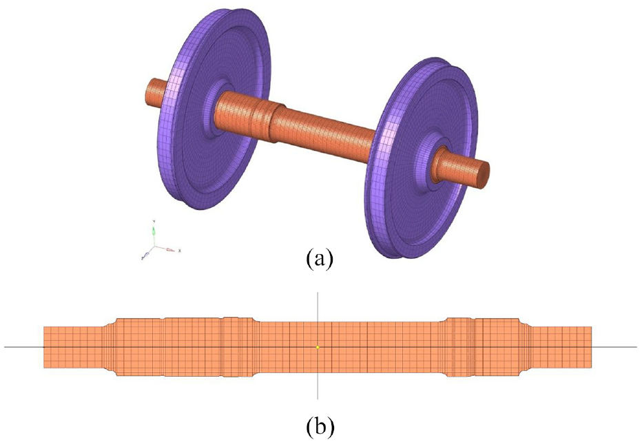
Finite element model of locomotive wheelset: (a) wheelset and (b) front view of axle.
Parameter of FEM of locomotive.

The distribution trend of axle fatigue life calculated by the original method is shown in Figures 5(a) and 6(a). The fatigue of the axles and wheels calculated using the fatigue calculation correction method proposed in this paper are shown in Figures 5(b) and 6(b). The figures show the fatigue life distribution trends of the cross-section along its own axis where the fatigue life of the wheelset is the shortest.

Fatigue life distribution of axial section at minimum fatigue life of axle: (a) not amended and (b) amended.

Fatigue life distribution in the transverse section with minimum fatigue life of axle: (a) not amended and (b) amended.
The location at which the locomotive axle fatigue life is shortest is colour red, as shown in the figures. There are mainly two mating surfaces between the axle and the inner side of the two wheelsets, which is consistent with the actual location of fatigue damage of the axle. This shows that calculating the axle fatigue based on the PEM can accurately predict the key position of the axle prone to fatigue damage.
However, the axle fatigue life distribution is non-axisymmetric. The minimum life is only 0.81 million km, which is far less than the actual fatigue life of a locomotive axle.
The fatigue life results of the corrected locomotive axle are shown in Figure 5(b). The fatigue life distribution of the axle shows an upward and downward symmetrical trend. The corrected minimum fatigue life is 5.8525 million km, which is consistent with the actual fatigue life of the axle. The position where the minimum life of the axle did not change remains the mating surface between the axle and inner side of the two wheelsets. This shows the reliability of calculating the fatigue life of the railway vehicle axle using the correction method proposed in this paper combined with the PEM.
According to the fatigue life distribution at the cross-section and the minimum fatigue life of the locomotive wheels shown in Figure 6(a), the fatigue life distribution in this section is only left-right symmetrical, and the specific position at the minimum fatigue life of the wheels can be determined.
The fatigue life results in this section after the correction are shown in Figure 6(b). The fatigue life distribution exhibits an axisymmetric trend. The radius position where the wheel has the lowest fatigue life has not changed, which fully reflects the fatigue life trend in line with the actual operation of the wheel.
According to the overhaul regulations for this type of locomotive, the cycle with the highest-level maintenance (C6) is 2 million km or 12 years, which translates into an average annual operating distance of 167,000 km. The life of a locomotive is 30 years, which is converted into the corresponding operating mileage as 30 × 16.7 ≈ 5 million km. Therefore, the minimum service life of the axle structure calculated by the proposed method is in line with the axle operation requirements of this type of locomotive.
In summary, the random fatigue analysis of locomotive wheelsets can be realised by using the PEM combined with an FEM. The life at any position of the wheelset can be calculated, which fully reflects the fatigue life distribution trend. However, when the actual wheelset rotation is not considered, the calculated minimum life and distribution of the wheelset do not agree with the actual situation, but it can accurately predict the key position of the wheelset that is prone to fatigue damage.
Using the proposed correction method that considers the wheelset rotation, the correction was carried out on the basis of the response obtained by the PEM. Thus, the calculated minimum life and distribution of the wheelset are in line with the actual situation, which shows the reliability of the proposed correction method and provides theoretical guidance for wheelset design and flaw detection.
Influence of prestress on axle fatigue
In the actual operation of railway vehicle wheelsets, in addition to the rotation considered in the previous section, prestress is also generated by the axle press assembly in the wheelset structure and the vehicle servicing weight acting on the axle.
Prestress generation will inevitably convert the random stress of the wheelset structure into a non-zero mean random variable. Many studies have shown that increasing the mean stress decreases the fatigue limit of the material. Wheelset fatigue evaluation based on the PEM proposed in the previous section assumes that the random stress of the structure is a zero-mean process. Therefore, it is necessary to consider the factors influencing the prestress and correct the stress amplitude during the fatigue assessment of railway vehicle wheelsets so that the assessment process can be more in line with the application situation. 29
In this study, the Goodman curve equation was used for equivalent transformation, considering the influence of the average stress on the structural fatigue performance. The asymmetric cyclic stress is equivalent to the symmetric cyclic stress according to the equal damage principle. The Goodman linear model is expressed as

where


where

Applied to this method, it is equivalent to the original obtained stress power spectrum

where the superscript “*” indicates the complex conjugate, and the superscript “
The proposed method in this paper is based on the two-dimensional plane FEM for analysing the press-fitting process of a locomotive axle in which the interference is 0.32 mm.
To fully and accurately reflect the stress state in the press-fitting process of the contact part between the axle and wheel, the FEM grid of the contact part was densified, with a grid size of 5 mm. At the same time, considering the calculation efficiency, other non-key analysis parts of the wheelset were divided into coarse grids, as shown in Figure 7.

Two-dimensional finite element plane model of wheel-pair.
Based on this model, a three-dimensional FEM of a locomotive wheelset was generated and applied to the calculation of the axle fatigue life. As shown in Figure 8, the total number of nodes is 528,255, of which 393,919 are on the axle.
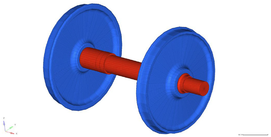
Three-dimensional finite element model of wheel-pair.
Using the prestress correction method proposed in this section and the correction method considering the wheelset rotation from the previous section, as well as the gravity of the structure itself with a total weight of 100 tons and the factors of press assembly, the axle fatigue life in the four schemes is calculated as follows:
Scheme 1: no prestress correction;
Scheme 2: only the prestress caused by the gravity of the structure is corrected;
Scheme 3: only the prestress generated by axle press-fitting and assembly is corrected;
Scheme 4: prestress correction caused by the joint action of gravity and press-fitting assembly.
The results are shown in Figures 9 to 12. The minimum fatigue lives of the locomotive axle are listed in Table 2.

Fatigue life of prestressed unmodified wheel shaft.

Fatigue life of prestressed modified wheel axle by gravity factor.

Fatigue life of prestressed modified wheel shaft by compression assembly factor.

Fatigue life of prestressed modified wheel axle by gravity and compression assembly factors.
Minimum fatigue lives of axle under prestress.

The wheelsets in Figures 4 and 8 correspond to the same model. The only difference is that the FEM is divided with different precision. The FEM of the wheelset in Figure 4 is divided with a 20 mm mesh as a whole. The FEM of the wheelset in Figure 8 is divided with a 5 mm mesh at the contact position between the axle and wheel.
In Figures 5(b) and 9, the minimum fatigue life of the axle is 5.85 and 6.23 million km, respectively. The 6.53% increase indicates that the mesh refinement of the FEM affects the fatigue life calculation of the locomotive axle.
Figures 9 to 12 show the fatigue life nephogram of the contact position between one end of the locomotive axle and the wheel. The minimum fatigue life position of the axle in the four schemes did not change, which occurs inside the contact position with the wheel (left in the figure). However, in schemes 2, 3 and 4, the minimum fatigue life of the axle decreased, indicating that the prestress generation had no effect on the minimum life position, but had different effects on the reduction of axle fatigue life.
There was no significant change in the area of the low life area (>10 million km) in schemes 2 and 1. The minimum life of the axle slightly decreased by 2.33%, indicating that the prestress generated by the gravity of the structure had little effect on the fatigue life of the axle.
The area of the low-life area in schemes 3 and 1 showed an obvious increasing trend. The minimum life of the axle decreased by 13.83%, indicating that the prestress generated by the axle press assembly had a significant impact on the axle fatigue life, which should be considered in fatigue evaluation.
There was no obvious change trend in the area of low-life area in schemes 4 and 3. The minimum life of the axle slightly decreased by 3.31%, but the pair reduction was 16.68% compared with scheme 1. This shows that although the prestress generated by the axle press-fitting assembly was the dominant factor in the reduction of axle fatigue life, the gravity and press-fitting factors must be considered simultaneously in fatigue assessment.
The minimum fatigue life evaluation results of locomotive axles are listed in Table 1. It can be seen among the four schemes that when the prestress of the contact surface is not considered, the fatigue life is the longest. When all prestresses are considered, the fatigue life is the shortest. Therefore, the influence of prestress on fatigue life is still very obvious.
At present, China’s TB/t2395-2008 design method for power axles of railway rolling stock adopts the safety factor method of allowable stress; specifies different allowable stresses and safety factors for different materials and sections of axles; and determines the section size of axles in combination with practical application experience.
The impact of axle interference on axle life is ignored. The main reason for this is that the wheelset is a very important safety component, and a conservative design can tolerate more uncertain and unknown factors. The impact of interference on axle life belongs to this type of situation.
Therefore, the influence of the press-fit interference stress on the axle fatigue life cannot be ignored. It is suggested that prestress be considered in axle design. Although prestress is not considered in the current design standard, its inclusion should be proposed.
Conclusion
This paper aims to address the following situation: owing to the fixed-axis model, the fatigue life of rotating parts (e.g. axles) calculated by the previously proposed method (i.e. the combined random fatigue analysis method of railway vehicle system structure based on a FEM and the PEM) is inaccurate. A modified method for calculating the axle fatigue life that considers the wheelset rotation is proposed based on the dynamic stress response calculated by the previously proposed method.
A comparison with relevant data in relevant railway vehicle overhaul regulations verified that the proposed method is reliable for axle fatigue life evaluation. The effects of the press-fit prestress on the contact surface between the wheel and axle in the wheelset, and the prestress under the serving weight of the entire vehicle on the fatigue of the axle structure were analysed.
The main conclusions are as follows:
Random fatigue calculations were carried out for the wheelset of a locomotive system. The minimum life calculated by the fixed-axle model was only 0.81 million km, while the minimum life calculated by the proposed correction method was 5.85 million km, which is consistent with the fatigue life of the actual axle. The position of the minimum fatigue life of the wheelset is also consistent with the actual position.
The minimum fatigue life calculated using the rough and fine FEMs of the same type of wheelset are 5.85 and 6.23 million km, respectively. The 6.53% increase indicates that the mesh refinement of the FEM affects the fatigue life calculation of the wheel.
The minimum fatigue life position of the locomotive axle occurs inside the contact position between the axle and wheel. The serving weight of the entire vehicle and the prestress generated by press-fitting have no effect on the minimum fatigue life position of the wheelset.
Prestress has different effects on the reduction of the wheelset fatigue life. The reduction results from considering only the vertical servicing load. By considering the press-fit prestressing, all the prestresses were found to be 2.33%, 13.83% and 16.68%, respectively. Therefore, the influence of prestress on fatigue life cannot be ignored, and the must be considered in the design of locomotive axles. The idea of considering prestress should be proposed when revising axle standards.
Footnotes
Acknowledgements
The authors acknowledge the support from the CRRC Qiqihar Rolling Stock Co., LTD and CRRC Datong Co., LTD.
Handling Editor: Chenhui Liang
Declaration of conflicting interests
The author(s) declared no potential conflicts of interest with respect to the research, authorship, and/or publication of this article.
Funding
The author(s) disclosed receipt of the following financial support for the research, authorship, and/or publication of this article: Key projects of science and technology research and development plan of CRRC Corporation Limited. Task number: 2021CHB283. The Research Project of National Innovation Center of High Speed Train Task Number: CXKY-02-01-01(2020).