
Abstract
To aid in addressing global climate change and reduce automobile carbon emissions, the thermal efficiency of engines must be improved. By altering the structural design of an engine body (including the cylinder blocks and cylinder heads), a rapid combustion model with a compression ratio of 16 and a maximum tumble ratio of 3.94 was developed that improved the combustion speed. Through synergistic matching of cooled exhaust gas recirculation with lean burn technology, when the exhaust gas recirculation rate was 20% and the air-fuel ratio was 20, the effect of reducing NOx emission and knocking reached the optimum level. When an electronic water pump and dual thermostat technology were used, the temperature change at the combustion chamber wall of each cylinder was <3%, and when the engine ran at speeds of up to 2400 r/min and torque of up to 60 Nm, the coolant temperature could reach 105°C, thereby reducing both heat dissipation and friction losses. The maximum thermal efficiency of the new DHE16GDI engine developed based on the DAM16N engine model increased by approximately 4.4%, and the contents of the major pollutants NOx and CO and the total hydrocarbon content were reduced by approximately 43.1%, 34.8% and 8.3%, respectively.
Keywords
Introduction
The CO2 emitted by human industrial production and general living causes climate change, which in turn affects human health and the ecosystem balance (Figure 1). 1 In response to global climate change, numerous countries have reached a consensus on achieving net-zero CO2 emissions. 2

Human activities and their effects.
The carbon emissions caused by energy use are mainly produced by the electricity, heating, transportation and construction industries. Among these industries, the transportation industry is highly dependent on fossil fuel use. Until 2021, 92% of transportation energy requirements were met by oil-based fuels, and the resulting CO2 emissions accounted for approximately 21% of the total global carbon emissions. 3 The modes of transport used in this industry mainly include road transportation, air transport, railway transport, and shipping. Among these transport modes, the CO2 emissions from road traffic account for approximately 75% of the emissions of the entire transportation industry, making road traffic a main contributor to climate change. 4
Gasoline and diesel engines are the main engine types used in road transportation and the resulting CO2 emissions are related directly to oil consumption. According to the chemical reaction equation, when 1 L of gasoline is burned completely, it produces approximately 2.3 kg of CO2 (density = 0.745 kg/L), and complete combustion of 1 L of diesel produces approximately 2.63 kg of CO2 (density = 0.845 kg/L). Therefore, to reduce fuel consumption, enhance the potential for both energy conservation and emission reduction, and achieve a sustainable social environment, technical research must be conducted on improvement of the thermal efficiency of engines.
The effective thermal efficiency (ηet) of an engine represents the ratio of the effective work of an actual cycle to the heat consumed to perform this effective work. This efficiency is an essential indicator used to measure the economic performance of engines. 5
As a result of increasingly strict emission regulations and growing ecological awareness, the thermal efficiency of mass-produced gasoline engines has continued to increase (Figure 2). According to a statistical analysis of the maximum thermal efficiency of mass-produced 1.5- to 2.0-L engines since 2018, the maximum thermal efficiency of traditional engines lies mainly between 37% and 40%, while that of hybrid electric vehicle (HEV)-specific engines has reached 41% to 43%. The thermal efficiency of the HEV-specific engine is higher than that of the traditional engine, mainly because an HEV can compensate for the power demands of the entire vehicle by adjusting the drive motor torque to ensure that the engine always works in the most economical fuel consumption load area.6–8
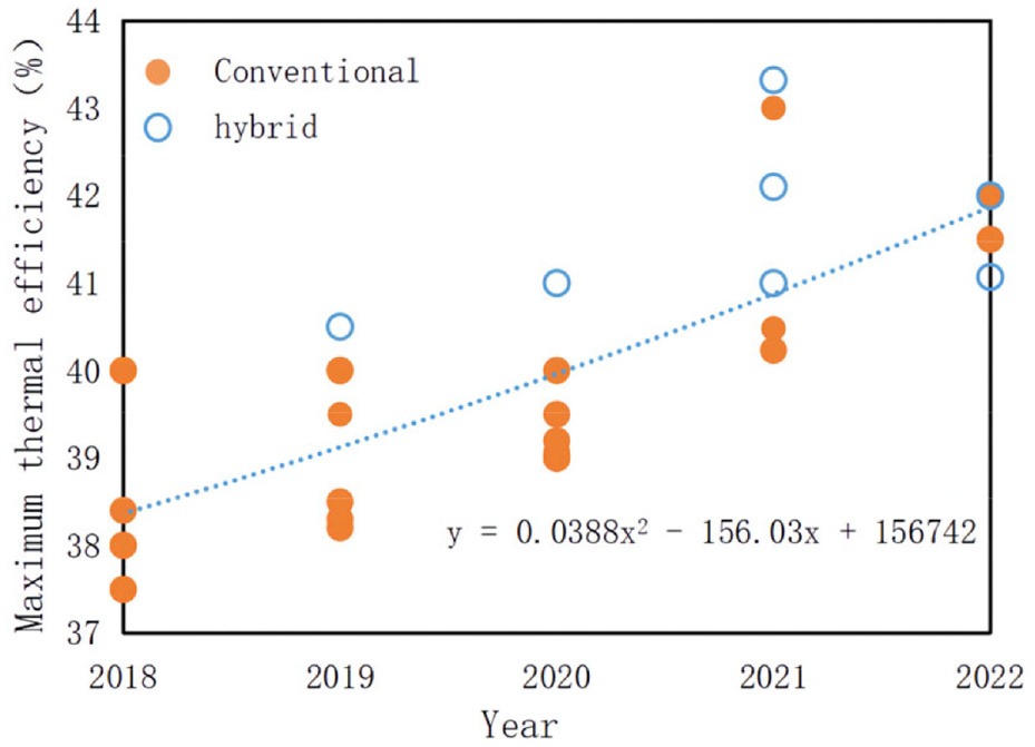
Current situation and trend for maximum thermal efficiency of mass-produced gasoline engines.
From an engineering thermodynamics perspective, the theoretical thermal efficiency of an engine is proportional to both the expansion and specific heat ratios, which can be improved by increasing the compression ratio (CR) and using a lean burn mode, respectively. However, these ratios are affected by factors such as the engine structure, knocking and friction. 9
In the actual working processes of engines, the heat released through complete combustion of the fuel mainly corresponds to the effective work, exhaust losses, cooling losses, mechanical losses, and unburned fuel and radiation losses. 10 Therefore, reducing the loss of each engine part provides an effective approach to improve the thermal efficiency of engines. This paper is based on the route used to perform a technical upgrade of the DAM16K engine (Harbin Dongan Automobile Power Co., Ltd., Harbin, China) and represents a technical study on improvement of engine thermal efficiency.
The main parameters of the DAM16K engine when installed on light commercial vehicles such as those produced by Foton, Dongfeng and Changan include a CR of 11.5, use of exhaust gas recirculation (EGR), the Atkinson cycle and dual variable valve timing (DVVT), and a maximum thermal efficiency of 37% (Figure 3). On the basis of the DAM16K engine, the DAM16N engine was developed, in which the CR was increased to 13 and the stroke length was increased to raise the stroke-to-bore (S/B) ratio to 1.26. At the same time, technologies such as cooled EGR, low friction and efficient cooling were used to obtain the maximum engine thermal efficiency of 39.5%. The long stroke design reduces the ratio of the piston surface area to the combustion chamber volume when the piston is at top dead center, thus reducing the cooling losses. 11 Cooled EGR can not only reduce the maximum combustion temperature, knocking and NOx emissions, but also can reduce pumping losses. Cooled EGR is thus becoming a current mainstream technology. 12

Technical route for thermal efficiency improvement of the DAM16K engine.
To meet the more stringent fuel consumption regulations that will apply in the future, the hybrid dedicated engine DHE16GDI is being developed to have higher thermal efficiency, and this represents a new challenge. In combination with the main technical application of the DAM16N engine, by using the same gasoline and oil and theoretically improving the compression and specific heat ratios, a rapid combustion model with high compression and tumble ratios was designed in this study by changing the engine body structure, which can then be used to reduce both the cooling and exhaust losses. A reasonable matching scheme for lean burn and cooled EGR technology was studied to mitigate knocking and unburned fuel and radiation losses. Electronic water pumps and dual thermostats were used to achieve uniform cooling and reduce the cooling and mechanical losses.
Engine overview
An engine’s thermal efficiency is inversely proportional to its fuel consumption rate. The formula used to calculate the effective thermal efficiency is given as follows: 5

where be is the effective fuel consumption rate, which has units of g/(kW·h); and Hu is the low calorific value of the fuel used, which is 42410 kJ/kg.
For the DAM16N engine, the minimum fuel consumption range is achieved at speeds in the 2000- to 2800-r/min range and at torques of 90 to 110 Nm, while the lowest fuel consumption is 214.92 g/kWh at 2400 r/min and a torque of 103 Nm (Figure 4(a)). Under the same boundary conditions, i.e., at 2400 r/min and 103 Nm, minimum fuel consumption experiments at CRs ranging from CR13 to CR18 were conducted while satisfying the knocking requirements and the maximum thermal efficiency was then calculated. When CR16 was used, the thermal efficiency improvement rate reached its maximum value, which was approximately 2.45% higher than that of the DAM16N (Figure 4(b)).
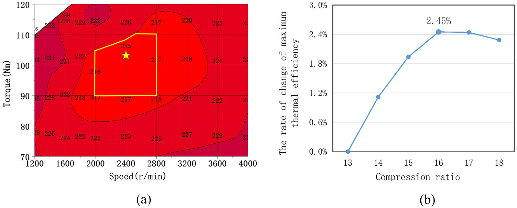
Influence of the CR on the thermal efficiency.
The strokes and the cylinder bores of the 1.5- to 2.0-L mass-produced and pre-researched engines were calculated, with results as shown in Figure 5. The analysis showed that as the cylinder diameter gradually decreased, the stroke gradually increased in tandem, and the S/B ratio also increased gradually. The S/B ratio of mass-produced engines is approximately 1.2, while that of the pre-researched engines is above the trend line shown in the figure. For example, the S/B ratio of the DAM16N engine is 1.26, which is above the trend line and is indicated by the red five-pointed star.

Bore and stroke statistics for batch-produced and pre-researched engines.
In addition to its high CR, long stroke, and structural optimization, the pre-researched DHE16GDI engine also applies technologies such as lean burn, cooled EGR, 350-bar direct injection, and uniform cooling. A detailed comparison of the DAM16N engine parameters with the parameters of the DHE16GDI engine is presented in Table 1.
Comparison of basic engine parameters.
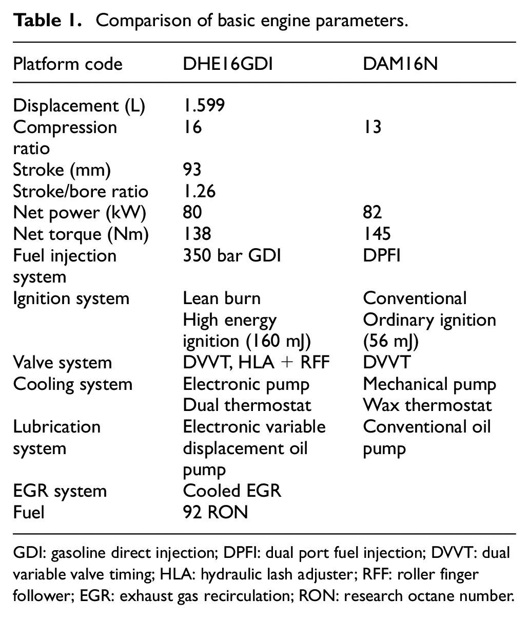
GDI: gasoline direct injection; DPFI: dual port fuel injection; DVVT: dual variable valve timing; HLA: hydraulic lash adjuster; RFF: roller finger follower; EGR: exhaust gas recirculation; RON: research octane number.
Experimental apparatus
All experiments were conducted in this study using the same test bench and equipment. The engine test system structure (Figure 6) mainly included an engine bench, a dynamometer, a motor control cabinet and a console.

Engine bench test system.
To ensure test accuracy, experimental equipment manufactured by AVL was mainly used. The specifications and accuracy figures of this equipment are presented in Table 2.
Experimental equipment information.

FS: full scale; RH: relative humidity.
The test conditions for the engine on the test bench were as follows: SAE SN 0W-20 grade oil was used, the ambient temperature was 25°C ± 2°C, the intake air humidity was 40% to 60%, and the engine water temperature was 90 to 115°C. The inlet pressure drop at the rated power point was ≤3.0 ± 0.5 kPa, the exhaust back pressure was ≤40 kPa, and the exhaust temperature was ≤880°C.
Improvement of the engine thermal efficiency
Rapid combustion technology
By optimizing the intake port, the combustion chamber (including the cylinder head, the cylinder block, and the piston top) and other structures in the engine, and using a precise arrangement of the spark plugs and fuel injectors, reasonable airflow movement was ensured, the mixture tumble ratio and the turbulence intensity were improved, and fast burning was promoted.
The intake duct design is shown in Figure 7. First, the lower half of the airway was designed to have a fish-belly shape and its centerline was offset downward to increase the included angle (θ2) with respect to the centerline of the valve stem to guide the airflow through the upper area of the valve. Second, the intake port was designed in a straight-line configuration to reduce the separation effect of the valve on the airflow and to increase the intake flow into this valve. Subsequently, at the junction of the intake port and the valve seat, a sharp edge was designed to limit the intake flow under the valve effectively. Then, the angle between the two intake branches was reduced to reduce the intake resistance. Finally, the intake branch pipe was used to form a conjoined symmetrical structure to give uniform airflow at each intake port.

Design of the intake port.
The combustion chamber design and the spark plug arrangement are shown in Figure 8. First, a squeeze area (1) was added to the outer edge of the combustion chamber, and two symmetrical bosses (3) were designed on the top of the piston to reduce the combustion chamber volume and satisfy the requirement for a CR of 16. Second, a masking design (2) was used on the outside of the intake valve that improves the tumble ratio when the valve lift is low. The piston surface was designed to have a shallow bowl shape to promote tumble flow formation (4). Finally, the spark plug was arranged at the center of the combustion chamber and ignition was organized reasonably to cause the flame front to spread evenly (5).

Combustion chamber design and piston layout.
The injector arrangement is illustrated in Figure 9. The injector was arranged to be side mounted below the air inlet at an angle of 25° to the firedeck and the spray was bent downward by 21.6° (the angle between the center of the cone and the injector axis). This arrangement allowed a larger intake valve diameter to be used to improve the charge efficiency. The spray is integrated with the high tumble motion produced by the high-tumble air passage, which increases the mixture preparation time. Finally, this arrangement also reduces the risk of the spray wetting the wall.

Fuel injector layout.
When the engine speed was 6000 r/min, the fuel injection pressure was 350 bar, the start of injection (SOI) was at a 410° crank angle (CA), the fuel injection quantity was 40 mg, and a plane was established 30 mm from the injection plane to collect the distributed spray (Figure 10). Analysis showed that the sprayed oil fell on the top surface of the bowl-shaped piston. The offset was small and the amount of fuel injected from each hole was uniform.
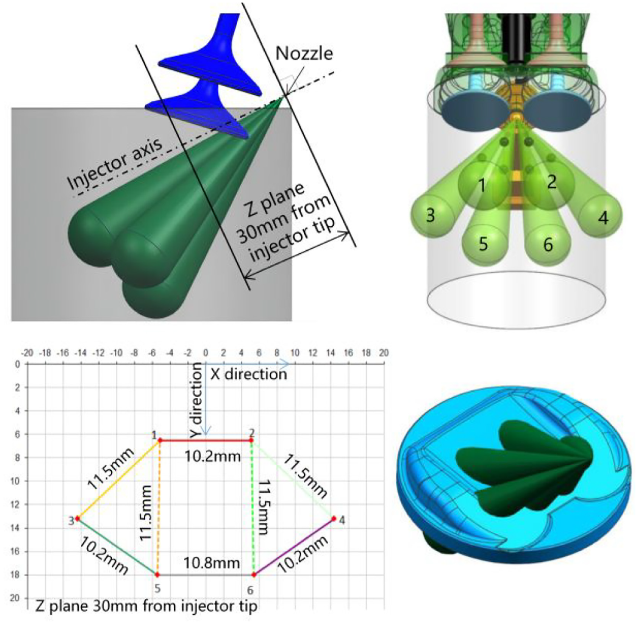
Sprayed oil droplet distribution.
A computational fluid dynamics (CFD) analysis was performed on the engine when rotating at 6000 r/min and working under rated operating conditions (Figure 11). During the intake stroke, at a 460° CA, the transient tumble ratio reached peak value A, mainly because of the intake flow and the masking design of the intake valve. As the piston continued to descend, the valve lift increased considerably, the intake air flow also increased, and the tumble ratio decreased. During the compression stroke, the piston rose and the tumble ratio increased, reaching peak value B at the crankshaft angle of 650° CA. The correlation between the turbulent flow intensity and the tumble ratio was very strong, which caused the tumble flow to be crushed and partially transformed into turbulent flow. At the crankshaft rotation angle of 690° CA, the turbulent flow intensity then reached peak value C. Subsequently, the turbulence intensity began to decrease. At the crankshaft rotation angle of 714° CA, a high and uniform turbulence was formed at the center of the spark plug electrode, and the turbulence intensity could reach 0.75, and would ensure stable combustion and a rapid early flame spread.

CFD analysis of the rapid combustion model.
A flow box was installed on the test bench and a light sheet was installed on the test plane at a distance of 0.5 D (where D is the cylinder diameter) from the bottom surface of the flow box (Figure 12). Using particle image velocimetry (PIV), a mass flow test device, a data processor, a camera and other equipment, the rapid combustion model of the DHE16GDI engine and the intake port of the DAM16N engine were tested for stable flow under different valve lift conditions. 13 Using the experimental data and the boundary parameters, the flow coefficient and the tumble ratio were then calculated under the different valve lift conditions, with results as shown in Figure 13. The DHE16GDI engine was then compared with the DAM16N engine; when the valve lift was low, the tumble ratio of the former was as high as 3.94, which mainly resulted from the valve masking design, and the flow coefficient did not change substantially. When the valve lift was greater than 6, the tumble ratio of the DHE16GDI engine was higher than that of the DAM16N engine by 1–1.2. The flow coefficient of the DHE16GDI engine decreased, however, with a maximum reduction of 3.6%.

Flow test method and test equipment.

Flow coefficient and roll ratio under various valve lift conditions.
The fast combustion model can increase both the tumble ratio and the turbulence intensity, improve the early flame propagation speed, and also ensure combustion stability. When used in combination with high EGR rates and lean burn techniques, a performance boost is achieved, mainly because the presence of exhaust gas from the EGR or lean air in the combustion chamber slows down the combustion process.
Matching of cooled EGR and lean burn
Lean burn can promote complete combustion of the fuel through input of excess air and thus improves the thermal efficiency of the gasoline direct injection (GDI) engine; however, the mole volume fraction of the oxygen in the mixture does not change. Large quantities of residual oxygen enter the exhaust gas after combustion and this inhibits NOx purification through a three-way catalytic converter, thus resulting in high costs for NOx emission control. Cooled EGR introduces numerous triatomic molecules, e.g., CO2 and H2O, into the exhaust gas content in the intake air, which dilutes the oxygen content in the mixture and increases the mixture’s specific heat capacity; this reduces the maximum combustion temperature in the cylinder, the heat transfer loss and the NOx emissions, suppresses knocking, and improves the engine’s thermal efficiency. However, the effect is not as good as that of lean burn. 14 Therefore, the effects of the synergistic matching scheme for these two technologies on the engine’s thermal efficiency and NOx emissions must be studied.
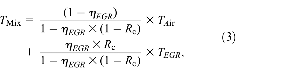
Air is a mixture of gases, where O2 accounts for 20.95% of the volume and N2 accounts for 79.05% of the volume (for the convenience of calculation, the volumes of other gases, e.g. argon, are incorporated in the volume of N2); therefore, the volume ratio of N2 to O2 in air is 3.773. The chemical reaction equation for complete combustion of gasoline can be expressed as follows:
where λ is the excess air coefficient. According to equation (2), when the fuel is burned completely, the total gas that remains constitutes N2, O2, CO2 and H2O.
The variation law of the intake air mixture volume fraction with the EGR rate (ηEGR) and the air–fuel (A/F) ratio was studied (Figure 14). Under the same A/F ratio conditions, when ηEGR increases, the volume fractions of CO2 and H2O increase, while those of N2 and O2 decrease. For example, when the A/F ratio is 15, the EGR rate increases from 0% to 25%, the CO2 volume fraction increases from 0% to 3.12%, the H2O fraction increases from 0% to 3.51%, the O2 fraction decreases from 20.95% to 15.71%, and the N2 fraction decreases from 79.05% to 77.66% (black circle). Under the same ηEGR (where ηEGR is not equal to zero) conditions with increasing A/F ratio, the volume fractions of CO2 and H2O both decrease, while those of N2 and O2 increase. For example, when the EGR rate is 20, the A/F ratio increases from 15 to 30, the CO2 fraction decreases from 2.49% to 1.29%, the H2O fraction decreases from 2.81% to 1.45%, the O2 fraction increases from 16.76% to 18.78%, and the N2 fraction increases from 77.94% to 78.43% (purple line). These results showed that the EGR rate and the A/F ratio have opposite effects on the volume fractions of the mixture components. If the two parameters are reasonably well matched, then the optimal combustion mixture can be realized.

Variations of the volume fractions of the mixture with ηEGR and the A/F ratio.
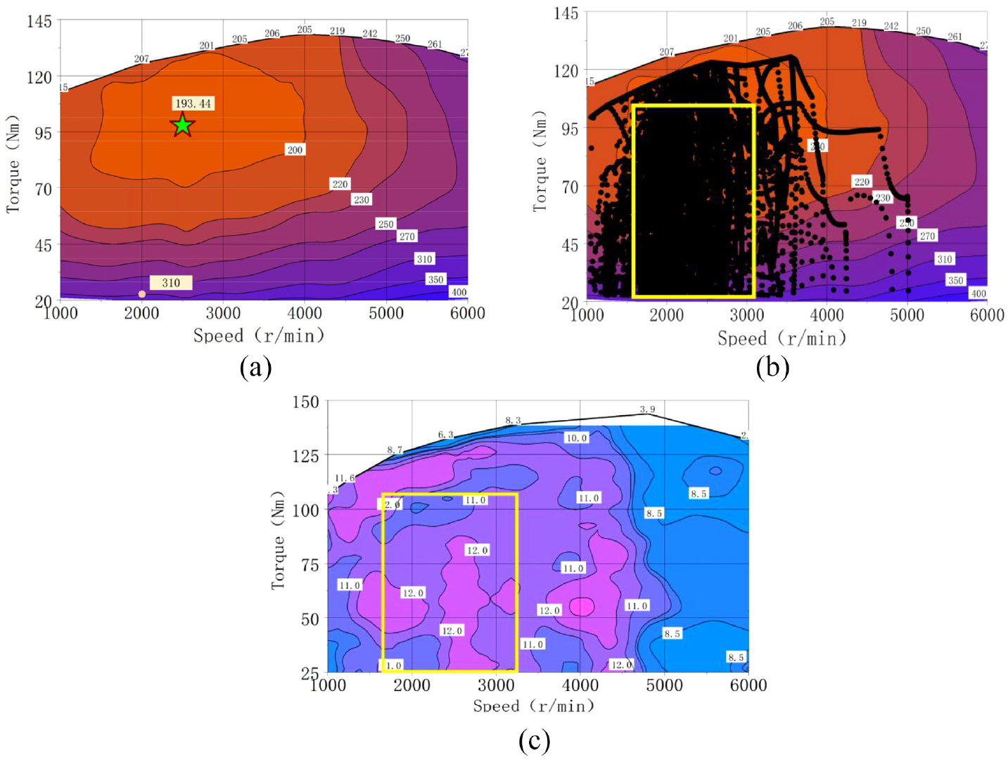
To study the effects of the temperature of the exhaust gas for EGR on the air mixture in the intake system, the ambient temperature is assumed to be 40°C, the ambient humidity is considered to be 50%, the intake pressure is 1 bar and the air and the exhaust gas are mixed adiabatically. The temperature (TMix) of the mixture in the intake manifold is given as follows:
where the ηEGR value is selected to be from 0% to 25%; Rc is the heat capacity ratio, where Rc = Cp.EGR/CP.Air (Cp.EGR is the constant pressure specific heat capacity of the EGR gas and CP.Air is the constant pressure specific heat capacity of air) and its value is calculated using the data from the “Handbook of Thermophysical Properties of Materials Commonly Used in Engineering” and the volume fractions of the mixed gas components. 15 Additionally, TAir is the air temperature and TEGR is the EGR temperature.
TMix increases with increases in ηEGR and TEGR, which results in a reduction in the charge efficiency and an increase in the fuel consumption (see Figure 15). To minimize the effective fuel consumption, TMix must be cooled to a near-ambient temperature (approximately 50°C), 16 but the exhaust gas contains considerable water vapor and a condensation risk exists because of the influence of the ambient humidity. When TEGR is 50°C and ηEGR is within 10%, zero condensation occurs in the intake manifold. When TEGR is ≥80°C, the gas inside the intake manifold presents no risk of condensation at each ηEGR. In addition, the EGR coolant is usually taken from the engine coolant and its temperature usually ranges from 85°C to 95°C. Therefore, controlling TEGR to be within the 50 to 100°C range can eliminate the condensation risk.

Variations in the mixture temperature with TEGR and ηEGR in the intake system.
When TEGR is 80°C, the equation for the adiabatic compression unburned gas temperature (Tunburned_TDC) can be given as follows:

where PTDC is the gas pressure in the cylinder at the end of the compression process, and κ is the adiabatic index. The results showed that Tunburned_TDC decreases with increasing ηEGR (Figure 16). In particular, when ηEGR is 25%, low temperature combustion is achieved; this combustion occurs at a temperature that is 18.5°C lower than that when ηEGR is 0% and is beneficial in reducing both knocking and NOx emissions.

Tunburned_TDC for different values of ηEGR versus the O2 mole fraction.
A clean cooled EGR system was designed as part of this work (Figure 17). The exhaust gas for this system is drawn from the downstream part of the three-way catalytic converter, and after the gas is cooled using the EGR cooler, it enters the intake manifold through the EGR valve and is mixed with fresh air.

Cooled EGR system design.
To use the advantages of cooled EGR and lean burn to provide low fuel consumption, low NOx emissions and low knocking, calibration experiments were performed with various values of the A/F ratio and ηEGR (Figure 18). The following experimental conditions were used: the engine speed was 2500 r/min, the brake mean effective pressure (BMEP) was 8 bar, the A/F ratio ranged from 15 to 25 and ηEGR ranged from 10% to 25%. The experimental method involved a gradual increase in the A/F ratio from 15 to 25; the increment step was 1, and at each A/F ratio value, the sweep point calibration was performed by increasing the EGR content from 10% to 25%. To compare knocking trends, the maximum cylinder pressure timing (i.e., the timing at which the cylinder pressure peaks) was used. When the engine was run at the minimum advance for best torque (MBT), the maximum cylinder pressure timing occurred at 10° to 15° after top dead center (ATDC); when the maximum cylinder pressure timing started to retard, knocking began to occur.

Effects of combination of lean burn with cooled EGR.
The effects of cooled EGR and lean burn on knocking were then analyzed. When the A/F ratio remains unchanged, ηEGR increases, the timing of the maximum cylinder pressure decreases, and knocking is then alleviated. This phenomenon occurs mainly because of the change in the volume fraction of the mixture components that occurs in the intake pipe, which affects the chemical reaction. However, an increase in the intake air volume reduces the combustion temperature of the mixture along with the heat exchange with the wall surface and the wall temperature. In terms of reducing knocking, lean burn has less of an effect than cooled EGR, mainly because lean burn cannot change the content of each mixture component and thus can only reduce the combustion temperature by increasing the amount of air at the intake, which reduces knocking.
Following analysis of the effects of lean burn and cooled EGR on NOx emissions, ηEGR and the A/F ratio can be used independently to reduce NOx emissions and keep them at a low level. For example, when ηEGR is 25% and the A/F ratio is ≥19, the NOx emission reaches its lowest value; in addition, when ηEGR is 20% and the A/F ratio is ≥20, the NOx emission can also reach this lowest value.
The comparison analysis of the thermal efficiency shows that when the A/F ratio is >17, the curve with the ηEGR value of 20% shows the highest thermal efficiency, with a value that increases with increasing A/F ratio.
The matching study of cooled EGR and lean burn showed that when the A/F ratio is 20 and ηEGR is 20%, the comprehensive effect on reducing knocking, reducing NOx emissions and improving the thermal efficiency and the fuel combustion duration is at the optimal level, and the maximum thermal efficiency can reach up to 44%.
Uniform cooling system
Four cooling system circulation modes were designed (Figure 19). When the engine starts (Figure 19(a)), the electronic water pump turns off, the coolant does not flow and the heat generated by combustion heats the engine body to achieve rapid warm-up and reduce heat transfer loss. When the engine is in the warm-up stage (Figure 19(b)), the double thermostat is closed, the electronic water pump is opened and the EGR cooler is connected in series with the heater. After the coolant is heated by the combustion chamber, part of the coolant then enters the EGR cooler for further heating. The coolant subsequently enters the heater to accelerate warm air preheating and improve passenger comfort in the cockpit. Part of the coolant also flows into the oil cooler to heat the oil and improve the waste heat utilization rate. When the engine enters the cooling stage (Figure 19(c)), the body is heated completely, the electronic water pump and the main thermostat are turned on, and heat is dissipated to the exterior in line with the requirements of the engine’s working conditions. When the engine is under extreme driving conditions, e.g., a heavy load (Figure 19(d)), the electronic water pump and the dual thermostats are opened completely, thus allowing a large quantity of coolant to flow through the combustion chamber to ensure both the thermal load and the reliability of the engine.

Cooling system circulation structure.
The main thermostat is an electronic thermostat that can control the coolant to function at different temperatures (Figure 20). When the engine is in the low-speed, medium-low load area, the coolant temperature is controlled at 105°C to achieve the minimum friction and minimum heat dissipation loss. When the engine is operating at high speed with a high load, the coolant temperature is controlled at 90°C to avoid abnormal knocking and ignition. The cylinder thermostat controls the coolant temperature to within the 100 to 105°C range, which can reduce oil viscosity and the friction losses of the moving parts.

Coolant temperature control strategy.
A thermal analysis was performed on the engine at the rated speed and under the rated operating conditions (Figure 21). This analysis can be divided into three heat-loading cycles. The first cycle starts from room temperature and the cycle time is determined based on the complete stabilization of the temperature in the nose bridge area on the exhaust side of the cylinder head. On the exhaust side of the combustion chamber in the cylinder head, the maximum temperature change rate for each cylinder nose bridge area is <3% and the maximum temperature is 236°C. On the side wall of the cylinder shoulder, the maximum temperature change rate is 2.1% and the maximum temperature is 193°C. The wall temperature of the combustion chamber is uniform and is maintained at a high level, which is beneficial in reducing heat and friction losses.

Heat transfer analysis of the DHE16GDI engine.
Based on the characteristics of the DAM16N engine, when the maximum power speed is 6000 r/min, the maximum torque speed is 4400 r/min, the speed for minimum fuel consumption is 2400 r/min and the defrosting speed is 1200 r/min, when the coolant temperatures are 105°C, 95°C and 85°C, respectively. An engine fuel consumption test was also performed (Figure 22). When the engine operates at a low torque of 60 Nm and a low-medium speed of 2400 r/min, the engine with the coolant temperature of 105°C shows the lowest fuel consumption, which is 3 g/kWh lower than the fuel consumption of the engine with the coolant temperature of 95°C, and its thermal efficiency is higher by approximately 0.5%. When the engine operates at a high torque of 100 Nm and high speeds of 4400 r/min or more, the fuel consumption of the engine with the coolant temperature of 95°C then offers an advantage.

Comparison of fuel consumption at different coolant operating temperatures under characteristic operating conditions.
Engine performance test
On the test bench, the performances of the DHE16GDI and DAM16N engines were tested.
The maximum power and torque of the DHE16GDI engine are 80.52 kW and 138.58 Nm, respectively, and the torque fluctuation (representing the rate of change of the maximum torque at the current speed relative to the torque at the previous speed) reaches a maximum of 2.9% (Figure 23). When compared with the DAM16N engine, the maximum power is reduced by 4.18%, the maximum torque is reduced by 5.12% and the torque fluctuation is reduced by a maximum of 36.6%; this can reduce the power loss and improve the engine’s operating efficiency.

Engine performance test results.
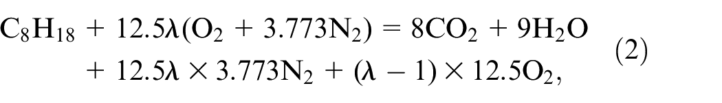
The new DHE16GDI engine achieved excellent fuel consumption results (Figure 24(a)). The lowest fuel consumption rate was 193.44 g/kWh, the characteristic point fuel consumption rate at 2000 r/min and 2 bar was 310 g/kWh, and the highest thermal efficiency was 43.9%; when compared with the DAM16N engine, the thermal efficiency of the DHE16GDI engine is improved by approximately 4.4%.
DHE16GDI and DAM16N engine fuel economy comparison.
The torque points of the DAM16N engine (matching the F101 car) when operating under the conditions of the Worldwide harmonized Light-duty vehicles Test Cycle (WLTC) were coupled to the fuel consumption characteristics of the DHE16GDI engines (Figure 24(b)). The analysis shows that the torque point of the engine running in the area from 1700 to 3200 r/min and 25 to 105 Nm accounts for approximately 69.8% of the total operating torque point, which is the common working condition area of the vehicle.
The fuel consumption characteristics of the DAM16N engine and the DHE16GDI engine were coupled together (Figure 24(c)). The comparison shows that when compared with the DAM16N, the fuel consumption of the DHE16GDI engine in the area shown in Figure 24(b) is lower by more than 11%.
The fuel consumption characteristics show that, when compared with the DAM16N engine, the main pollutants, i.e., NOx, CO and the total hydrocarbon content (THC), of the DHE16GDI engine were reduced by 43.1%, 34.8% and 8.3%, respectively (Figure 25). This improvement is mainly due to the use of rapid combustion and intelligent cooling technology, which allows the engine to operate rapidly and reasonably efficiently at start-up and under low revs, suppressing both CO and hydrocarbon production. Under medium and high loads, the lean burn and cooled EGR can be matched reasonably well, which reduces the combustion temperature and the oxygen content and also suppresses NOx generation.

Comparisons of major pollutant discharge characteristics.
Conclusions
Based on the DAM16N engine, technologies to enable reduced fuel consumption and increased thermal efficiency are studied and applied to the development of the DHE16GDI engine. The main conclusions drawn from this work are given as follows.
A rapid combustion model with a high CR and high tumble flow was developed through appropriate structural design of the intake port and the combustion chamber and by using a reasonable arrangement of the spark plugs and injectors. When the valve lift was >6, the tumble ratio increased by 1 to 1.2, but the flow coefficient decreased with a maximum reduction of 3.6%.
For synergistic matching of the lean burn and cooled EGR technologies, and when using the combination of an engine speed of 2500 r/min, a BMEP of 8 bar and an A/F ratio of 20, an ηEGR value of 20% has the optimum matching effect and can suppress knocking and reduce NOx production effectively.
By optimizing the cooling system structure and performing an integrated design of the dual thermostat, the electronic water pumps and other system technologies, the wall temperature of the combustion chamber for each cylinder can be made uniform with a maximum temperature change rate of <3%. When the engine runs within a maximum speed of 2400 r/min and torque of 60 Nm, the coolant is at a high temperature, reaching up to 105°C; this reduces both heat dissipation and friction losses and increases the maximum thermal efficiency by 0.5%.
A performance comparison experiment was also performed. When compared with the M16N engine, the DHE16GDI engine output maximum power of 80 kW and a maximum torque of 138 Nm with small torque fluctuations and stable operating conditions. The fuel consumption was reduced by >11% under medium-low speed and medium-low load conditions; the minimum fuel consumption rate was 193.44 g/kWh and the maximum thermal efficiency reached 43.9%, representing an increase of more than 4.4%. The main pollutants, comprising NOx, CO and the THC, were reduced by 43.1%, 34.8% and 8.3%, respectively.
Theoretical and bench tests confirmed the effectiveness of the rapid combustion technology, the lean burn approach and cooled EGR technology in improving engine thermal efficiency, suppressing knocking and reducing NOx emissions. Although further vehicle verification will be required, it is believed that the combination of technologies presented in this study will provide an effective method to improve fuel economy in the future.
Footnotes
Appendix
Acknowledgements
This project was strongly supported by the Extended Range Power System Research Institute, and we also thank Dongan Automotive Power Co., Ltd.
Handling Editor: Chenhui Liang
Declaration of conflicting interests
The authors declared no potential conflicts of interest with respect to the research, authorship, and/or publication of this article.
Funding
The publication of this article was financially supported by Harbin Dongan Automobile Power Co., Ltd. and Heilongjiang Province’s “Hundreds, Thousands, and Tens of Thousands” Engineering Science and Technology Major Projects (project fund: SC2021ZX05A0013).