
Abstract
Gearbox is a widely used component in mechanical transmission and plays a vital role in the operation of locomotive. With the development of aluminum alloy materials and molding technology, the monolithic casting gearbox has a widely application prospect. This paper focuses on the manufacturing method of Selective Laser Melting processing for high strength aluminum alloy locomotive traction gearbox. Firstly, the influence factors of laser melting process on the placement angle, support type and support spacing are studied through orthogonal experimental design. It is found that the placement angle has the greatest impact on the forming accuracy, the support spacing takes the second place, and the support type has the least impact on the forming accuracy. When the placement angle is 45°, the support spacing is 1 mm, the steel wire support is added to the support type, which has the least impact on the forming accuracy. Then, the processing ability of the whole box structure is verified by using the Fused Deposition Modeling technology. With using the optimized optimal parameter combination, it can be found that the volume of the printing box is 100 cm3, the mass is 280 g, the surface roughness is 6 μm, and the precision is 0.15 mm. Then the laser melting forming process is carried out in the selected box area. Through experimental analysis, a prototype is developed. At the same time, the process parameters of selective laser melting forming for the whole box structure can be obtained.
Keywords
Introduction
With the advancement of science and technology, locomotives are developing in the direction of high speed, heavy load and lightweight. The safety and reliability of their operation must be taken seriously. Among the various components of the locomotive, the most critical component is the drive system, which is mainly composed of traction motor, gearbox assembly, and hollow shaft assembly.
The structure of the drive system is shown in Figure 1. The structure drive system of the gearbox, including the shaft, cage, gearbox, flywheel, engine and other components. The most core component in the figure is the gear. The gearbox indirectly controls the running speed of the locomotive through the gear transmission, and also plays a key role in carrying the torque. As a key part of the locomotive, the drive system is mainly used to achieve the adjustment of the locomotive running speed and load-bearing torque.

The composition of the drive system.
From the perspective of forming technology, there are two main types of manufacturing methods of gearboxes which are welding and casting. Among them, the welding process has a large workload on the gearbox, and the processing cycle is relatively long. However, the machining process of the casting gearbox is relatively small, and the processing cost is relatively low. The split casting box is made up of the upper box and the basic case that is combined with bolts. It is easy to assemble gears, shafts, bearings and boxes in use, so it is widely used in various types of locomotives. 1
Since there are some difficulties in the processing and assembly of the split box, it is considered to cast the shaft hole completely in one part, so the requirements for the integrity of the box are put forward, that is, the two parts of the upper and lower box are designed as one box, so as to ensure the integrity of the shaft hole, reduce the assembly error and reduce the probability of transmission shaft failure.
Integration refers to making all functions jointly use the resources within the system, so as to reduce the total number of equipment on the platform, reduce the interference between each other and improve the reliability of the system. Considering the advantages and disadvantages of the split box, the integrated box structure shown in Figure 2 is obtained. Therefore, the integrated design of the gearbox will be based on the integrated box, that is, on the premise of considering the system relationship between multiple parts, reduce the processing cycle and reduce the complexity of the processing process as much as possible, At the same time, the principles of assembly, stress and fatigue reliability are put forward for the integrated design of locomotive traction gearbox,2–4 so as to improve the overall reliability of gearbox.

Structure of holistic box.
In the integrated design of the gearbox, the suspension mode on the bogie shall be considered, so the suspender device shall be added to the gearbox; In addition, according to the stress condition of the box, the stiffener plate shall be added at the position with large stress in the structure to improve the overall strength of the box. In addition, due to the large volume of the box, it is impossible to use manual handling in the handling process, so lifting earrings are added on the box to facilitate the hoisting and installation of the gearbox by machine. To sum up, the front structure of the box is shown in Figure 3(a).

Structure of integrated gearbox: (a) front structure of box and (b) box motor side structure.
In addition to the above considerations, attention should also be paid to the relationship between the box, the axle box and the motor. 5 Therefore, the structure of the integrated box should be adjusted. Since the gear is installed from the front of the box, the motor side opening of the box does not need to be too large and can be assembled with the motor shaft and axle. Therefore, the motor side structure of the box after adjustment is shown in Figure 3(b).
The service environment of the integrated box determines two stress conditions, namely, operation condition and overload condition, and the overload condition is divided into vibration impact condition and motor short circuit condition. 6 According to the concept of integrated design, comprehensively considering the relationship between various parts in the gearbox system, through the principles of assembly, stress condition, 7 fatigue reliability, etc, The integrated box is designed. On this basis, the performance of lubrication, safety, oil collection and sealing are fully considered. Finally, the integrated box composed of box, large box cover, small box cover, oil collection groove, bolts, gaskets, and other parts is obtained8,9 as shown in Figure 3. Figure 3 is the three-dimensional model of the integrated box designed after following the integrated design rules, in which the dark green is the gear box cover, and the overall gear box becomes a whole according to the integrated design principle.
This paper mainly studies the forming technology of locomotive traction gearbox. The basic process of narrowing and printing the box using the laser melting technology of the selection area is studied. The orthogonal test is used to verify the influence of the placement angle, support type and support spacing on the forming precision during the laser melting technology. The processability of the integrated box structure is verified by plastic printing. Then, the reduced integrated gearbox is printed using the Concept Laser M2 device according to the best parameters obtained.
Model inclination orthogonal test
According to the maximum size that can be formed by the device of CL M2. And the integrated gearbox case is processed, which the size is reduced by 10 times.
Process parameter optimization
This paper intends to verify the influence of various parameters on the forming precision during the laser melting process of the selected area by orthogonal experiment. 10 The effects of laser power, layer thickness, and scanning speed on forming accuracy were studied. The orthogonal experiment has been designed on the placement angle of the parts, the type of support, and the gap of the supports to achieve the purpose of parameters optimization. 11 Due to the large size and irregular structure of the box, the forming process is difficult. Therefore, in the orthogonal experiment, according to the shape proportion of the box, a thin-walled rectangular parallelepiped model is established. The model is shown in Figure 4.

Cuboid model.
Placement angle
The placement angle of the part mainly depends on the molding efficiency of the 3D printing technology. As shown in Figure 5(a), if the part is placed vertically, the length in the y-direction is 20 mm. Its size is relatively larger, so the time required for processing is increased, and the molding efficiency is low. As shown in Figure 5(b), if the parts are placed horizontally, more support needs to be added. And the support penetrates the pores inside gearbox case. Inside support is difficult to remove and affects the surface quality of the molded body. As shown in Figure 5(c), it can reduce the amount of support and the size of Y direction when the parts are placed obliquely. In particular, the support in the gearbox is reduced, and the placement angle of the parts is up to 15°. At 30° and 45°, the forming precision will change.

Diagram of parts placed on printing platform: (a) the parts are placed vertically, (b) horizontal placement of parts, and (c) the part is placed obliquely.
Support type and gap
The types of support are generally divided into three types: point-support, line-support, and surface-support. Therefore, considering the addition of point-support, line-support, and surface-support to the part, the molding accuracy of the part will change.
At the same time, the size of the inner gap of support also has a certain influence on the precision of the mold itself. When the support is added too densely, the powder is wasted. If the added support is too sparse, it may cause the widget to collapse and cannot be printed successfully. Therefore, it is necessary to select a suitable support type and spacing. According to the size of the machined part, the proper support pitch is selected. Due to the small size of the processed rectangular parallelepiped, the variation of the forming precision is considered when the support spacing is 0.5, 1, and 2 mm respectively. Figure 5 is a schematic diagram of placing the box at different angles, simulating different angles respectively. And the different orthogonal design level factor is shown in Table 1.
Orthogonal design level factor table.
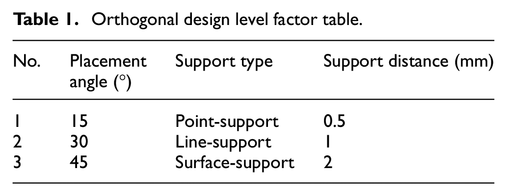
The effects of part placement angle, support type and support spacing on forming accuracy are considered. 12 Using orthogonal experiment to select a representative sample from 27 test samples not only reduces the number of tests, but also obtains more accurate results. The horizontal coefficient of orthogonal test is shown in Table 5. The point support is a conical structure. The contact diameter between the part and the structure is 1 mm and the contact diameter with the base plate is 2 mm.
Place nine boxes on a plane and process them once. Save the cuboid model in STL format and import it into Materialize Magics software. As shown in Figure 6, the placement angle, support type, and support spacing of the part is placed according to the designed orthogonal table.

Pre-processing of parts: (a) placement angle setting and (b) support addition.
After adding the support, the parts are layered and divided into 464 layers with a layer thickness of 50 μm. The layered file is imported into the 3D printer for laser melting technology. After 2 h 50 min, the parts are processed, as shown in Figure 7. Figure 7 is the physical arrangement diagram of the comparative experiment by printing the samples according to different placement angles and types and placing them on the plane. The sample was heat-treated, and each part was marked after the heat treatment, number from 1 to 9.
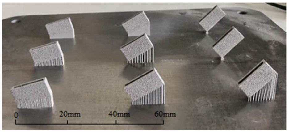
Printing samples.
Orthogonal test data processing
The purpose of the orthogonal experiment design is to obtain the parameter combination with high forming precision. The forming precision of the part is mainly used as the evaluation index, which is closely related to the error. Therefore, the length of the nine molded bodies is respectively determined by the vernier caliper. The width, height, and thickness of the four sides were measured, and the thickness was taken as the average of the thickness of the four sides. The measurement results are shown in Table 2.
Results of side length.
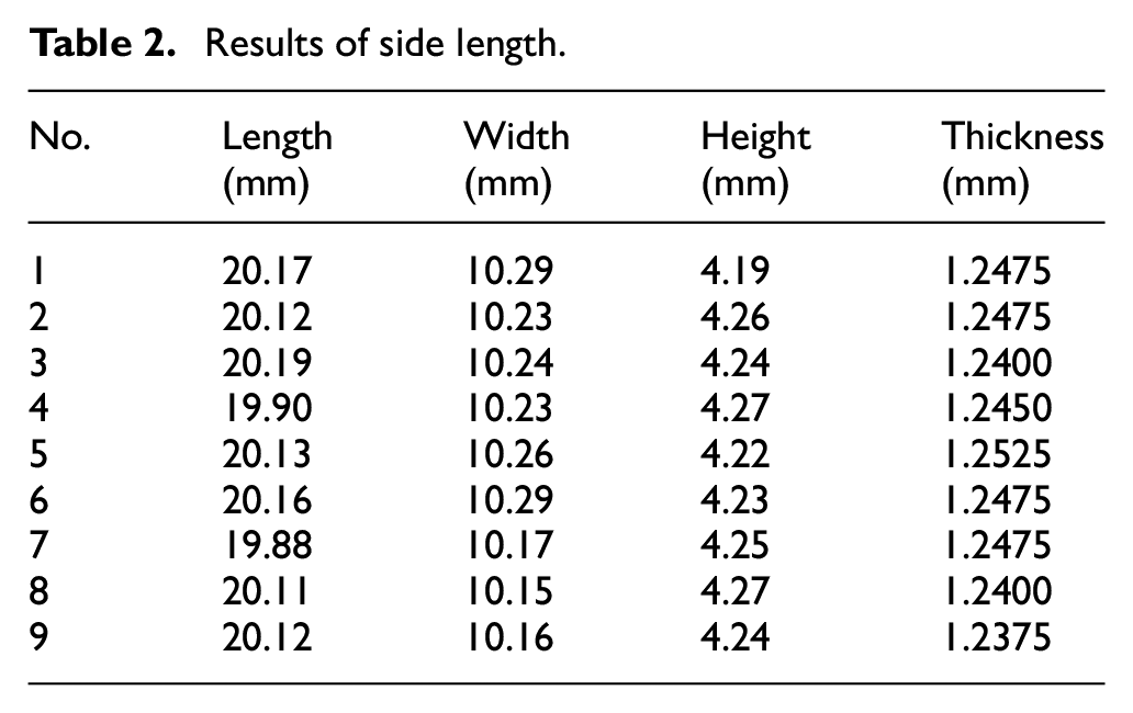
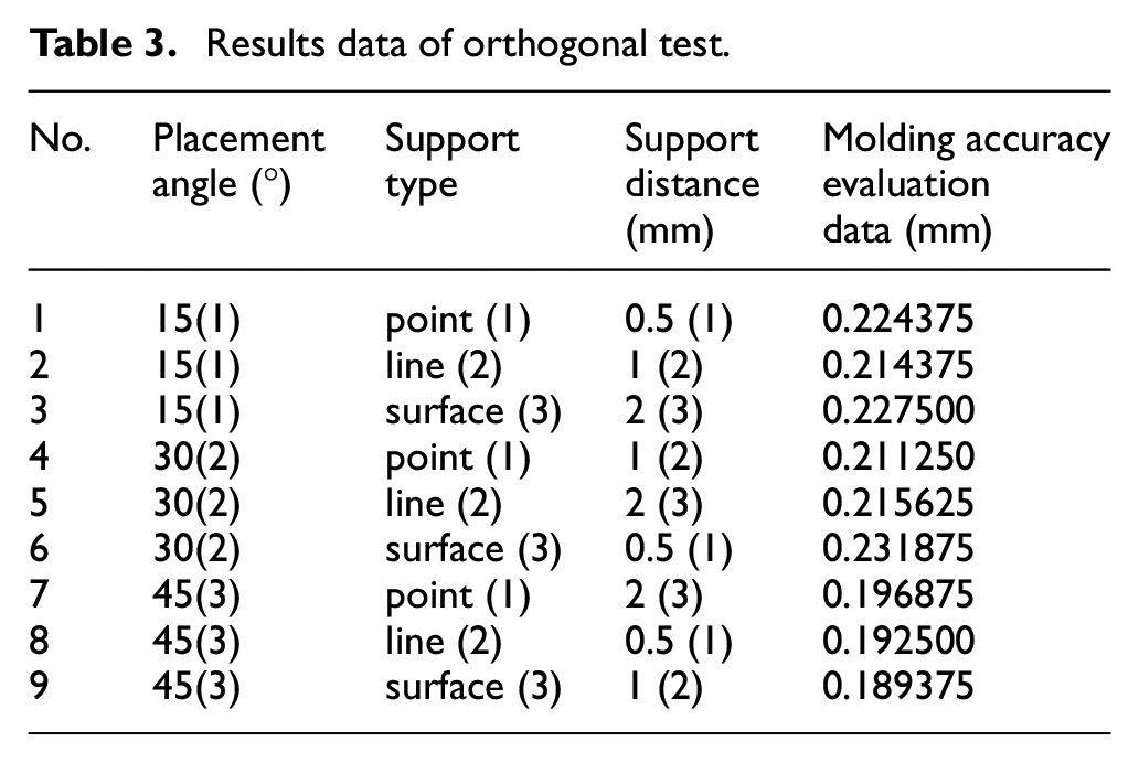
Take the average of the actual value of each side length which are shown in Table 2. The length of each side is represented by the cube of modeling time, which is the error value of the whole part. At the same time, this error value is used to measure the precision of modeling. In summary, the orthogonal experiment’s results obtained by calculation are shown in Table 3. The smaller the error is, the higher the precision is.
Results data of orthogonal test.
According to the above orthogonal experiment’s results, the data were processed by visual analysis and variance analysis. Conclusion can be drawn directly by the method of direct analysis. The primary and secondary effects of various factors on the forming precision of machined parts are sorted according to the size of the range. Therefore, intuitive analysis method is also known as range analysis method.
Among them, the formula for the range is:

Where,
M represents a factor, N represents a level, m represents the number of factors, and n represents the number of levels.
The available factors are calculated by the formula (1) with the data from Table 3. The intuitive analysis method results as shown in Table 4.
Intuitive results of samples.

It can be seen from the data calculated in Table 4 that the sequence of the range factor is: R(A) > R(C) > R(B). That is to say, the placement angle has the greatest influence on the forming precision, and the support spacing takes the second place. Relatively speaking, the support type has the least influence on the forming precision. Therefore, the placement angle should be considered when choosing the laser melting forming of parts. The selection of placement angle has a great influence on the forming precision of parts.
If the forming precision is more precise, the horizontal mean value of influencing factors should be selected as the lowest combination, and its position is (3, 2, 2). This means that the part needs to be tilted by 45° and a line bracket with a spacing of 1 mm is added to obtain the part with the best precision. The variance analysis method can make up for this shortcoming, and the result is more accurate. After calculation, the results of the variance analysis data can be obtained, as shown in Table 5.
Variance analysis results of samples.

According to the data obtained by the variance analysis method of Table 5. In the selected laser melting process, the placement angle of the part has the greatest influence on the forming precision among the three factors: the placement angle of the part, the support type, and the support spacing. The second is the support spacing, and the least affected is the support type.
According to the results of comprehensive visual analysis and analysis of variance. In the process of laser melting forming in the selected region, the most important factor affecting the forming precision is the placement angle of the part. And the 45° tilting placement is the best informing precision. The spacing of the support should not be too small. Otherwise, it is not easy to remove, and it will affect the forming precision. For the established rectangular model size, the best support spacing is 1 mm. The influence of support form is the least, and the part with steel wire support is added. Since the F-ratio of the support spacing and the support type is small, it is proved that they have little influence on the forming precision. It can be analyzed according to the specific structure and size.
Selection laser melting processing gearbox
The casing is processed by selective laser welding technology. Processing is divided into three parts: data processing stage, processing stage, and post-processing stage.
Plastic model 3D printing test
Due to the lightweight requirements of the integrated box, the aluminum alloy material with less density is mainly selected in the material selection. 13 The aluminum alloy material that can be used for rapid prototyping is mainly AlSi10Mg, and its morphology is shown in Figure 8. Figure 8 is the micro morphology of the selected AlSi10Mg material. Its range is 15–53 μm. AlSi10Mg is suitable for rapid prototyping due to its good air tightness, excellent mechanical properties, physical properties, and corrosion resistance technology. 14 AlSi10Mg can bear large load and good mechanical properties. According to the morphology, particle size, chemical composition, and mechanical properties of AlSi10Mg, the material is suitable for processing thin-walled parts such as box. Therefore, AlSi10Mg is formed into an integrated box by laser selective melting technology. 15
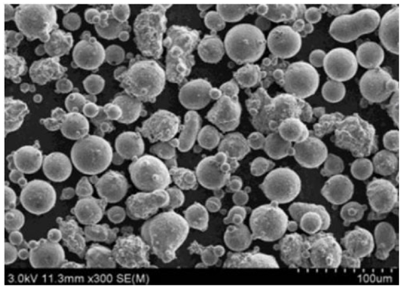
Morphology of AlSi10Mg.
From the point of view of machinability, the overall box structure should be properly adjusted, such as round hole chamfering. Whether the renovated box structure can be processed by 3D printing technology needs a certain verification process. 16 Due to the high cost of metal printing, the structure of the integrated box is verified by the relatively low-cost plastic printing technology. This paper uses a ZORTRAX M200 plastic printer to print with ABS material.
Base on the orthogonal experiment’s results, the STL format of the integrated box is imported into the Z-SUITE software. At the same time, the space position is placed on the platform at 45°. Then, the support is added, as shown in Figure 9.

Plastic printing integrated box support added.
The support of the box is mostly on the outside. It’s very small inside, so it’s easy to disassemble and ensure the forming process of the box.
By observing the box structure after printing, it can be seen that the whole box sample obtained by printing plastic has good structure. It indirectly proves the printing feasibility of the whole box structure.
Layered processing
According to the orthogonal experiment, the optimization of the printing parameters is realized. Based on this, the rationality of the CAD model of the integrated box is verified by plastic printing. Therefore, the laser can be printed on the integrated box by the laser melting technology of the selection.
The integrated cabinet is placed at a tilt of 45° on the platform. The bottom cylinder is inclined 45° to the base plate to reduce the first contact area between the support and the part. So as to reduce the first contact stress and reduce the printing cost of each layer. In turn, this area reduces heat accumulation and thermal stress. The 45° placement also ensures that the angle of the oil return passage inside the plate box is above the limit angle. Thus, the roughness and accuracy of the oil return channel in the box are ensured. Finally, the lowest part of this part is set 2 mm away from the substrate to ensure the stability of printing.
The addition of support has an important influence on the shaping of the part. Although the laser melting technology of the selection area is similar to the plastic printing technology in principle. But it needs to consider more factors than plastic printing. Because of the high price of metal powder, in the process of adding support, not only the convenience of support removal should be considered, but also saving powder is an important factor. In the Materialize Magics software, support is added to the integrated box, as shown in Figure 10.
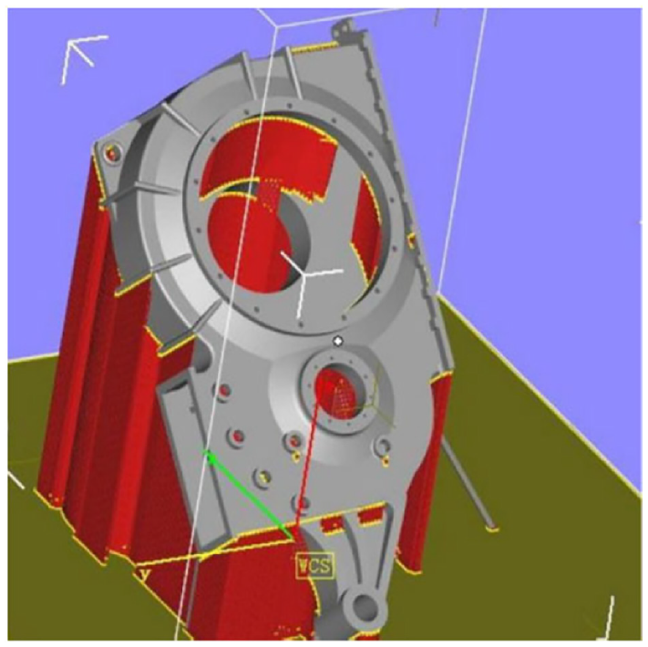
Adding support in Materialize Magics.
According to the size of the integrated gearbox, add automatic support. Then on this basis, artificial reinforcement is carried out. The “+” shaped support at the top is strengthened by adding new support at the suspension position. And add support on the round surface to ensure its roundness. Connecting the supports to prevent them being scraped off by the scraper. 17
After the support is added, the file is imported into the special layering software for layering, and the optimized slice thickness is optimized to 30 μm. Cut the 45° panel into 5000 layers. At the same time, fine laying and multi-layer printing ensure the precision and quality.
For CL-M2 equipment, the powder feeding amount, the powdering speed, the exposure sequence, etc. are all adjustable parameters of the equipment. It ensures the safety in the process of processing and the precision of processing samples. At the same time, the forming efficiency is further improved. The parameter settings are shown in Table 6.
Determined parameters of CL M2.

After the stratification is finished, the parameters in the processing of the laser melting equipment are also set in the software. Based on the experiment and the database, the optimized process parameters are adopted. And the support is formed with a faster speed to improve the forming efficiency. The specific parameters are shown in Table 7.
Printing parameters.

Selective laser melting
At present, the research on SLM technology is mainly concentrated in European and American countries, such as Germany, Belgium, the United Kingdom, the United States, etc. Such as MCP company in Germany, TRUMPF company in Germany and PHE-NIX company in the United States. Asia is mainly concentrated in Singapore, Japan and other countries, such as Japan’s Matsuura company and Japan’s Osakada laboratory. At present, the research on selective laser melting equipment mainly focuses on the type of laser, the spot size of the focusing surface, the powder spreading method and the powder spreading thickness of the piston cylinder. 18 Based on the advanced technology and equipment of American SCIAKY company, Xi’an BLT company has made in-depth research on the forming process, equipment, organization and performance control of parts, and has realized the manufacturing of titanium alloy, stainless steel, high-temperature alloy and other difficult to machine materials and parts with complex shapes. The German Institute of precious metals and metal chemistry FEM has found that mixing gold with iron and germanium can reduce the reflective rate of the alloy and significantly improve the quality of gold products printed by SLM. 19
After the cabinet structure is layered, the printing can be started by connecting the computer to the CL-M2 laser melting equipment. This process mainly realizes the processing of the parts. According to the above-mentioned stratification result of the box model, the laser melting is performed layer by layer. That is to say, the high-power laser action is used to melt and form a layer of metal powder laid on the bottom plate. The operating platform will move one layer of thickness, continue to lay down a layer of powder, and process. Then repeat the above steps, until the entire layer is processed. Finally, an integrated box model can be getting. 20
After a total of 33 h, the printing is completed. And the structure of the integrated box sample formed into the substrate is shown in Figure 11.

Forming diagram of integrated box.
According to the test standard GB/T3246.2, the formed AlSi10Mg was etched by Keller reagent. The density and microstructure of laser melted AlSi10Mg were observed by metallographic microscope. 21 The metallographic diagram of the formed body before corrosion and 100× magnification corrosion diagram is shown in Figure 12.
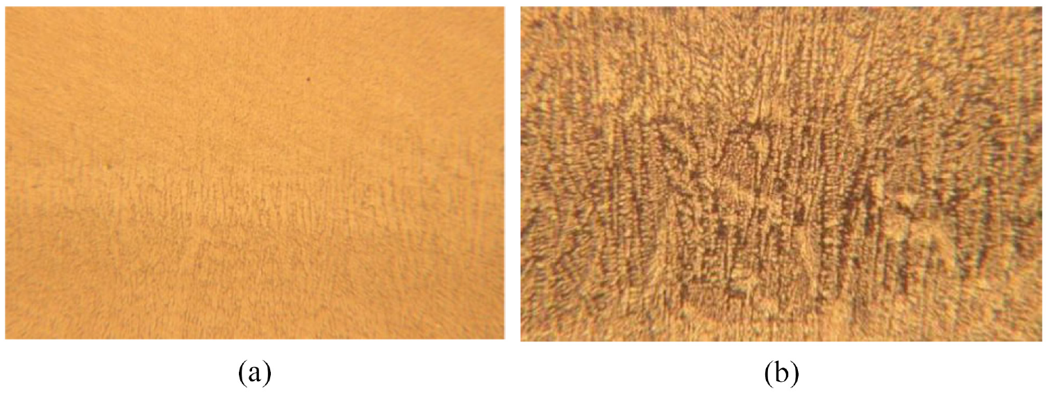
Metallographic chart comparison: (a) without corrosion and (b) 100× magnification corrosion diagram.
According to the metallographic diagram without corrosion, the AlSi10Mg sample is dense inside, with no obvious defects, high density, good molding quality. Through 100 times of metallographic observation, the reinforced phase Si can be obtained. The core region exhibits a refined dendritic morphology, while the enhanced phase Si in the laser remelting zone is slightly coarsened and exhibits a fractured, granular morphology. 22
Post-processing
After the processing is completed, the test piece is taken out and heat treated. The purpose of the heat treatment is to eliminate unnecessary stress generated during the internal processing of the test piece and prevent the warpage of the part. The general process of heat treatment is as shown in Figure 13. The temperature should rise heat to 240°C within 1.5 h. Then the temperature is kept for 6 h and cooled to room temperature.

Heat treatment process.
After having heat treatment, the test piece is placed in a wire-cutting machine. It is separated from the bottom plate, and the supports are removed. The next steps include grinding, polishing, sandblasting, etc. are performed to obtain an integrated box with good surface quality, as shown in Figure 14.

Metal printing integrated box structure: (a) front view structure and (b) reverse view structure.
The test piece has a volume of 100 cm3, a mass of 280 g, surface roughness of 6 μm, and an accuracy of 0.15 mm.
Conclusion
This paper mainly studies the forming and manufacturing technology of locomotive traction gearbox. In view of the difficulties of processing and assembling the split box, the forming and manufacturing design technology of integrated box is proposed. Firstly, the orthogonal experiments were conducted to verify the effects of placement angle, support type, and support spacing on the molded parts in the selective laser melting process. Through orthogonal test, it is concluded that the placement angle of the model has the greatest impact on the manufacturing process, and the highest accuracy is achieved when the placement angle is 45°.
At the same time, according to the best combination of parameters obtained from the orthogonal experiment, the volume of the printing box is 100 cm3, the mass is 280 g, the surface roughness is 6 μm, and the accuracy is 0.15 mm. Secondly, the 3D printing technology is applied to the new process forming technology of selective laser melting, and the plastic printing technology is used to verify the machinability of the integrated box structure. In this paper, the equivalent model method is used to optimize the forming and manufacturing process of locomotive gear box, and Concept Laser M2 device is used to reduce the printing of the box through the laser melting technology in the selected area. After the printing of the box is completed, the printed samples are post processed to obtain a higher quality integrated box.
Based on the original design technology of split type box body, this paper proposes an integrated design technology of forming and manufacturing for locomotive gearbox. The previous locomotive gear boxes used split type forming and manufacturing technology. The integrated manufacturing technology of locomotive gear box can reduce the difficulties of processing and assembly caused by split type forming and manufacturing, so as to enhance the reliability of the manufactured locomotive gear box.
At the same time, the 3D printing technology is applied to the new process of selective laser melting, and the gear box model in line with the assumption is printed through experiments.
Finally, the equivalent model method is innovatively used to optimize the forming and manufacturing process of locomotive gear box.
This paper puts forward a new structure of the integrated box for locomotive gear box processing, as well as a new method and process for the forming and manufacturing of locomotive gear box, which provides technical support for reducing the axle load of future locomotives. The new technology and process of locomotive gear box proposed in this paper can be used in the design, forming and manufacturing of small reducer, and also has certain applicability to the existing lightweight design, forming and manufacturing.
For the actual locomotive reducer, there is a lack of large-size and high-precision 3D printing and forming machine for overall printing, and it is unable to print high-precision and large-size gear boxes, which has certain limitations.
In the future, further experiments can be carried out on the forming equipment, and the forming and manufacturing process can be further optimized. Dynamic mechanical experiments can be carried out to verify the reliability of the new technologies and methods used.
Footnotes
Handling Editor: Chenhui Liang
Author contribution
All authors contributed to the study conception and design. Material preparation, data collection, and analysis was performed by [Liang Xuan], [Chunfei Zhang], and [Meichao Qin]. The first draft of the manuscript was written by [Liang Xuan] and [Chunfei Zhang], all authors commented on previous versions of the manuscript. All authors read and approved the final manuscript.
Declaration of conflicting interests
The author(s) declared no potential conflicts of interest with respect to the research, authorship, and/or publication of this article.
Funding
The author(s) disclosed receipt of the following financial support for the research, authorship, and/or publication of this article: This study was supported by State Key Laboratory of Precision Blasting, Jianghan University (No.PBSKL2022205), the China Railway Corporation Scientific Research Project (2017BX05) and Hubei Natural Science Foundation Project (No.2020CFB456). And appreciate the State Key Laboratory of precision blasting at Jianghan University which providing a comfortable research atmosphere for this research, also appreciate the Liaoning Provincial Key Laboratory of sports and rehabilitation equipment at Dalian Jiaotong University which providing us with support.