
Abstract
A coiled Helmholtz cavity acoustic metamaterial structure, which consists of three perforated plates, two channel layers and an air back cavity, is designed to address the problem of poor absorption of low-frequency band noise by conventional acoustic materials, and the results demonstrate that the absorption peak frequency of this structure is lower than that of a conventional Helmholtz cavity. The finite element method based on COMSOL multiphysics field coupling software is used to analyze the sound absorption characteristics of the metamaterial single-cell structure and to investigate the effect of structural parameter variations on its sound absorption performance. The problem of broadband sound absorption is solved by synergistically coupling two single-cell structures and then by designing the geometrical parameters of the coiled Helmholtz cavity structure, multiple basic units with absorption peaks at different frequencies are connected in parallel to design a multiunit coupled structure with low-frequency broadband sound absorption performance. In addition, the multiunit coupled structure is embedded in a porous material to design a composite space folding metamaterial structure, which can simultaneously absorb both low- and high-frequency noise and achieve a large broadband sound absorption performance above 200 Hz.
Keywords
Introduction
With the rapid development of the world’s shipping industry, ship transport traffic, and ship transport tonnage have been increasing year by year. Ship noise, especially low-frequency noise, has strong penetration and slow attenuation in water, and studies have found that noise pollution in the ocean affects marine animals to a greater extent than previously expected. 1 However, traditional noise-reducing acoustic materials for ships,2,3 such as foam and rock wool panels, need to be of a thickness comparable to the wavelength of the sound waves to achieve sound absorption and often improve the sound absorption effect by increasing the weight and volume of the materials. Due to the limited space inside the ship structure, the acoustic materials used not only need good low-frequency and broadband sound absorption effects but also need to be constrained by size and weight. Traditional sound-absorbing materials have difficulty meeting the requirements of noise reduction. Therefore, the realization of a lightweight sound-absorbing material with better sound-absorbing effects at low frequencies remains an urgent problem.
In recent years, the rapid development of acoustic metamaterials4,5 has provided new ways to solve low-frequency noise problems; for example, thin-film acoustic metamaterials6,7 can absorb almost all incident sound energy in a certain frequency band. However, due to their soft texture, thin films are susceptible to damage and are limited in practical engineering applications.
In addition to thin-film acoustic metamaterials, Helmholtz-type acoustic metamaterials are a common type of structure used in the design of acoustic metamaterials. Helmholtz cavities take advantage of their resonance properties to achieve low-frequency sound absorption by structural design without additional mass, which has been recognized by many scholars for its advantages in lightweight and low-frequency design.8–11 Fang et al. 9 proposed a one-dimensional Helmholtz resonant cavity acoustic metamaterial in the subwavelength category, where the equivalent elastic modulus of the structure is negative when the incident acoustic frequency is close to the resonant frequency of the cavity. Tang and Sirignano 10 demonstrated that the resonant frequency of a Helmholtz cavity can be reduced by increasing its neck length. Shi and Ming Mak 11 proposed a helical necked Helmholtz cavity that operates at low frequencies by increasing the neck length.
Coiled acoustic metamaterials are another important type of acoustic metamaterial that obtains excellent sound absorption properties by increasing the transmission path of acoustic waves. Liang and Li 12 first proposed a two-dimensional spatially coiled acoustic metamaterial in 2012 with a long acoustic wave propagation path and high refractive index, which was a nonresonant subwavelength structure. Subsequently, many scholars have studied coiled acoustic metamaterials.13–18 Li and Assouar 13 designed a resonant cavity with perforated plates and spiral channels, in which the acoustic transmission path was extended by controlling the cavity length of the spiral channels to achieve perfect sound absorption in the low frequency range. Krushynska et al. 14 designed a new labyrinth acoustic metamaterial with hybrid dispersion properties based on a spider web structure to achieve low-frequency noise control. Duan et al. 15 designed a multilayer Helmholtz resonator structure, which can produce multiple sound absorption peaks in the low frequency range. Wu et al. 16 proposed a sound-absorbing structure with a micro perforated plate and crimped channel, and its sound absorption peak bandwidth is nearly 300 Hz. Almeida et al. 17 designed a sound-absorbing structure by combining a micro perforated plate with a symmetrical maze and verified its good low-frequency and broadband sound-absorbing performance through experiments.
However, due to resonance properties, most acoustic metamaterials can only have good sound absorption performance in a certain frequency band, which is limited in practical applications, so using a new way to broaden the absorption band is necessary. To date, some scholars have achieved broadband absorption to some extent by introducing multiple detuned units with different peaks.18–22 Zhang and Hu 18 designed a folded structure consisting of a combination of multiple units with a thickness of 180 mm to achieve continuous sound absorption in the range of 100–200 Hz. Wang et al. 19 proposed a two-unit coupling structure with a thickness of 28 mm that can achieve broadband sound absorption within the range of 230–330 Hz. Jiménez et al. 20 proposed a perfect broadband absorber with deep subwavelength thickness, namely, a rainbow capture absorber, which can realize broadband sound absorption in the range of 300–1000 Hz when its total thickness is 110 mm. Rui Liu et al. 21 proposed a Helmholtz resonator with a perforated plate, which achieved a broadband sound absorption effect above 320 Hz by combining multiple Helmholtz resonators with peaks at different frequencies when its total thickness was 72 mm. Jia et al. 22 used the impedance matching structure design method to design a spiral metamaterial, which can realize broadband sound absorption in the range of 1000–7000 Hz when its thickness is 81 mm.
Another way to effectively broaden the absorption bandwidth is to combine acoustic metamaterials with porous materials to design porous acoustic metamaterials, where acoustic metamaterials can achieve low-frequency sound absorption due to resonance properties, while porous materials can achieve mid- and high-frequency sound absorption due to viscous friction. Yang et al.23,24 inserted rigid plates into porous layers and arranged them periodically. The study showed that compared with uniform porous layers, this structure could form more resonance peaks and enhance its sound absorption performance in a wider frequency range. Cavalieri et al. 25 periodically placed multiple split-ring resonators in porous materials, and studies showed that this structure could maximize the sound absorption performance in the range of 1000–4000 Hz and has strong broadband absorption capacity. Zheng et al. 26 proposed a double-layer metamaterial structure composed of a flexible micro perforated plate and a flexible plate with a periodic local resonator. The two plates were filled with porous materials. The study showed that the existence of the local resonator and porous materials could significantly increase the sound absorption performance of the double-layer plate.
The low-frequency noise of ships consists of mainly structural and equipment noise below 300 Hz, and the thickness of commonly used acoustic materials is approximately 100 mm. Therefore, based on the small size of the structure of marine acoustic materials and the requirements of low-frequency noise control, this paper designs a small metamaterial structure suitable for ship acoustic absorption, which should have good low-frequency absorption performance under limited size conditions. In this paper, the law of sound absorption of metamaterial structures with different structural parameters is explored for the designed metamaterial structures. By precisely designing the parameters of each unit, combining several basic unit structures with absorption peaks at different frequencies, and using folded space design to minimize the thickness of the structure, a multiunit coupled structure with low-frequency broadband sound absorption performance is successfully designed. In addition, by combining the multiunit coupled structure with porous material, a composite space folding metamaterial structure is designed, and this study shows that the porous acoustic metamaterial structure can achieve a large broadband sound absorption effect above 200 Hz.
Sound absorption properties of coiled Helmholtz cavity acoustic metamaterials
Cell structure of metamaterials
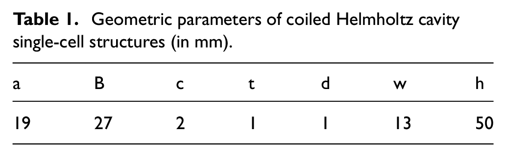
The coiled Helmholtz cavity basic unit designed in this paper consists of three perforated plates, two channel layers and an air back chamber, as shown in Figure 1(a) and (b). The first layer is the perforated plate, shown in Figure 1(c), with a square opening in the middle of the plate through which the sound waves enter. The second layer is the channel layer, shown in Figure 1(d), where the acoustic waves are transmitted from region 1 to region 2 along four paths and the position of region 1 corresponds to the opening in the first layer. The third layer is a perforated plate, shown in Figure 1(e), with four identical square openings, the position of which corresponds to region 2 of the second layer. Sound waves are transmitted from the third layer to the fourth layer, which has the same structural form as the second layer, but the transmission path of the sound waves is from region 2 to region 1, in contrast to the second layer. The fifth layer is a perforated plate identical to the first layer, through which acoustic waves are transmitted to the air back cavity. The specific dimensional parameters of the entire structure are shown in Table 1.
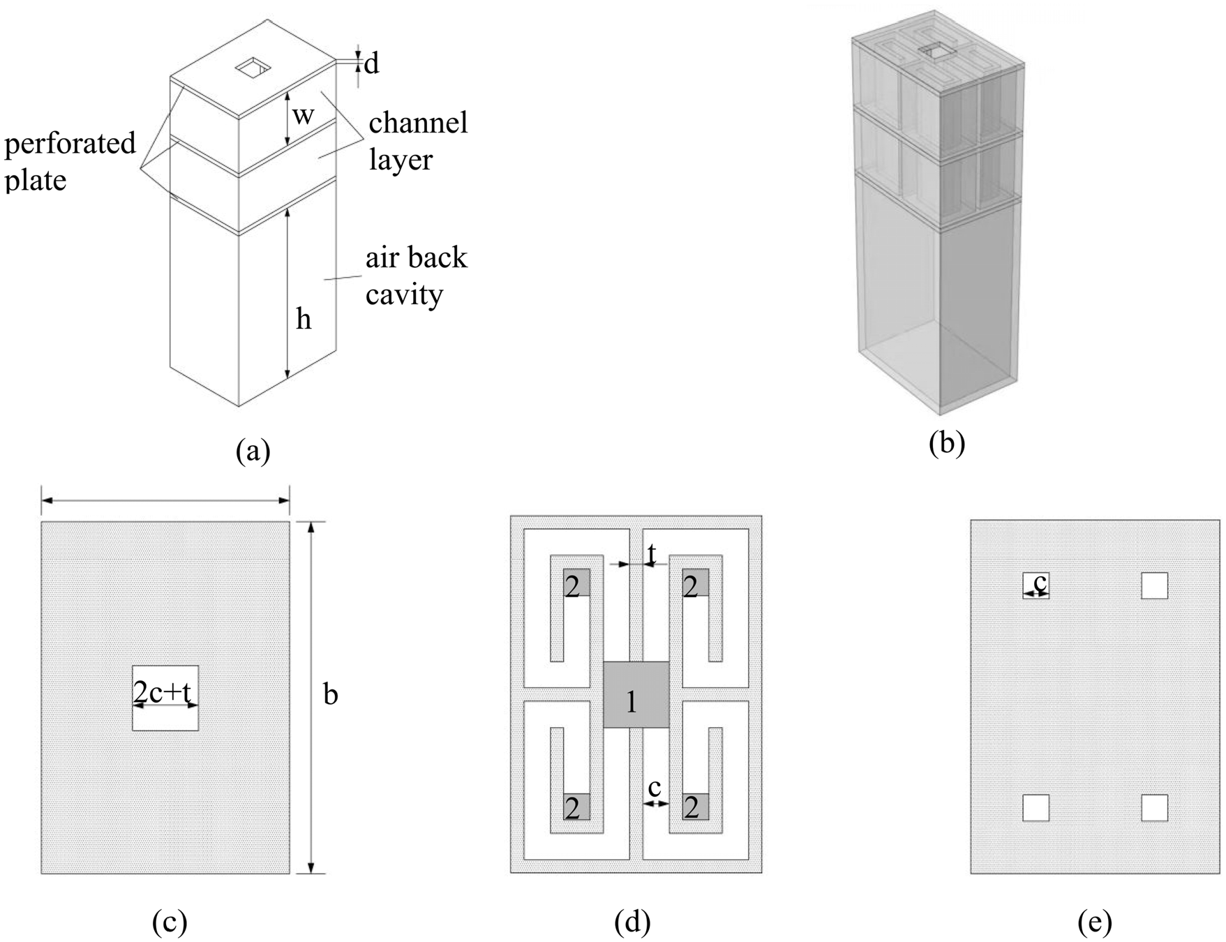
Structure of the coiled Helmholtz cavity acoustic metamaterial: (a) single-cell structure, (b) transparent schematic diagram, (c) first layer perforated plate, (d) second channel layer and (e) third layer perforated plate.
Geometric parameters of coiled Helmholtz cavity single-cell structures (in mm).
Analysis of the sound absorption mechanism
The Helmholtz cavity acoustic metamaterial is a structure consisting of a periodic arrangement of Helmholtz resonant cavities. The principle of sound absorption is as follows: when the incident frequency of the acoustic wave is the same as the intrinsic frequency of the Helmholtz cavity, the cavity resonates, the amplitude of the acoustic wave increases sharply, friction is generated with the wall at the neck, the acoustic energy is converted into thermal energy and dissipated, and the resonant frequency shows a strong sound absorption capacity. Figure 2 shows a typical Helmholtz resonator, which can be equivalent to the spring mass form shown in Figure 3 under the excitation of sound waves.

Helmholtz resonator.
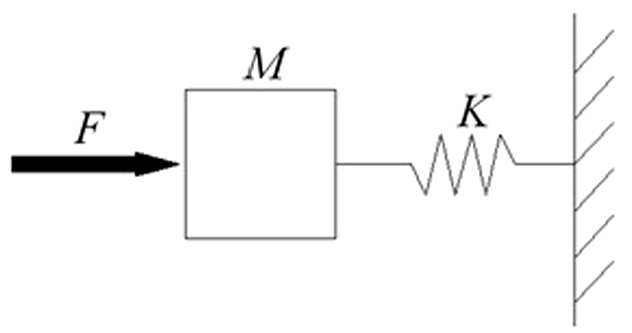
Spring mass system.
The force

where
When the air column in the neck tube of the Helmholtz resonator vibrates, both ends of the air column radiate sound waves to the outside of the resonator and the inside of the cavity. At this time, it is equivalent to the length of the neck tube air column being increased to

The equivalent stiffness

where
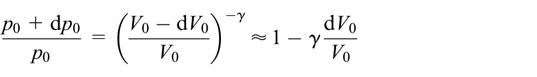
The conversion of acoustic energy to thermal energy is an equivalent adiabatic process, so the thermodynamic equation can be formulated as follows.

where
An approximation is as follows:
Therefore
where
Substituting equation (5) into equation (3) gives the equivalent stiffness as
The equivalent stiffness equation (6) and the equivalent mass equation (2) give the resonant frequency

As seen from equation (7), the resonant frequency of the Helmholtz resonant cavity depends on the volume of the closed cavity, the neck length and the cross-sectional area of the neck. To obtain low-frequency sound absorption, measures such as increasing the volume of the closed cavity, lengthening the length of the neck and reducing the cross-sectional area of the neck can be taken. In general, it is difficult to freely change the volume of the resonant cavity in practical situations due to space constraints during use. At the same time, it is easier to achieve low-frequency sound absorption performance by changing the neck characteristics of the resonant cavity. The basic Helmholtz cavity unit designed in this paper extends the transmission path of sound waves by changing the neck of the Helmholtz resonance cavity to a coiled channel, which is equivalent to increasing the length of the neck tube, thus achieving sound absorption at low frequencies.
The absorption coefficient is a physical quantity used to measure the ability of an object to absorb sound, which can best reflect the sound absorption performance of the object. When sound waves are projected from air into the surface of a dielectric material, the incident sound energy will be split into two parts. One part of the sound energy is absorbed by transmission into the interior of the object, and the other part cannot be absorbed and is reflected directly back. The ratio of the acoustic energy absorbed by the object to the incident acoustic energy is the absorption coefficient

where
From equation (8), it can be concluded that the absorption coefficient is a positive number less than 1. When the absorption coefficient is larger, the sound absorption effect of the material is better.
In general, the absorption coefficient can be derived from the acoustic impedance of the material, which is the ratio of the sound pressure (

where
When sound waves are normally incident on a material surface, the reflection coefficient

where
The sound absorption coefficient of a material

Analysis of the sound absorption propertiesof single-cell structures
Based on COMSOL multiphysics field coupling software, the finite element method is used to analyze the sound absorption characteristics of the basic unit of the coiled Helmholtz cavity. The effects of viscous and thermal losses in a narrow region are fully considered in the model, with the incident region on the outside of the structure set to the pressure acoustic domain, the internal air set to the thermal viscous acoustic domain and the structure boundary set to the solid mechanical domain. The incident acoustic wave is a plane wave with an incident pressure amplitude of 1 Pa that is incident on the surface of the structure in the negative z-axis direction. The perimeter of the sound-absorbing unit is set as a fixed constraint in the solid mechanics domain to simulate the forces on the structure in the impedance tube. The material chosen for the solid domain is ultraviolet (UV) curable resin with a Young’s modulus of 2650 MPa, a density of 1120 kg/m3 and a Poisson’s ratio of 0.41.
The sound absorption characteristics of the basic unit shown in Figure 1(a) were compared with those of the normal Helmholtz cavity, and the absorption coefficient curves are shown in Figure 4. The thickness dimensions of the normal Helmholtz cavity were kept the same as the basic unit shown in Figure 1(a), with the perforated plate square opening edge length set to 2 mm, the back cavity length set to 78 mm, and all plate and wall thicknesses set to 1 mm. As seen from Figure 4, a sound absorption peak appears at 266 Hz for the coiled Helmholtz cavity and at 318 Hz for the normal Helmholtz cavity. This shows that the coiled Helmholtz cavity can achieve a lower absorption peak frequency than the normal Helmholtz cavity with the same structure size, which has good application in the engineering field of low-frequency noise control.

Comparison of the sound absorption properties of single-cell structures and normal Helmholtz cavities.
To investigate the sound absorption mechanism at the absorption peak of the coiled Helmholtz cavity in Figure 4, the sound pressure levels at the absorption peak of 266 Hz and the nonabsorption peak of 400 Hz were calculated, and the distribution of the sound pressure levels is shown in Figure 5.

Sound pressure level distribution diagram: (a) at 266 Hz and (b) at 400 Hz.
Figure 5(a) shows the sound pressure level distribution of the single-cell structure at 266 Hz. From Figure 5(a), it can be seen that the maximum value of sound pressure in the metamaterial structure is inside the cavity, and the sound pressure in the coiled channel layer gradually increases from the noise incident end to the cavity. The characteristics of the sound pressure distribution are similar to those of a normal Helmholtz cavity at resonance, which indicates that the coiled channel layer in the metamaterial structure is equivalent to extending the length of the neck tube of the Helmholtz resonant cavity to achieve lower frequency absorption when the cavity resonates.
Figure 5(b) shows the sound pressure level distribution of the single-cell structure at 400 Hz. From Figure 5(b), it can be seen that the maximum sound pressure level at this time is 96.5 dB, which is smaller than the maximum sound pressure level of 120 dB at 266 Hz. Therefore, the cavity resonance at a frequency of 266 Hz is the reason for the excellent sound absorption performance of the metamaterial structure near this frequency.
Factors influencing the absorption coefficient of coiled Helmholtz cavity acoustic metamaterials
Variations in the structural parameters of coiled Helmholtz metamaterials greatly influence their sound absorption performance. In this section, the cases of structural channel layer thickness and back cavity length are analyzed separately, and the calculated absorption coefficient curves of the metamaterial structure are shown in Figure 6(a) and (b).

Effect of structural parameters on the sound absorption coefficient: (a) effect of channel layer thickness on sound absorption performance and (b) effect of back cavity length on sound absorption performance.
For the single-cell structure shown in Figure 1(a), the effect of the channel layer thickness w on the sound absorption performance of the metamaterial structure is analyzed for thicknesses of 7, 9, 11, and 13 mm while keeping the plate thickness (d = 1 mm), wall thickness (t = 1 mm), and back cavity length (h = 50 mm) constant. Figure 6(a) shows that as the channel layer thickness increases, the sound absorption peak of the metamaterial moves toward higher frequencies, and its peak value gradually increases. Increasing the thickness of the channel layer corresponds to increasing the cross-sectional area of the opening of the Helmholtz resonance cavity, which increases the resonant frequency according to equation (7). In addition, with increasing channel layer thickness, the effective sound velocity in the channel increases, which makes the first sound absorption peak increase.
For the single-cell structure shown in Figure 1(a), the effect of the back cavity length h on the sound absorption performance of the metamaterial structure is analyzed for lengths of 30, 40, 50, and 60 mm while keeping the plate thickness (d = 1 mm), wall thickness (t = 1 mm) and channel layer thickness (w = 13 mm) constant. Figure 6(b) shows that as the back cavity length increases, the absorption peak shifts to lower frequencies. The air cavity can be regarded as a spring in a spring oscillator system, and as the cavity length increases, the equivalent spring stiffness decreases, and the frequencies of the absorption peaks shift to lower frequencies with essentially constant equivalent mass. In addition, a change in the cavity length has essentially no effect on the peak absorption.
Synergistic coupling sound absorption mechanism of the coiled Helmholtz cavity metamaterial structure
Synergistic coupling of two units
As the peaks and valleys in the absorption curve always occur in pairs, the presence of the valleys will narrow the absorption band and worsen the absorption effect, so a broadband absorption performance of the structure can be achieved through a synergistic coupling mechanism. By combining several coiled Helmholtz cavities with peaks at different frequencies, the units can be synergistically coupled to achieve a broadband sound absorption effect.
To verify the multiunit synergistic coupling sound absorption mechanism, a two-unit parallel structure was designed, as shown in Figure 7. The cross-sectional size of both units is 34 × 44 mm, the wall thickness and perforated plate thickness are both 1 mm, and the channel width in the channel layer is 4.5 mm. The channel layer thickness of unit 1 is 6 mm, and the cavity length is 45 mm. The channel layer thickness of unit 2 is 7 mm, and the cavity length is 43 mm. The comparison of the sound absorption coefficient between the single structure and parallel structure is shown in Figure 8, in which the sound absorption peak of unit 1 is at 180 Hz and its peak is 0.995, the sound absorption peak of unit 2 is at 198 Hz and its peak is 0.994, and the two sound absorption peaks of the parallel structure are at 182 and 200 Hz and their peaks are 0.978 and 0.988, respectively. Through comparative analysis, it can be found that the sound absorption peak frequency of the parallel structure basically corresponds to that of the single structure, and the peak value is basically the same, but the sound absorption band of the parallel structure is significantly wider. This shows that the broadband sound absorption effect can be achieved by coupling multiple basic units in parallel.

Two-unit parallel structure.

Comparison of sound absorption coefficients for single structures and parallel structures.
Multiunit synergistic coupling
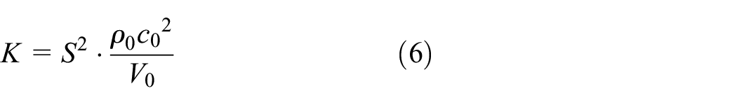
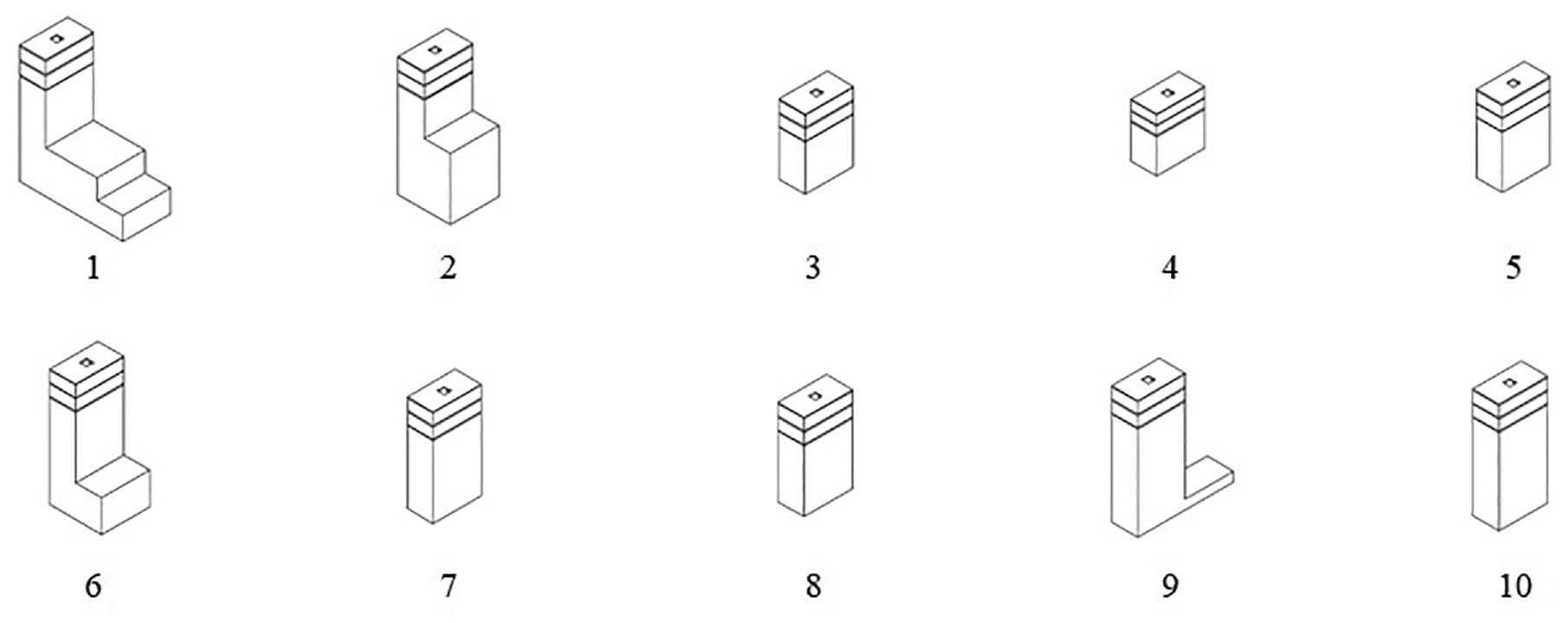
Based on the synergistically coupled sound absorption mechanism verified, three multiunit coupled structures are designed in this section to achieve broadband sound absorption of the structure. The first multiunit coupled structure is shown in Figure 9, and its split structure is shown in Figure 10. Figures 9 and 10 show that the coupled structure is composed of 11 basic units, each of which consists of two channel layers and three perforated plates, and the wall thickness and the perforated plate thickness are set to 1 mm. Units 1–4 have a cross-sectional size of 32 × 22 mm, the first perforated plate has a 6 mm edge square opening, and the third perforated plate has a 2.5 mm edge square opening. Units 5–11 have a 4 mm edge square opening in the first perforated plate and a 1.5 mm edge square opening in the third perforated plate, in which the cross-sectional size of unit 9 is 32 × 16 mm, and the cross-sectional size of the other units is 16 × 16 mm. To make full use of the model space, the air back cavities of some of the units were designed in a folded form, and the total section size of the parallel structure was 76 × 64 mm, with a total height of 101 mm. The remaining structural parameters of the 11 units are shown in Table 2.

The first multiunit coupled structure.
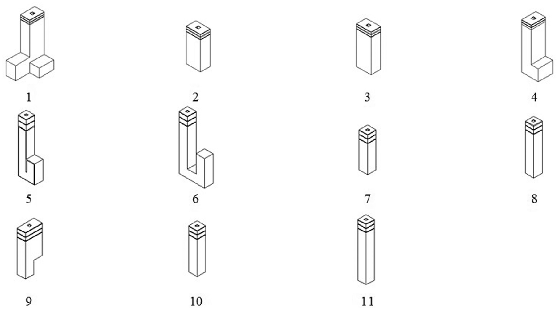
Structure splitting diagram of the first multiunit coupled structure.
Structural parameters of the 11 parallel units (in mm).

It should be noted that the absorption peak frequency of a metamaterial structure is related to the air volume of the back cavity. Regardless of whether the back cavity is a straight cavity or a folded cavity, the absorption peak frequency remains the same as long as the back cavity volume is the same. Therefore, in this paper, the cavity length of the folded cavity unit is converted into a straight cavity length under the same back cavity volume.
The finite element method was used to analyze the sound absorption characteristics of the designed multiunit coupled structure shown in Figure 9, and the results are shown in Figure 11. Figure 11 shows that the absorption band consists of 11 absorption peaks. Each sound absorption peak is provided by a basic unit, and the absorption peak of each unit corresponds to a different frequency. The peak complementarity is realized by increasing the number of units to broaden the sound absorption band. The first multiunit coupled structure designed in this paper can achieve good broadband sound absorption in the 90–360 Hz frequency band, with an average absorption coefficient of 0.624 and a maximum absorption coefficient of 0.775 in the effective frequency range.

Sound absorption coefficient of the first multiunit coupled structure.
The second multiunit coupled structure is shown in Figure 12, and its split structure is shown in Figure 13. Figures 12 and 13 show that the coupled structure is composed of 10 basic units, each of which contains two channel layers and three perforated plates, and the wall thicknesses and the perforated plate thicknesses are both set to 1 mm. Each unit has a cross-sectional size of 22 × 41 mm, the first perforated plate has a 6 mm edge square opening, and the third perforated plate has a 2.5 mm edge square opening. The air back cavity of a part of the unit is also set as a folded form. The total section size of the coupled structure is 110 × 82 mm, and the total height is 101 mm. The remaining structural parameters of the 10 units are shown in Table 3.
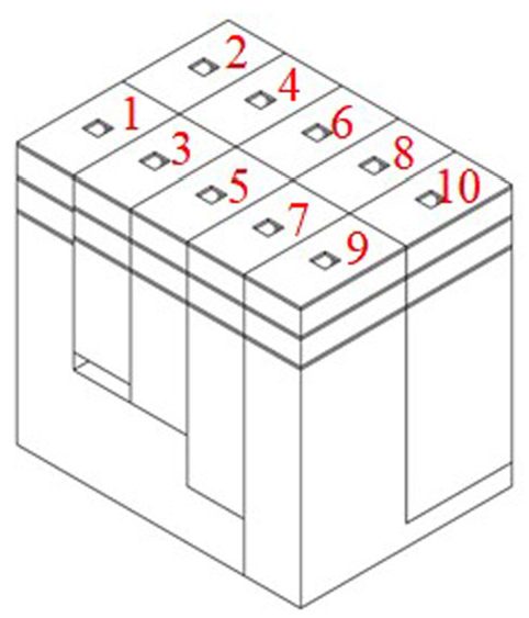
The second multiunit coupled structure.
Structure splitting diagram of the second multiunit coupled structure.
Structural parameters of the 10 parallel units (in mm).

The absorption coefficients were calculated for the second multiunit coupled structure shown in Figure 12, and the results are shown in Figure 14. Figure 14 shows that the absorption curve consists of 10 absorption peaks, and each sound absorption peak is provided by a basic unit, which achieves a better broadband absorption performance in the 100–220 Hz frequency band with an average absorption coefficient of 0.741 and a maximum absorption coefficient of 0.883.
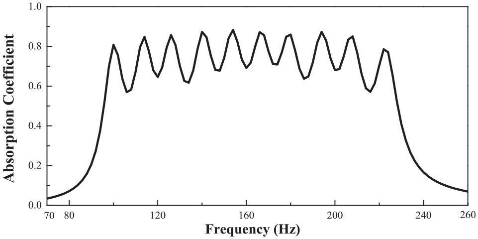
Sound absorption coefficient of the second multiunit coupled structure.
The third multiunit coupled structure is shown in Figure 15, and its split structure is shown in Figure 16. Figures 15 and 16 show that the coupled structure is composed of six basic units, each of which contains two channel layers and three perforated plates, and the wall thickness and the perforated plate thickness are both set to 1 mm. Each unit has a cross-sectional size of 22 × 32 mm, the first perforated plate has a 6 mm edge square opening, and the third perforated plate has a 2.5 mm edge square opening. The air back cavity of a part of the unit is also set as a folded form, the total section size of the coupled structure is 66 × 64 mm, and the total height is 67 mm. The remaining structural parameters of the six units are shown in Table 4.

The third multiunit coupled structure.

Structure splitting diagram of the third multiunit coupled structure.
Structural parameters of the six parallel units (in mm).

The absorption coefficient was calculated for the third multiunit coupled structure shown in Figure 15, and the results are shown in Figure 17. Figure 14 shows that the absorption curve consists of six absorption peaks, and each sound absorption peak is provided by a basic unit, which achieves a better broadband absorption performance in the 200–300 Hz frequency band with an average absorption coefficient of 0.785 and a maximum absorption coefficient of 0.933.

Sound absorption coefficient of the third multiunit coupled structure.
Table 5 gives the comparative data of the three multiunit coupled structures in terms of the sound absorption band, average absorption coefficient, and structure height. Table 5 shows that the 11-unit coupled structure has the same overall height as the 10-unit coupled structure. The former has a wider effective absorption band, and the latter has a larger average absorption coefficient. This shows that when the structure size is kept constant, the sound absorption bandwidth and sound absorption coefficient restrict each other, and the sound absorption bandwidth can be widened by reducing the sound absorption coefficient. The average sound absorption coefficient of the 10-unit coupled structure is basically the same as that of the six-unit coupling structure. The former has a lower sound absorption frequency, but the latter has a smaller structure height of only 67 mm. This shows that the absorption frequency band and the structure size restrict each other, and a larger structure size can achieve a lower absorption performance.
Comparison of three multiunit coupled structures.

A comparative analysis of the sound absorption performance of the three multiunit coupled structures in Table 5 shows that the structural absorption efficiency, sound absorption bandwidth, and structural size are interrelated and mutually restrictive. A larger structure size can improve the absorption efficiency and broaden the absorption bandwidth, but a larger structure size cannot meet the actual needs of the project. In addition, if the sound absorption bandwidth is to be widened, then the absorption efficiency will inevitably be reduced. Therefore, it is a difficult task in this paper to design a sound-absorbing structure that meets our needs by balancing sound absorption efficiency, sound absorption bandwidth and structure size with ingenious design. In this paper, based on the requirements of small size and low-frequency noise control of a marine acoustic material structure, we select the appropriate structure height, precisely regulate the peak and frequency band of sound absorption, and design a metamaterial structure suitable for low-frequency noise absorption of ships to provide design ideas for the field of low-frequency noise control of ships.
Effect of porous materials on the sound absorption properties of metamaterial structures
The principle of synergistically coupled sound absorption is used to combine multiple structural units with absorption peaks at different frequencies through a strict dimensional design, successfully designing a low-frequency broadband sound absorption structure suitable for the field of ship noise reduction engineering and achieving effective control of low-frequency noise. In the field of ship noise reduction, the frequency of ship noise can reach several thousand Hz, so how to simultaneously take into account low-frequency and high-frequency sound absorption is also a difficult problem. Porous materials play an important role in the field of noise reduction, and their effect on high-frequency noise absorption is obvious. In this section, a composite space folding metamaterial structure is designed by embedding a multiunit coupled structure into the porous material, and its sound absorption properties are explored.
Introduction to porous materials
Porous materials include melamine foam, sponges, and rock wool boards, which are characterized by a large number of interconnected pores inside the material. The sound absorption mechanism of porous materials is that the incident sound wave will cause air vibration in the material pores. During vibration, the air and the pore wall will produce friction and viscous resistance so that part of the sound energy can be converted into heat energy and dissipated to achieve the effect of sound absorption and noise reduction. The Johnson-Champoux-Allard equivalent model is used in acoustic simulations to study the sound absorption properties of porous materials. The model contains five parameters: porosity
The relationship between the equivalent density
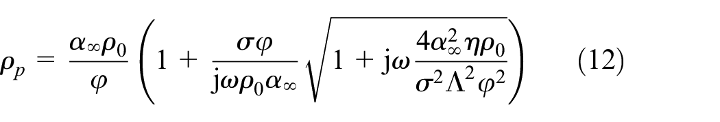

where
The characteristic impedance
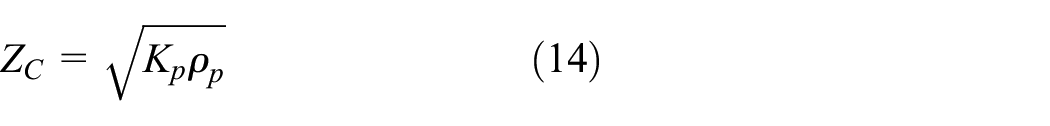

The expression of the surface impedance of porous material

where
Based on equation (11), the sound absorption coefficient
Composite space folding metamaterial structures
The six-unit coupled structure in Figure 15 is used as the object of study and is embedded in a porous material to construct a composite space folding metamaterial structure, whose three-dimensional structure is shown in Figure 18. The cross-sectional size of the six-cell coupled structure is 66 × 64 mm, and the width of the porous material in which the coupled structure is embedded is b1, so the cross-sectional size of the porous material is (66 + 2b1) × (64 + 2b1) mm, as shown in Figure 19. The sectional view in Figure 20 shows that the porous area can be divided into upper, middle, and lower layers, in which the upper and lower porous material thicknesses are l1 and l2, respectively, the middle layer of porous materials has a built-in coupled structure, its thickness is the height of the coupled structure, and the total height of the upper, middle, and lower layers of porous materials is L. The specific values of the model geometry are shown in Table 6. The porous material used in this paper is melamine foam, and its acoustic parameters set in the finite element analysis software COMSOL are shown in Table 7.
Schematic diagram of the three-dimensional structure.
Top view.

Sectional view.
Geometrical parameters of the composite space folding metamaterial structures (in mm).

Melamine foam material parameters.

The finite element method was used to calculate the sound absorption performance of the pure foam, the six-unit coupled structure and the composite space folding metamaterial structure, and the comparison results of the absorption coefficient curves are shown in Figure 21. It should be noted that when simulating these three structures, the incident area was kept consistent to ensure the accuracy of the comparison results, and here, the incident area was 86 × 84 mm.

Graph of the sound absorption coefficient.
As seen from Figure 21, the absorption coefficient of pure foam gradually increases from low to high frequencies and has a good absorption effect above 400 Hz, but the absorption effect below 400 Hz is less satisfactory. The curve of the composite space folding metamaterial structure above 345 Hz is basically similar to that of the pure foam, but the curve decreases slightly, which is mainly due to the reduced volume of the foam caused by the coupled structure built into the composite space folding structure, so the absorption coefficient decreases slightly. In the frequency range of 130–345 Hz, the composite space folding metamaterial structure has a clear advantage over pure foam, mainly due to the interaction between the built-in six-unit coupled structure and the porous material, which enhances the low-frequency absorption performance. Below 130 Hz, the sound absorption curve of the composite space folding metamaterial structure remains basically the same as that of the pure foam. In addition, Figure 21 shows that the six-unit coupled structure has six obvious absorption peaks in the range of 200–300 Hz, while the composite space folding structure has less obvious absorption peaks and the curve is smooth in this frequency band, but the average absorption coefficients of both are basically the same in this frequency band.
Therefore, the comparative analysis shows that the enhanced sound absorption performance of the composite space folding structure in the low-frequency band is caused by its built-in coupled structure. The results obtained are in accordance with the expectations of the structural design, where the coiled Helmholtz cavity achieves low-frequency sound absorption and the porous material achieves high-frequency sound absorption, combining the two to achieve a large broadband sound absorption effect above 200 Hz, which has good prospects for application in the field of engineering noise reduction.
Experimental tests
Verification of the synergistically coupled sound absorption mechanism
Sound absorption performance experiments were carried out using a Soundwave SW422 impedance tube test system, shown in Figure 22, with a circular impedance tube and a cross-sectional diameter of 100 mm. The whole test system consists of a sound pressure calibrator, a VA-Lab test system, a standing wave tube, a power amplifier, and a microphone.
SW422 test system.
Using the two-unit coupled structure in Figure 7 as the experimental object, a 3D printing technique was used to produce the experimental model. The 3D printed model of the two-unit coupled structure is shown in Figure 23. To place the two-unit coupled structure with a rectangular cross section into an impedance tube with a circular cross section for testing, the coupled structure needs to be designed as a cylindrical shape, as shown in Figure 24, and its 3D printed model is shown in Figure 25. Here, the coupled structure is placed in a hard boundary material frame and placed in the impedance tube for testing. The hard boundary material used here and the plate used for the cell structure are both UV curable resins. To fit the model into the circular impedance tube, the cross-sectional diameter of the model in Figure 25 was set to 99.4 mm.

3D model of a two-unit coupled structure.

Geometric model for experimental testing of a two-unit coupled structure.

3D model for experimental testing of a two-unit coupled structure.
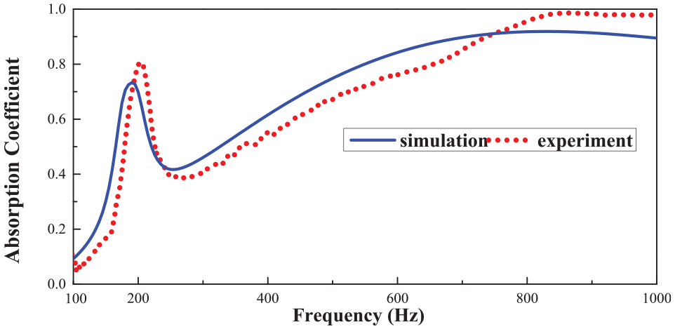
The sound absorption coefficient comparison of the two-unit coupled structure between the simulation and experiment is shown in Figure 26. Figure 26 shows that the experimental absorption coefficient curve has two absorption peaks at 194 and 208 Hz with peak values of 0.857 and 0.941, respectively, while the simulated sound absorption coefficient curve has two sound absorption peaks at 180 and 198 Hz with peak values of 0.977 and 0.988, respectively. Through a comparison between the experiment and simulation, there are certain differences in the frequency and peak value of the sound absorption peak. Due to the machining error of the model, the peak of the experimental sound absorption curve moves to high frequency. In addition, because the impedance tube is round, limited by experimental equipment, the model is printed as a cylinder, and the hard boundary material is hollow, resulting in experimental errors. However, Figure 26 shows that the two curve trends of the experiment and simulation have good consistency, which verifies the correctness of the synergistic coupling sound absorption mechanism.
Comparison of the sound absorption coefficient of a two-unit coupled structure between simulation and experiment.
Design and experimental study of a multiunit coupled structure
In the previous section, it was verified by experimental methods that the coupled structure can achieve broadband sound absorption. In this subsection, a multiunit coupled structure is designed, the corresponding model is prepared by 3D printing technology for sound absorption tests, and the test results are compared and analyzed with the absorption coefficients obtained from the simulation.
The geometric model and the 3D printed model of the designed multiunit coupled structure are shown in Figures 27 and 28. Each basic unit in Figures 27 and 28 is set up with two channel layers and three perforated layers, and the wall thickness and perforated plate thickness are set to 1 mm. Units 1–4 have a cross-sectional size of 32 × 22 mm, the first perforated layer has a 6 mm edge square opening, and the third perforated layer has a 2.5 mm edge square opening. Units 5–11 have a 4 mm edge square opening in the first perforated plate and a 1.5 mm edge square opening in the third perforated plate, in which the cross-sectional size of unit 9 is 32 × 16 mm, and the cross-sectional size of the other units is 16 × 16 mm. The remaining structural dimensions of the 11 basic units are shown in Table 8. In the structural design, the absorption peaks of each basic unit are kept at different frequencies to achieve complementary peaks, thus effectively broadening the absorption band.
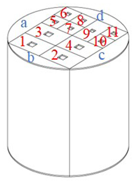
Geometric model of a multiunit coupled structure.
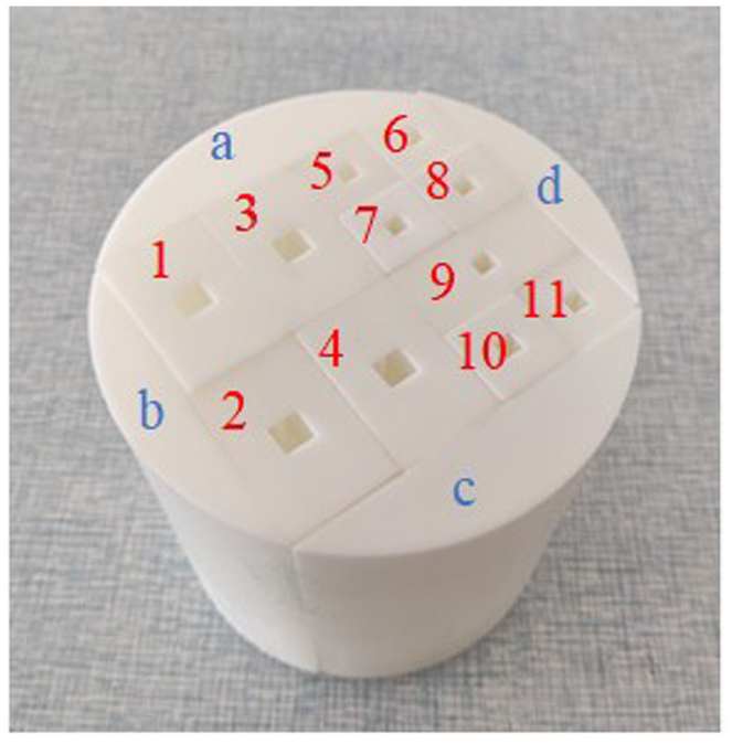
3D model of a multiunit coupled structure.
Structural parameters of the 11 basic units (in mm).

To make full use of the model space, the air back cavities of some of the units were designed in a folded form. The cross section of the 11-unit coupled structure is 76 × 64 mm, but the impedance tube used in the experiment is circular, so the metamaterial model is designed as a cylinder with a section diameter of 99.4 mm and a height of 101 mm. To make full use of the material space, structures a, b, c and d in Figure 27 are set to be hollow with a wall thickness of 1 mm, and the three structures a, b, and c are connected with the air back cavities of basic units 1, 2, and 4, respectively, to increase the volume of the back cavities. The split structure of the multiunit coupled model and its 3D printing model are shown in Figures 29 and 30, respectively.

Split structure physical diagram of a multiunit coupled structure.

Structure splitting diagram of a multiunit coupled structure.
The acoustic absorption performance of the multiunit coupled metamaterial structure shown in Figure 28 was tested, and the comparison between the acoustic absorption coefficient of the metamaterial structure measured in the experiment and the numerical simulation is shown in Figure 31. The solid line in the Figure 31 shows the simulation calculation result. The sound absorption band of the coupled structure consists of 11 absorption peaks, each of which is provided by a basic unit to achieve peak complementarity, thus achieving a good broadband absorption effect in the 90–360 Hz frequency band. The dashed line in the Figure 31 shows the experimentally measured results. The curve trend is basically the same as that of the simulation curve, the average absorption coefficient is also similar, and the broadband sound absorption effect of 90–360 Hz is also achieved. Therefore, there is good consistency between the two curves.

Comparison of the simulated and experimental sound absorption coefficients for multiunit coupled structures.
The absorption peak of the absorption coefficient curve measured in the experiment is not prominent, as shown in Figure 31, and the reasons are as follows.
In the simulation, each basic unit is capable of absorbing sound waves at a specific frequency, and the multiunit coupled structure obtains an absorption band consisting of multiple absorption peaks. However, due to the structural differences between the experiment and the simulation, the sound absorption peak frequency measured in the experiment cannot fully correspond to the simulation calculation results, which causes the physical model to show only one absorption peak when the two absorption peak frequencies are too close or a sound absorption valley when the two absorption peak frequencies are too far away. However, as seen in Figure 31, the first four absorption peaks are larger and the last seven are smaller in the absorption curve obtained from the simulation, while the absorption curve obtained from the experiment is also larger in the first four absorption peaks and smaller in the last seven. Although the experimental absorption curve does not highlight the position of each peak, the overall trend of the curve is consistent with the results obtained from the simulation, and the average absorption coefficient in the effective absorption band is basically the same, so the results of this experiment are accurate and valid.
Experimental study of the sound absorption properties of pure porous materials
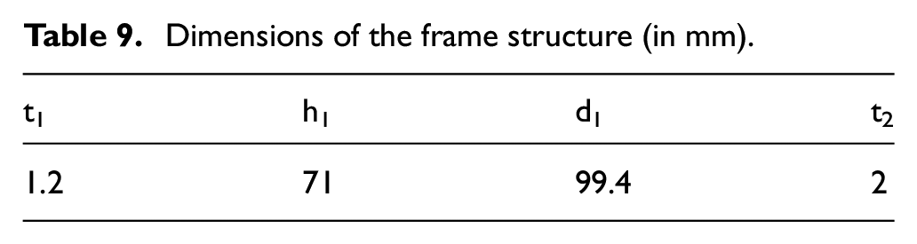
Porous materials can achieve high-frequency sound absorption, and this section tests the sound absorption performance of pure porous materials to verify their high-frequency sound absorption performance. The geometric model used for the experimental tests is shown in Figure 32. The geometric model is divided into two parts: the frame and the foam material. The frame is made by 3D printing technology, and the material used is UV curable resin. The foam material is selected as melamine foam, and its material parameters are shown in Table 7. The thickness of the frame sidewall plate is set as t1, the height as h1, the outer diameter as d1, and the thickness of the frame bottom cover as t2. Its specific values are shown in Table 9. The frame structure and porous material samples are shown in Figure 33. It should be noted that the porous material is filled in the frame to make it easier to fix in the impedance tube.

Geometric model of pure foam for the experimental test.
Dimensions of the frame structure (in mm).

3D model of pure foam for the experimental test.
Melamine foam with a thickness of 71 mm was selected to be mounted in the frame and tested with an impedance tube to obtain the absorption coefficient curve shown in Figure 34. Figure 34 shows that the sound absorption coefficient curve measured in the experiment gradually increases from low frequency to high frequency, and the sound absorption coefficient decreases between 250 and 500 Hz compared with the simulation, which is mainly due to the influence of frame resonance. However, by comparing the experimental results with the simulated results, it can be seen that the overall trends of the two curves are basically the same, which is in good agreement, indicating that the experimental results are more accurate and proving the correctness of the material parameters.

Comparison of the simulated and experimental sound absorption coefficients for pure foam.
Experimental study of two-unit composite space folding metamaterials
A simple two-unit composite space folding metamaterial structure was prepared by embedding the two-unit coupled structure into the porous material. Its geometric model is shown in Figure 35, and the real object is shown in Figure 36. Figures 35 and 36 show that the porous material is divided into three layers. The upper and lower layers are both 5 mm thick, and the middle layer is embedded with the metamaterial structure, the thickness of which is the same as the height of the coupling structure, which is 61 mm, so the total height of the structure is 71 mm.
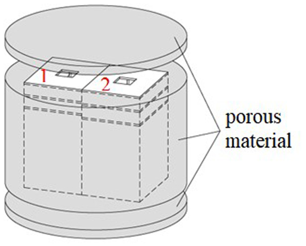
Geometric model of a two-unit composite space folding metamaterial structure.

3D model of a two-unit composite space folding metamaterial structure.
The two-unit composite space folding metamaterial structure was fitted into the frame prepared in Figure 33 and placed into an impedance tube for sound absorption performance testing, and the absorption coefficient curve was obtained, as shown in Figure 37. Figure 37 shows that there is a certain deviation between the sound absorption peaks of the two curves at low frequencies. The sound absorption peak of the simulation curve is at 190 Hz, and the peak value is 0.73. The sound absorption peak of the experimental curve is at 204 Hz, and the peak value is 0.81. However, the overall trends of the two sound absorption coefficient curves obtained by the experiment and simulation are basically the same, with good consistency.
Comparison of the simulated and experimental absorption coefficients of a two-unit composite space folding metamaterial structure.
As the coupled structure consists of two basic units, it should produce two consecutive absorption peaks at low frequencies, but in Figure 37, both the simulation and the experimental absorption coefficient curves show only one absorption peak for the following reasons. The foam covering the surface of the metamaterial structure can suppress the evanescent wave at the anti-resonance and thus increase the sound absorption valley value. On the other hand, it can increase the loss factor of the system and break the original critical coupling condition, thus reducing the sound absorption peak value. Therefore, the curve at the frequency of two acoustic absorption peaks becomes flatter, showing only one acoustic absorption peak, but its sound absorption bandwidth is the same as that of the original two sound absorption peaks.
To verify the correctness of the combination of the metamaterial structure and the porous material to broaden the absorption bandwidth, a comparison of the experimentally measured absorption coefficient curves is plotted, as shown in Figure 38, and the corresponding simulation calculation results are shown in Figure 39. Figures 38 and 39 show that the two-unit composite space folding structure has a high absorption coefficient at high frequencies and the curve is basically the same as the pure foam absorption coefficient curve. In addition, it produces an absorption peak at low frequencies, and its bandwidth is basically the same as the bandwidth composed of two consecutive absorption peaks of the coupled structure. Although there are small differences between the experimental results and the simulation results, they are consistent overall. The same conclusion can be drawn; that is, the composite space folding metamaterial structure can take into account both low-frequency sound absorption and high-frequency sound absorption. Its low-frequency sound absorption performance is determined by the metamaterial structure, and its high-frequency sound absorption performance is determined by the porous material.
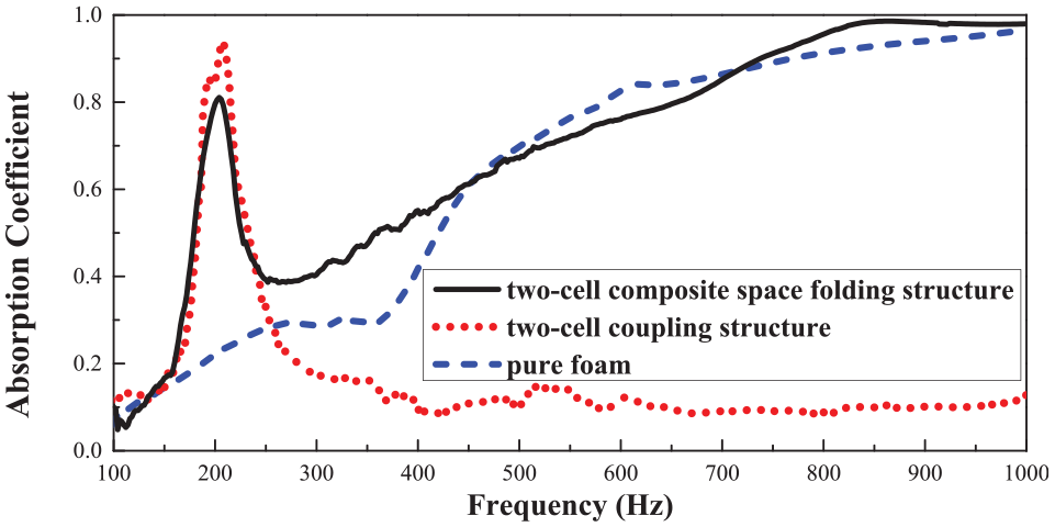
Experimental comparison.

Simulation comparison.
Conclusions
For low-frequency noise control of ships and thickness size limitations of acoustic materials, this paper designs a multiunit synergistically coupled metamaterial structure based on a coiled type and Helmholtz cavity acoustic metamaterial structure. A comparison of the sound absorption performance of the coiled Helmholtz cavity metamaterial structure with that of a normal Helmholtz cavity shows that the structure can obtain lower absorption peak frequencies. By investigating the effect of the variation in parameters such as the channel layer thickness and the back cavity length on the acoustic performance of the structure, the trend of the variation in the acoustic performance of the coiled Helmholtz cavity acoustic metamaterial with the parameters of the cell structure is obtained. In this paper, three multiunit coupled structures are designed to achieve low-frequency broadband sound absorption performance through strict dimensional design, with the absorption peaks of different cells corresponding to different frequencies to achieve peak complementarity. In addition, the multiunit coupled structure is built into the porous material to achieve a large broadband sound absorption effect above 200 Hz. Although the acoustic performance of the coiled Helmholtz cavity acoustic metamaterial designed in this paper is limited, it has the characteristics of a small structure size, a low-frequency band, and a wide-frequency band, so it has good prospects for application in marine engineering noise reduction.
Footnotes
Acknowledgements
We would like to thank the editor and the anonymous reviewers for their helpful suggestions and comments.
Handling Editor: Chenhui Liang
Declaration of conflicting interests
The author(s) declared no potential conflicts of interest with respect to the research, authorship, and/or publication of this article.
Funding
The author(s) disclosed receipt of the following financial support for the research, authorship, and/or publication of this article: This work was supported by Fundamental Research Funds for the Central Universities in P. R. China [Grant number DUT20LAB308].