
Abstract
In order to guarantee the running safety of the train on the bridge in the wind field the wind-proofing barrier is generally installed on the bridge, however, in the transition section where a train enters or exits the wind-proofing barrier the wind load on the car-body will suddenly change because of a sudden change of wind field. This will cause the train swaying, reduce the driving comfort, and even endanger the driving safety in severe cases. Therefore, it is necessary to optimize the wind barrier design in the transition section. Firstly the dynamic interaction model of vehicle-bridge-wind barrier coupling system under wind load is established, and the influence of sudden change of wind forces acting on the train on the driving safety is analyzed, then some concrete measures are proposed with respect to improving the driving comfort and safety and the effect of the optimizing measures is evaluated. Taking 12-span simply supported box girder bridges installing single-side 3.5 m wind barrier as an example, and optimizing the design of wind barriers in the transition section, the dynamic response and the driving safety indices of the train are obtained according to the above calculation model. The results before and after the optimization design of the wind barrier in the transition section are compared. It can be found that the sudden change of wind forces on the train induced by wind barrier has a significant effect on the lateral acceleration of the train, especially when the train is moving in and out of the wind barrier. The driving safety indices with gradual wind barriers are smaller than those without optimization design in the transition section of wind barrier.
Keywords
Introduction
The overturning accidents of railway trains due to strong wind occur from time to time. For example, around 30 train accidents occurred from 1872 to 2006 in Japan and a dozen trains were withdrawn from the schedule each year in China. 1 In addition, train accidents were frequently reported to be caused by strong winds in Spain, Switzerland, the USA, France, and India. 2 Particularly in recent years, with the rapid development of modern railway transportation systems, the three characteristics of modern high-speed railway trains have greatly affected their cross-wind running safety, including: (1)The lightweight structure of trains. Lightweight increases the technical and economic benefits of railway vehicles, reduces energy consumption and wheel-wear, etc. However, since the resistance to prevent the train from overturning in the crosswind is mainly provided by gravity, the lightweight structure of trains reduces the crosswind stability; (2) The high running speed of trains. As the speed of the train increases, the travel time for passengers is shortened, but the relative oncoming wind speed of the train and the associated aerodynamic loads are increased; (3) The power distributed traction of trains. The distributed traction form improves the traction performance of the train, but the lead car that suffers from the most dangerous wind loads is no longer a high-mass locomotive, but a lighter-mass vehicle. These characteristics are very unfavorable for the anti-overturning of the train under strong crosswinds. So the running safety of the high-speed train under cross wind has always been a hot research topic.2–5 In order to improve the running safety of the train, one of the most effective ways to reduce the wind effects is by placing screens or windbreaks, either solid or porous, upstream the elements to be protected. And the operation experience of Shinkansen in Japan has shown that the installation of wind barriers can greatly improve the safety of train under cross-wind and reduce the stop time of trains in the wind field.6,7 However, when the train enters or exits the wind barrier installing on the railway infrastructure, the wind barrier causes sudden changes in the wind load acting on the train, which will significantly affect the driving safety and passenger comfort, such as car-body swaying greatly, 8 and even derailment in severe cases.
The research on the running safety of train on the bridge in the wind field is mainly divided into two aspects, namely the aerodynamic characteristic analysis of the vehicle-bridge coupling system, and the calculation of dynamic response and the evaluation of the running safety of the train. In order to obtain the aerodynamic characteristics of the vehicle-bridge coupling system, wind tunnel tests, numerical simulation method (Calculation Fluid Dynamics Method), and on-site model tests can be used. Plenty of aerodynamic data and surface pressure distribution are given for different vehicle types and bridge structures.9–18 At the same time, some researchers have established a wind-induced train operation safety analysis model to calculate the vibration response of the train and bridge.19–23
From the coupling analysis of the wind-vehicle-bridge system, the researchers found that the high-speed train will derail or overturn when the vehicle speed or wind velocity reaches a certain limit value, so the design of the wind barrier came into being.24,25 Some scholars have designed different forms of wind barriers for the operation safety of high-speed trains on the bridge, and studied the mechanical performance of wind barriers and their protection capability for high-speed train through wind tunnel tests and numerical simulation methods.26–28 The change law of the aerodynamic characteristics of the bridge and the train, and its influence on the driving safety of the train are also discussed, then the design reference parameters of wind barriers installing on railway bridges are advised to ensure safe operation of trains in strong wind area according to wind-vehicle-bridge interaction theory.29,30 And Ref. 31 also has progressed some research work on the running safety of the train with wind barrier on the railway bridge and analyzed the influence on train safety and passenger comfort considering the sudden change of the wind loads on the car-body induced by the wind barrier, the analysis results show an increased risk of overturning when the train enters or exits the wind barrier, also known as the transition section, and reduced ride comfort.
As described above, due to the installation of the wind barrier, the wind forces on the train will be greatly reduced, which greatly enhances the safety of train operation and reduces the stop time of the train. However, when the train enters or leaves the wind barrier, the wind load acting on the train changes suddenly due to the shielding of wind barriers. This change may lead to excessive swaying of the car-body, causing driving discomfort and even driving safety problems. Therefore, it is very necessary to properly design the wind barrier in the transition section to ensure driving safety and passenger comfort.
In this paper, the calculation formulas of the wind forces acting on the car-body are derived during the whole process from the train entering to exiting the wind barrier, and the coupled model of the wind-vehicle-bridge system is built and the relevant calculation program is written. On basis of the established wind-vehicle-bridge coupling model with the wind barrier the driving safety of the train and passenger comfort considering the sudden change of the wind force on the train is calculated in the transition section, then the design parameters of the wind barrier in the transition section are optimized. Finally, the vibration response and safety evaluation indices of the train are obtained for a 12-span simply-supported box girder bridge whether the specific design of wind barrier in the transition section is realized, and appropriate conclusions from the research are proposed.
Sudden change of wind force on the train induced by wind barrier
In the wind areas the wind forces on the train consist of the side force FS (or FY), the lift force FL (or FZ) and the rolling moment Mθ (or MX) . Due to the different aerodynamic coefficients when the train is inside and outside the wind barrier, the wind force FS, FL, and MX on the train will change when the train enters or exits the wind barrier on the bridge, and the additional yawing moment MZ and pitching moment MY will be generated during the entry and exit, as shown in Figure 1.

Schematic diagram of wind force on the car body.
According to the coordinate system in Figure 1 where the origin O is at the vehicle mass center, the static wind force of the i-th vehicle under crosswind is represented as
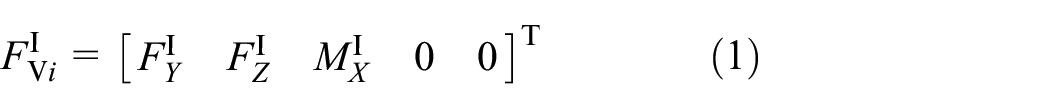


in which the superscript “I,”“II,” and “III” denote the wind forces on the car-body without wind barriers, into or out of wind barriers, and in wind barriers completely, respectively.
Due to the different aerodynamic coefficient of the train inside and outside the barrier the wind load on the train putting into and out of the barrier change suddenly. The process into and out of the wind barrier can be divided into five stages:
The train runs outside the wind barrier. In this stage the static wind forces on the car body don’t change with the time t including the side force, lift force, and rolling moment, so the wind forces are calculated on basis of the aerodynamic coefficients of the train on the bridge without wind barrier;
The train moves into the wind barrier. During this stage the front of the train passes the beginning section of the wind barrier until the rear is fully in the wind barrier, the static wind forces on the car body are linear change with time t including the side force, lift force, and rolling moment, however, the pitching moment and yawing moment are quadratic with time t;
The train runs inside the wind barrier. During this stage the rear of the train passes the beginning section of the wind barrier until the front arrives at the ending section of the wind barrier, the static wind forces on the car body don’t change with the time t including the side force, lift force and rolling moment which are closely related to the porosity of the wind barrier because of the sheltering effect, so these wind forces can be calculated on basis of the aerodynamic coefficients of the train on the bridge with wind barrier;
The train moves away from the wind barrier. During this stage the front of the car body passes the ending section of the wind barrier until the rear also passes the ending section of the wind barrier, the static wind forces on the car body are linear change with time t including the side force, lift force, and rolling moment, but the pitching moment and yawing moment are quadratic with time t;
The train runs outside the wind barrier. During this stage the train passes away from the barrier, the train runs outside the wind barrier, the static wind forces on the car body is the same as described in the stage 1.
The whole process of the train entering and leaving the wind barrier is shown in Figure 2 where l is the length of the wind barrier and lv is the vehicle length (l > lv). When the i-th vehicle of the train passes the wind barrier at a speed V, it goes through three stages, namely the train enters the barrier, runs in the barrier and moves out of the barrier.

Whole process of a train driving into, in and out of the barrier.
The calculated formulas of wind forces on the car-body can be found in detail in Zhang et al. Then the wind forces on the car-body during these five stages can be obtained. In addition, the fluctuating wind forces on the car-body can be also obtained similarly to the static wind forces.
Design for the transition section of wind barrier
Measures slowing sudden change of wind load
The sudden change of wind forces on the car-body occurs due to the presence of the wind barrier, which inevitably reduces the running safety of the train. The main reason of the sudden change of wind forces is the sudden change of the aerodynamic three-component coefficient of the train, especially the lateral aerodynamic coefficient. The relevant countermeasures can be taken to make the aerodynamic coefficient of the train change smoothly, that is, carrying out the specific design for the transition section of wind barrier. In this transition section, the height of the barrier is uniformly changed from zero to the designed maximum height h, and the porosity rate β of the barrier remains unchanged, and the length of the transition section is l1 (Figure 3). At this point, the aerodynamic coefficient of the train also changes steadily with the porosity rate, not change suddenly. Then quantitatively analyze the running safety of the train after applying this measure.

Side view of wind barrier with gradient height.
Change rule of three-component coefficients of train and bridge with wind barrier
It is very critical to obtain the aerodynamic three-component coefficient of the train and bridge with the different height of wind barriers on the bridge for the wind barrier design on the transition section. The change law of aerodynamic coefficients can be given on the basis of wind tunnel test which was carried out with a section-model in the wind tunnel laboratory of Beijing Jiaotong University. These aerodynamic coefficients of the train and bridge are defined by the following formulas:

in which CL(α) and CM(α) are the lift, and moment coefficients for the bridge and the vehicle when the wind attack angle is α, respectively, CD(α) is the drag coefficient of the bridge, CS(α) is called the side-force coefficient for the vehicle; FD(α), FS(α), FL(α), and M(α) indicate the measured drag forces, side-forces, lift forces and moment value with the wind attack angle α, respectively; H, B, and L represent the height, width and length of the bridge model or vehicle model, respectively; ρ is the air density; U is the oncoming wind velocity; and α is the attack angle of the wind flow. The directions and action points of aerodynamic forces on bridges and vehicles are plotted in Figure 4. The section-model of vehicle-bridge system with a single-side barrier is shown in Figure 5, and the scale is 1:32. The wind tunnel test model is designed as a vehicle-bridge combination with different wind barrier heights in order to consider the effect of wind barrier heights on vehicle and bridge aerodynamics, an the wind barrier heights are set to 0, 2, 3.5, and 5 m, but the porosity rate β of the barrier is a constant value 30%.
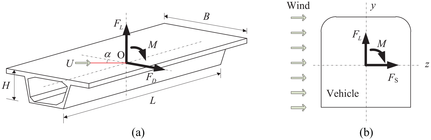
Direction and action points of aerodynamic forces on bridge and vehicle. (a) Bridge; (b) Vehicle.
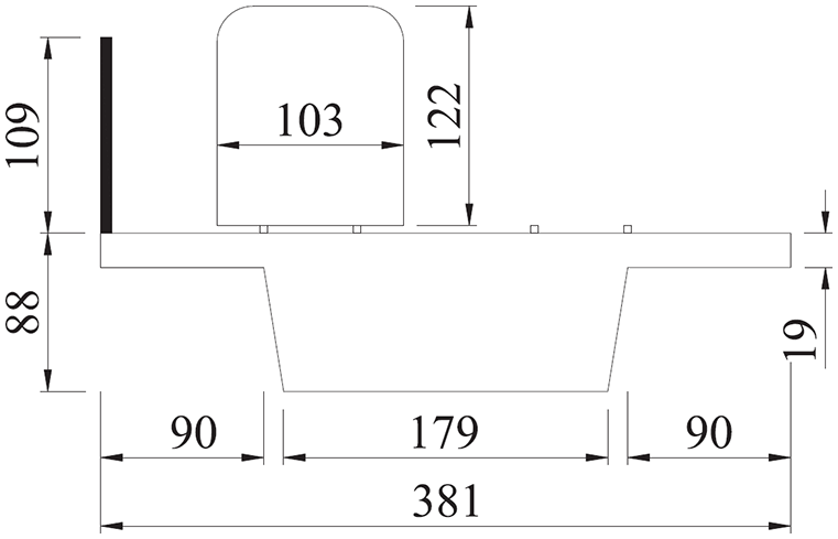
Scaled model of coupling system (Unit: mm).
The wind tunnel test results are shown in Figure 6 where the changing rules of the aerodynamic coefficients for the vehicle and bridge are plotted as a function of the height of the wind barrier when the porosity rate of wind barrier is equal to 30%. And it can also be found that the wind barrier height significantly affects the aerodynamic coefficient of the vehicle. When the height of wind barrier is increased from 0 to 3.5 m, the side force coefficient and the rolling moment coefficient of the vehicle are gradually reduced, especially the side force coefficient is more obvious. If the height of the wind barrier is 3.5 m, the side force coefficient is reduced to about 30% of that when the wind barrier is not installed. Nevertheless, the drag coefficient and the moment coefficient of the bridge increase slowly with the wind barrier height.

Change curve of aerodynamic coefficients of vehicle and bridge with wind barrier height h. (a) Vehicle and (b) Bridge.
Dynamic analysis model of wind-train-bridge system with wind barriers
Based on the existed model of the vehicle, bridge, and wind field, 21 the wind-train-bridge dynamic interaction analysis model is established considering the effect of the wind barrier. Since the stiffness of wind barrier is small relative to the bridge, and only the stand column of the wind barrier is connected to the bridge, the influence of the wind barrier on the bridge mode is ignored. Therefore, only the influence of the wind barrier on the wind force acting on the bridge and the vehicle is considered, and then the dynamic response of the coupled system is calculated.
The motion differential equations of train-bridge dynamic interaction system under wind load can be given:

in which the subscripts v and b indicate the train and bridge, respectively;
Case study
System input data
During the design of the new-built Lanzhou-Xinjiang high-speed railway, the self-written wind-train-bridge calculation program was used to calculate the evaluation indices of running safety of the train on the bridge considering the specific design of wind barrier in the transition section when the wind direction is normal to the motion of the vehicle at the level of the vehicle mass center.
The bridge is on the new Lanzhou-Xinjiang railway line, which consists of 12 × 32 m simply-supported box-girders with 12.2 m width and 2.82 m height, and the solid piers of 15 m height. The finite element model of the bridge shown in Figure 7 is established by the popular commercial software. The natural frequencies of the first 100 modes of the bridge are in the range of 1.54–30.2 Hz.

Finite element analysisi model of the 12-span bridge.
In the wind prone region of the Lanzhou-Xinjiang railway, the single-side 3.5 m height wind barrier is installed on the bridge, as shown in Figure 8. But there are two cases to set the wind barrier along the bridge: (1) the wind barrier with uniform height (the wind barrier height h = 3.5 m, the porosity rate β = 30%) is installed in partly section, shown in Figure 9(a) and (b); (2) the wind barrier with gradient height is installed in partly section, shown in Figure 9(c) and (d), in which L is the total length of the bridge, l is the total length of the wind barrier, l1 is the length of wind barrier in the transition section and ls is the distance from the bridgehead to the starting location of wind barrier. In this case, L, l, l1, and ls are 393.4, 250, 24, and 50 m, respectively.

Single-side wind barriers on the box-girder bridge (Unit: cm): (a) side view of 3.5 m single-side wind barrier and (b) elevation of 3.5 m height single-side wind barrier.

Arrangement of wind barriers on bridges: (a) partly section on the bridge with wind barrier, (b) side view of wind barrier with uniform height, (c) transition section on the bridge with wind barrier, and (d) side view of wind barrier with gradient height.
The train in the case study is the ICE train from Germany composed of eight cars, that is, 2×(3M+1T), in which M stands for the motor-car and T stands for the trailer-car. The length, height and width of every car are 24.775, 3.5, and 2.7 m, respectively. The average static axle load of a motor-car is 160 kN and of a trailer car is 146 kN. The other key parameters of this ICE train can be obtained in Xia et al.
21
The train moves on a straight track at a constant speed from left to right. In this case, the train speed V is equal to 250 km/h, and the mean wind velocity
The track irregularities are generated by numerical simulation through the harmonic synthetic method on basis of German PSD functions of track irregularities which are also recommended for China high-speed railway technical guidelines. 21 The length of the simulated irregularity is 2000 m, and the maximum amplitude is 8.65 mm in the lateral direction, 11.0 mm in the vertical direction and 0.0058 rad in the torsional direction, as shown in Figure 10. Then the fluctuating wind velocity time series are simulated according to the given PSD functions in the code in China 32 adopting the method in Ref. 28 The time-history curves of the fluctuating wind velocity at a point on the bridge is shown in Figure 11, and the average wind velocity at this time is 15 m/s.

Simulated rail irregularities in the case.

Simulated fluctuating wind velocity time-history curves.
Vehicle response and safety indices
According to the given input parameters and wind-vehicle-bridge interaction analysis model, the wind forces acting on the bridge and vehicle are calculated considering the wind barrier on the bridge with uniform height or gradient height. Then the whole process analysis of ICE high-speed train moving on the bridge with the wind barrier in the wind field for the above two cases are carried out. Thus the dynamic responses of the car-body and the evaluation indices of train running safety are given to evaluate the running performance of the train and passenger comfort, especially when the train enters and leaves the wind barrier.
The lateral and vertical accelerations of the car-body are the dynamic responses of primary interest for the comfort evaluation of the train. The evaluation indicators of train operation safety mainly include derailment coefficient, offload coefficient, the lateral wheel-rail force and overturning coefficient. Detailed definitions of these indicators can be found in Xia et al. 21 When these indicators are used, the bigger the indicator value is, the worse the operation condition for the train is.
Some results are given in Figures 12 to 17 such as the car-body acceleration and safety evaluation indicators of the train including two cases, that is, Case A (250 m wind barrier installing on the bridge with uniform height, as shown in Figure 9(a) and (b)) and Case B (250 m wind barrier installing on the bridge with gradient height, as shown in Figure 9(c) and (d)) when the train speed V is 250 km/h, and the mean wind velocity

Lateral acceleration time histories of the car: (a) motor-car (the third car) and (b) trailer-car (the fourth car).

Vertical acceleration time histories of the car: (a) motor-car (the third car) and (b) Trailer-car (the fourth car).

Derailment coefficient time histories of the car: (a) motor-car (the fourth wheelset of the third car) and (b) Trailer-car (the fourth wheelset of the fourth car).

Offload coefficient time histories of the car: (a) motor-car (the fourth wheelset of the third car) and (b) trailer-car (the fourth wheelset of the fourth car).

Lateral wheel-rail force time histories of the car: (a) motor-car (the fourth wheelset of the third car) and (b) trailer-car (the fourth wheelset of the fourth car).

Overturning coefficient time histories of the car: (a) motor-car (the third car) and (b) trailer-car (the fourth car).
It can be seen from Figure 12 that the lateral acceleration of the car-body suddenly increase when the train drives into the barrier with uniform height, the maximum lateral acceleration is 1.19 m/s2 for a motor-car, 1.18 m/s2 for a trailer-car. There is similar variation when the train drives out of the wind barrier with uniform height, and the maximum lateral acceleration is equal to 0.845 m/s2 for a motor-car, 0.978 m/s2 for a trailer-car. However, if the wind barrier is designed specially in the transition section such as Case B, the variation rage of the lateral acceleration of the car-body is smaller, and the maximum lateral acceleration is equal to 1.10 m/s2 for a motor-car, 1.12 m/s2 for a trailer-car when the train running into the wind barrier; 0.673 m/s2 for a motor-car, 0.682 m/s2 for a trailer-car when the train running out of the wind barrier. The sudden change of car-body lateral acceleration is the main reason of car swaying, so the counter measure in the transition section of wind barrier is very effective to reduce the car swaying.
Figure 13 gives time-history curves of the car-body vertical acceleration, as can be seen from this chart the maximum vertical acceleration is 1.08 m/s2 for a motor-car, 1.17 m/s2 for a trailer-car in Case A. But the value is 1.04 m/s2 for a motor-car, 1.06 m/s2 for a trailer-car in Case B. The car-body vertical acceleration don’t suddenly change when the train running into or out of the barrier. And there is little effect on the car-body vertical acceleration installing the wind barrier of gradual height on the bridge.
The evaluation indicators of train operation safety including the derailment coefficient, offload coefficient, and lateral wheel-rail force have no great change both Case A and Case B from Figures 14 to 16. And the derailment coefficient, offload coefficient and lateral wheel-rail force when the train is inside the protect region of wind barrier (250 m) are much less than when the train is outside, so the wind barrier can effectively reduce the derailment coefficient, offload coefficient and lateral wheel-rail force of the train to protect the operation safety of the train in wind field.
The overturning coefficient of the train that is another important index evaluating the crosswind safety of the train suddenly change when the train enters and leaves the wind barrier both Case A and Case B, but the variation amplitude is greater in Case A than in Case B. The overturning coefficient reaches the maximum value when the train is leaving the wind barrier, 0.492 for a motor-car and 0.438 for a trailer-car in Case A, 0.59 for a motor-car and 0.523 for a trailer-car in Case B. Thus, the special design of wind barrier obviously decrease the overturn factor. There is a decrease of approximately 17% in overturning factor of the motor-car and trailer-car if installing the wind barrier with gradient height on the bridge.
Conclusions
This paper researches the sudden change of wind forces on the car-body when a train enters or exits the wind barrier on the bridge called the transition section and the dynamic response and operation safety indicators of the train caused by the sudden changed wind force. Then the special design scheme of the wind barrier is proposed in the transition section. There are two cases, including the wind barrier with uniform height along the railway line and the wind barrier with gradient height, to get the change rule of the dynamic response and the effect of the special design for wind barrier in the transition section. Some conclusions are summarized as follows:
The car-body lateral acceleration suddenly increase when the train drives through the transition section. But the variation amplitude of the car-body lateral acceleration is much smaller considering the special design for wind barrier, in other words, the lateral acceleration will decrease if the wind barrier with gradient height is installed in transition section on the bridge. So the car swaying is reduced. And there is little effect on the car-body vertical acceleration in these two cases.
The derailment coefficient, offload coefficient and lateral wheel-rail force of the vehicle have no great change in these two cases. But it can be found that the wind barrier can effectively protect the running safety of the train through comparing these safety evaluation indices inside and outside the wind barrier.
The time history curves of overturning coefficient of the vehicle clearly indicate the adverse effect of sudden change of wind forces induced by wind barrier, which greatly increases the risk of the train overturning. However, the special design of the wind barrier in the transition section can effectively prevent the train from overturning.
Footnotes
Handling Editor: Chenhui Liang
Declaration of conflicting interests
The author(s) declared no potential conflicts of interest with respect to the research, authorship, and/or publication of this article.
Funding
The author(s) disclosed receipt of the following financial support for the research, authorship, and/or publication of this article: The research work in this paper was supported by the National Natural Science Foundation of China (Grant Nos. 51608087), Key-Area Research and Development Program of Guangdong Province in China (No. 2019B111106002), the Science and Technology Innovation Program of Hunan Province in China (No. 2021RC3016), and the Fundamental Research Funds for the Central Universities of China (No. 3132019349).