
Abstract
The current study reports a numerical analysis of a two-dimensional steady-state natural convection heat transfer from grooved heated cylinder for laminar flow regime. Two groove shapes are investigated in this work: circular and triangular groove. Simulations were carried out by varying the groove location, radius ratio f from 0.1 to 1, and the Rayleigh number over the range [103–106]. The thermal and dynamic behaviors are carefully analyzed and compared to the case of non-grooved cylinder (model 0). It is found that the heat transfer rate rises up with the increase of Rayleigh number. In addition, the groove locations φ = −90, and 80° provide the lowest heat transfer rate. A decrease of 9.4% in the heat transfer rate is detected for the case of triangular groove with f = 0.7 and Ra = 105. On the other hand, the highest heat transfer rate is provided at a position φ = −45° and 45° for f > 0.65. For these last groove locations, lower f present optimal configurations to accumulate heat on the cylinder. In fact, circular grooved cylinder with f = 0.1 decreases the heat loss by 9.3% and 12.4% for the locations φ = −45° and 45°, respectively compared to model 0. These results would be useful for engineering applications that are interested in the accumulation or transfer of heat through cylindrical ducts.
Introduction
Natural convection heat transfer in enclosures has long been a major necessity in many engineering applications, such as cooling electronic devices, heating spaces, solar heating, heat recovery applications, heat storage technology, etc. Despite its complexity, heat transfer by natural convection remains the most widely used solution for exchanging heat in the majority of industrial applications. Several research works were developed in this context to study natural convection heat transfer in enclosures with heated object(s) of different geometry embedded within. Different aspects were then conducted numerically as well as experimentally by changing the shape of the enclosure since it plays a very important role in the reduction or the increase of heat loss. Research works treated the cases of triangular,1–4 square,5–7 and arbitrary8,9 enclosures with various geometries of inner heated objects. In the other hand, the form of the inner heated surface has also an important effect on the heat transfer rate in the enclosure. In this context, particular interest was occurred to study natural convection heat transfer in enclosures containing heated cylinder due to their wide use in technological and engineering applications.10–17 Churchill and Chu 10 developed correlating equations of mean Nusselt number for the case of uniform heated cylinder in enclosure whose walls are maintained at a uniform temperature uniform. The correlations made are available for all Rayleigh and Prandtl Numbers. Cesini et al. 11 studied both numerically and experimentally the effect of confinement ratio of the rectangular enclosure on thermal and dynamic behavior in the cavity containing a horizontal heated cylinder for several Rayleigh number over the range from 1, 3.103 to 7, 5.104. The heat transfer rate increases well with the increase of Rayleigh number and reaches its maximum with small aspect ratio of the cavity. Mohammed et al. 12 studied numerically natural convection coupled to radiation in square cavity containing heated cylinder using the LBM method. The effect of radiation as well as the diameter of the heated cylinder on natural convection heat transfer were tested for different values of Rayleigh number. The increase of cylinder diameter leads to an increase in the thermal gradient and an extension of the flow over the entire cavity. In addition, in the presence of thermal radiation, temperature gradients are homogenized and the rate of heat transfer improves further. Angeli et al. 13 carried out correlations estimating the convective heat transfer rate in square enclosures for different diameter of the heated cylinder. The authors aim to determine the limit of stability for different Rayleigh numbers. They showed that the thermal aspect as well as the structure of the flow change considerably from one cylinder diameter to another. Similarly, they showed that the critical Rayleigh value varies from one diameter to another. Their results were in good agreement with those of shu et al. 14 In the same context, Sadeghipour and Razi 15 studied the convective heat transfer from horizontal cylinder situated between vertical walls. The authors determined an optimal wall spacing that maximizes the heat transfer rate for low Rayleigh numbers. The vertical position of the heated cylinder in the cavity was numerically explored.16,17 Kim et al. 16 showed that for Ra = 105 and 106, the cylinder position has no effect on the heat transfer rate in the cavity. However, Yoon et al. 17 found that the effect is pronounced when Ra = 107. The convective heat transfer was found to be dependent of the distance between the cylinder and the horizontal walls.
Furthermore, several research works have proved that the number of heated cylinders and their positions in the cavity have an important effect on the convective heat transfer rate.18–24 Corcione 18 studied natural convection heat transfer from a vertical array of isothermal cylinders. The author found that the bottom cylinder exchanges the same amount of heat of single cylinder. However, the heat transfer rate from downstream cylinders is affected by their locations in the array. The authors carried out correlations estimating the Nusselt number for every cylinder in the array, as well as for the whole cylinders array. Later, the author studied the case of pairs of tube arrays for Rayleigh numbers varying from 102 to 104. 19 Ismael et al. 20 studied numerically heat transfer by mixed convection in a vertically half partitioned cavity containing two rotating adiabatic cylinders. The vertical walls of the enclosure are differentially heated and the horizontal ones are kept adiabatic. As a function of the cylinder radius, it was found that the heat transfer rate is enhanced by 354.65% and 45.24% at Ra = 106 compared to that of Ra = 103 for cylinder radius of R = 0.1 and R = 0.4. Furthermore, increasing the Darcy number from 10-2 to 10−5 ameliorates the heat transfer rate by 235.1% for R = 0.1. Kitamura et al. 21 investigated experimentally the heat transfer from 10 cylinders arranged in vertical array with vertical spacing ranging from 3.6 mm to 150.6 mm. They showed that the plumes arising from the upper cylinder is laminar only when the cylinder spacing is smaller than 20.6 mm.
Brodnianská and Kotšmíd 22 studied the convective heat transfer from a tube array of 4 × 4 cylinders in basic, concave and convex configurations. The highest heat transfer rate was found at the convex configuration. Razzaghpanah and Sarunac 23 investigated numerically the free convection heat transfer from a vertical column containing 2 to 10 isothermal cylinders immersed in molten solar salt. They showed that previous correlations estimating the mean Nusselt number were not available for molten solar salt. They proposed then new correlations as a function of dimensionless spacing of cylinders and Rayleigh number over the range [104, 107].
Later, the authors treated the natural convection heat transfer from an array of 9 × 5 isothermal cylinders. 24 They showed that the heat transfer rate is affected by the longitudinal and the transverse cylinders spacing. The authors determined also an optimal spacing between cylinders that maximizes the heat transfer rate.
In fluid transport applications through pipelines, grooved pipes have shown a spectacular effect on the flow structure.25–27 Caliskan et al. 25 studied experimentally the effect of triangular groove on the flow characterisctics in shallow water for different groove location and different cylinder positions on vertical axe. They compared the flow structure to that of bare cylinder. They showed that the flow field is widely affected by the groove angle. The maximum Reynolds stress coefficient and turbulent kinetic energy were found with a grooved cylinder placed at the bottom wall of the enclosure (h = 0 mm) with a groove location a = 90°. Also Canpolat 26 controlled experimentally the unsteady flow structure behind rectangular grooved cylinder in shallow water for various groove locations and different cylinder height locations. The flow behavior was carefully analyzed and compared to the case of bare cylinder because the vortex forms changed according to the groove location. Tantekin et al. 27 made a comparison between rectangular grooved, square grooved and bare cylinder and they determined experimentally the highest and smallest drag coefficient, smallest wake region, smallest positive, and negative counter for the case of square and rectangular groove.
Grooved cylindrical pipes are widely used in fluid transport applications. Depending on the type of application, it is usually required to reduce heat losses through the surface of the grooved pipe to keep constant fluid temperature, or also to maximize the rate of cooling by natural convection in order to maintain colder temperature of the transported fluid.
According to the review of the literature developed, the majority of works that have studied natural convection heat transfer in cavities containing hot objects focused on the number of heat sources and their shape, the cavity shape, and its dimensions, etc. With regard to the grooved heat sources, the effects of several parameters on the dynamic behavior in the cavity were also carefully developed. However, the effect of the groove on heat transfer rate was not studied enough. Our aim in this paper is to develop a numerical investigation of natural convection heat transfer from grooved cylinder. Special attention is given to the impact of groove shape, and its location on thermal and dynamic behavior in the rectangular enclosure, as well as on the convective heat transfer rate. Results that will be presented in this paper may be very useful for various fluid transport applications in grooved cylindrical pipes that seek to maximize/minimize heat transfer rates.
Mathematical modeling
Problem formulation
The configuration under study consists of a rectangular air domain; assumed at cold temperature Tc; containing a grooved heated cylinder of radius R and infinite length. The heated cylinder is identified by its polar coordinates (R, θ), and its surface is kept at a hot temperature Th. The groove is obtained by subtracting a cylinder of radius R and located at a distance 2.R.f from the main cylinder. Two types of groove are considered in this work: circular groove (mode 1) depicted in Figure 1(a) and triangular groove (model 2) illustrated in Figure 1(b).

Schematic geometry of the problem: (a) circular grooved cylinder (model 1) and (b) triangular grooved cylinder (model 2).
Ten configurations are discussed in this work according to the type of grooves and their locations on the heated cylinder. In fact, five different locations are considered for each model of deformation. Note that the location of the groove is identified by the angle φ between its center and the horizontal axis (Ox). Tables 1 and 2 resume different configurations treated in this work.
Groove locations of model 1.

Groove locations of model 2.

Assumptions and governing equations
To simplify the numerical modeling of natural convection from heated grooved cylinder, we made some assumptions as follows:
The pipe is much longer than its diameter. This implies that the end effects can be neglected and the temperature and velocity are assumed to be bidirectional.
The flow field is steady, incompressible and the fluid is Newtonien.
Since the air velocity are low so the flow is assumed to be laminar.
The Prandtl number is equal to 0.71.
Based on these assumptions, the non-dimensional governing equations can be described in Cartesian- coordinates system as follows:
The continuity equation:

The momentum equations:
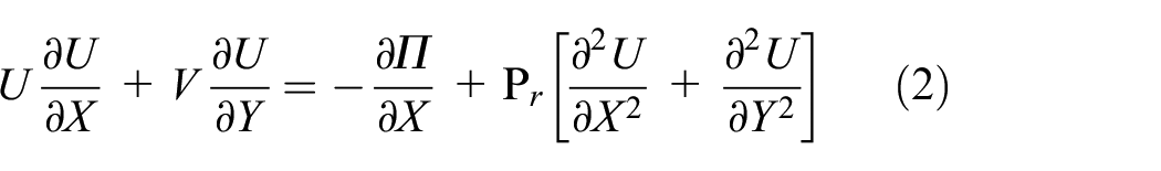
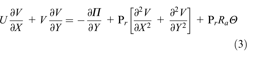
The energy equation:

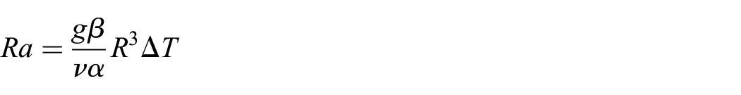
Where the non-dimensional groups used are as follows:
and the dimensionless numbers used are Prandtl number
The local convective heat transfer rate can be expressed in terms of local Nusselt number as follows:
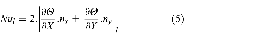
Where nx and ny are the components of the normal to the grooved surface
Finally, the average Nusselt number is obtained by averaging Equation (5) :
Where l indicates the position on the surface of the grooved cylinder, dl is the element length and L is the total length of the grooved surface.
Boundary conditions
a) For the cylinder: u = 0, T = Th
b) For the fluid domain:
On vertical and bottom sides: Inlet pressure condition: gauge pressure = 0, T = Tc
On top side: Outlet pressure condition: gauge pressure = 0,
Numerical procedure and validation
The numerical simulations were conducted using COMSOL Multiphysics® which is based on the finite element method. The main advantage of this engineering software is that it has many pre- and post- processing functions, allowing a flexible resolution of coupled multiphysics phenomena simultaneously and the understanding of complex scientific problems.
An adaptative triangular element mesh was used and it was locally refined near the deformed cylinder; as shown in Figure 2; where the velocity and temperature gradient seem to be very important.

Grid resolution of the problem.
A preliminary study of the mesh grid size was carried out to test the mesh dependence. So, the considered mesh consists of 27,751 domain elements and 675 boundary elements.
The validity of the numerical model was verified by comparing our numerical results with those of Corcione 19 for the case of non grooved cylinder which corresponds to the case f = 1 and noted model 0. The local distributions of dimensionless temperature and velocity are presented in Figure 3(a)) and b) for Ra = 104 and 105, respectively. In addition, values of local Nusselt number for Ra = 0.125.104 estimated by COMSOL were compared to those estimated by Corcione 19 for several azimuthal positions (Figure 4). The agreement is found to be good since our numerical study quantitatively matches well the data of previous numerical results.
Local distributions of dimensionless temperature and velocity for model 0 for: (a) Ra = 104 and (b) Ra = 105.

Comparison of the present study for the loca Nusselt number of model 0 with previous results of Corcione. 19
Results and discussions
Effect of groove location and Rayleigh number
Numerical simulations were performed for Pr = 0.71, and different values of Rayleigh number in the range between 103 and 106. We present in Figures 5 to 14 selected set of graphical results for Ra = 104 and 105 to provide an easy understanding of the parametric study developed.

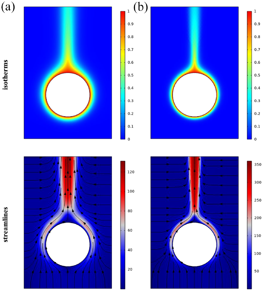
Isotherms, streamlines, and local Nusselt number for case (1, 1): f = 0.8, (a) Ra = 104, (b) Ra = 105.

Isotherms, streamlines, and local Nusselt number for case (2, 1): f = 0.8, (a) Ra = 104, (b) Ra = 105.

Isotherms, streamlines, and local Nusselt number for case (1, 2): f = 0.8, (a) Ra = 104, (b) Ra = 105.

Isotherms, streamlines, and local Nusselt number for case (2, 2): f = 0.8, (a) Ra = 104, (b) Ra = 105.

Isotherms, streamlines, and local Nusselt number for case (1, 3) : f = 0.8, (a) Ra = 104, (b) Ra = 105.

Isotherms, streamlines and local Nusselt number for case (2,3) : f = 0.8, (a) Ra = 104, (b) Ra = 105.

Isotherms, streamlines and local Nusselt number for case (1,4) : f = 0.8, (a) Ra = 104, (b) Ra = 105.

Isotherms, streamlines and local Nusselt number for case (2, 4) : f = 0.8, (a) Ra = 104, (b) Ra = 105.

Isotherms, streamlines and local Nusselt number for case (1,5) : f = 0.8, (a) Ra = 104, (b) Ra = 105.

Isotherms, streamlines, and local Nusselt number for case (2,5) : f = 0.8, (a) Ra = 104, (b) Ra = 105.
Local distributions
Φ = −90°
The local distributions of dimensionless temperature, dimensionless velocity and Nusselt number are depicted in Figures 5 and 6 for the cases (1, 1) and (2, 1) respectively for Ra = 104 and 105
The local distributions present symmetric profiles for Ra = 104, and 105. The first thing to remark is that; for Ra = 104; the thermal plume above the cylinder has not changed when deforming the geometry from model 0 to model 1 and model 2. So, the heat transfer rate in the upper part of the geometry is not affected by the groove. In addition, the thermal boundary layer thickness increases at the bottom of the cylinder with the circular groove. This fact causes a decrease in the temperature difference between the heated cylinder and the surrounding air, and leads to a decrease of the heat transfer rate in this region. Moreover, as it can be seen in Figure 5 the thinnest thermal boundary layer is located near the ends of the deformation. Then, the large temperature gradient results in an amelioration of the heat transfer rate in these parts compared to model 0.
For Ra = 105, as well as it is noticed in model 0, it is important to point out the decrease of the thermal boundary layers thickness around the cylinder, and the amelioration of the temperature gradient between the heated cylinder and the surrounding air. This amelioration is then noticed on the local distribution of Nusselt number, where the heat transfer rate is increased from 9 to 16 on the left and right sides of the cylinder. Furthermore, with the increase of Rayleigh number, the buoyancy forces are dominant. This leads to an amelioration of the air velocity on the ascending plume.
On the bottom of the cylinder, where the groove is located, the heat transfer rate is very low due to air stagnation and the accumulation of heat on the circular groove.
Figure 6 illustrates the distributions of dimensionless temperature, dimensionless velocity and local Nusselt number for the triangular grooved cylinder (model 2). For Ra = 104, Figure 6(a)), the rising plume strikes the grooved surface and splits into two loops and then rises along the hot cylinder surface. The thermal boundary layer is thick at the level of the groove which favors the accumulation of heat and the reduction of losses in this area.
When increasing the Rayleigh number to Ra = 105, the convective heat transfer is more dominant. The plume resistance becomes more important due to the decrease in its thickness, which generates higher heat transfer rate through the non-grooved surface of the cylinder. The plume rises on the top of the cylinder under the effect of the density difference. The heat loss in this part is then very low, which explains the low value of local Nusselt number above the cylinder
Compared to model 0, the dimensionless profiles are symmetric as well as model 0. In contrast, the air in the vicinity of the triangular groove is hotter than the rest of fluid. In fact, the plume becomes thicker inside the inner surface of the groove resulting in reduced heat loss from the inside surface of the groove. However, the thinnest thermal boundary layer is located on the ends of the deformation. The temperature gradient is then very important there, and the heat transfer rate is ameliorated compared to model 0.
Compared to model 1, the triangular grooved cylinder accumulates more heat in the vicinity of the groove, due to the decrease of the plume resistance in this region.
φ = −45°
Figure 7(a) and (b)) depicts the variations of dimensionless temperature, dimensionless velocity and local distribution of Nusselt number of case (1, 2) for Ra = 104, and Ra = 105. The local distributions above the cylinder have practically the same aspect of Figure 5 except for velocity fields which are more pronounced on the thermal plume. The heat transfer rate mounts up well with the increase of Rayleigh number and it is comparable to that of model 0 expect for the grooved surface. In fact, increasing the orientation angle of the groove surface from −90° to −45° helps air flow circulating due to density difference and transferring larger amount of heat by free convection. Moreover, it is particularly noticeable that the air velocity on the left end of the circular groove surface is practically zero. Therefore, the local distribution of Nusselt number is no longer symmetric, and the heat transfer through the left end is more pronounced than the amount transferred through the right end.
The local distributions of dimensionless temperature, dimensionless velocity, and Nusselt number corresponding to case (2, 2) are given in Figure 8 for Ra = 104 and 105.
It should be noticed here that the distributions are no longer symmetric. The air velocity increases well near the left and right sides of the cylinder, and it is more pronounced when increasing Rayleigh number to Ra = 105. The local heat transfer rate is then comparable to that of model 0 expect for the triangular grooved surface. In addition, we note the apparition of a fluid area at the grooved surface with quasi-immobile particles. The distribution of dimensionless temperature indicates that the hot air particles remain attached to wall especially on the middle of the triangular grooved surface where the thermal boundary layer reaches its maximum thickness. This explains the lower amount of heat transfer on the center of this area. Moreover, the accumulation of heat on the grooved surface decreases when increasing the groove orientation from φ = −90° to φ = −45° because of the amelioration of air flow intensity in this region.
φ = 0°
Figure 9 shows isotherms, streamlines and local distribution of Nusselt number corresponding to the case (1,3) for Ra = 104 and 105. It is worth to mention the improvement of the air velocity near the circular groove, and the deviation of the ascending air in the upper part of the domain. Besides, the heat transfer rate in the left part of the cylinder is ideally equal to that of model 0 whatever the Rayleigh number. The circular groove results in a decrease of the heat transfer rate compared to model 0. However, the amount of heat exchanged from the grooved surface is ameliorated compared to the case of φ = −45°. In fact, the larger the inclination of the groove, the larger the air velocity is leaving the grooved surface. This reflects the fact that, increasing the groove inclination facilitates the air flow in the vertical direction and ameliorates the heat loss on the grooved surface.
For the ends of the grooved surface, the air flow is accelerated and leads to an increase of the temperature gradient. The heat is then well conducted, which explains the higher values of local Nusselt number on the ends of the grooved surface. Note also that the amount of exchanged heat through the deformation is doubled when increasing Rayleigh from 104 to 105.
The dimensionless distributions of temperature, velocity and Nusselt number are shown in Figure 10 for case (2,3) for Ra = 104 and 105.
The streamlines pattern shows that the convective flow loses its symmetry. The air velocity increases especially near the upper end of the grooved surface due to its location.
As well as model 1, the heat transfer rate is perfectly equal to that of model 0 expect for the grooved region. Dimensionless temperature distribution shows that the thermal boundary layer developed on the grooved surface decreases in thickness when increasing Rayleigh number from 104 to 105. So the dead fluid zone (noticed on the middle of the triangular grooved surface) decreases considerably since the amelioration of flow intensity helps to drive the hot fluid particles upwards. This is clear on the evolution of the local Nusselt number which increases from 2.2 to 5 on center of the triangular groove.
ϕ = 45°
Figure 11 illustrates respectively local distributions of temperature, velocity and Nusselt number for the cases (1,4). It is worth to mention that the deviation of the thermal plume is more accentuated for the case φ = 45°. In fact, the flow intensity on the left part of the cylinder is higher than that of the right part where the groove is located.
The heat transfer rate is close to that of model 0 expect for the grooved part. In fact, locating the groove at φ = 45° results in the apparition of fluid area on the bottom part of the circular grooved surface with quasi-immobile particles. This causes a considerable drop of the heat transfer rate in this area as depicted in the local Nusselt number distribution.
Near the ends of the circular groove, the intensity of the air velocity increases well, which leads to an amelioration of the heat transfer rate in these parts compared to model 0.
The variation of dimensionless temperature, dimensionless velocity and local Nusselt number corresponding to cases (2,4a) and (2,4b) are presented in Figure 12(a) and (b)) for Ra = 104 and 105, respectively.
Compared to model 0, the triangular groove provides the same heat transfer rate expect for the grooved part. The dead fluid part on the grooved surface increases in the case of triangular groove. The accumulation of heat is then accentuated compared to the case of circular groove.
ϕ = 90°
Figure 13(a) and (b)) show local distributions of temperature, velocity and Nusselt number for model 1 for Ra = 104 and 105, respectively. Isotherms and streamlines take back symmetric profiles. It is also worth mentioning the appearance of two motionless rolls above the groove, which leads to an accumulation of heat inside the groove. This area is then full of quasi-immobile hot, so the heat transfer is almost zero. The vortex strength inside the groove decreases with Ra = 105, which leads to an enhancement of the heat transfer rate through the center of the groove surface. As well as for previous cases studied, the ends of the circular deformation provide the maximum heat transfer rate.
Local distributions of dimensionless temperature, dimensionless velocity and Nusselt number for the case (2, 5) are depicted in Figure 14(a) and (b)) for Ra = 104 and 105, respectively.
The two motionless rolls above the groove are also developed in the case of model 2. The heat transfer rate is equal to that of model 0 expect for the grooved part where it is zero at the center of the triangular groove and maximum through the ends.
Effect of groove location on the heat transfer rate
Figures 15 and 16 illustrate the evolution of average Nusselt number as a function of the groove location φ, for different radius ratios f of model 1 and model 2. For the two types of deformation studied, the heat transfer rate increases well with the increase of Rayleigh number. In addition, the effect of the groove location is more pronounced for Ra = 105 for both model 1 and model 2.

Effect of deformation location on the average Nusselt number for model 1.

Effect of deformation location on the average Nusselt number for model 2.
For Ra = 104, the average Nusselt number is practically constant when φ
Effect of Rayleigh number
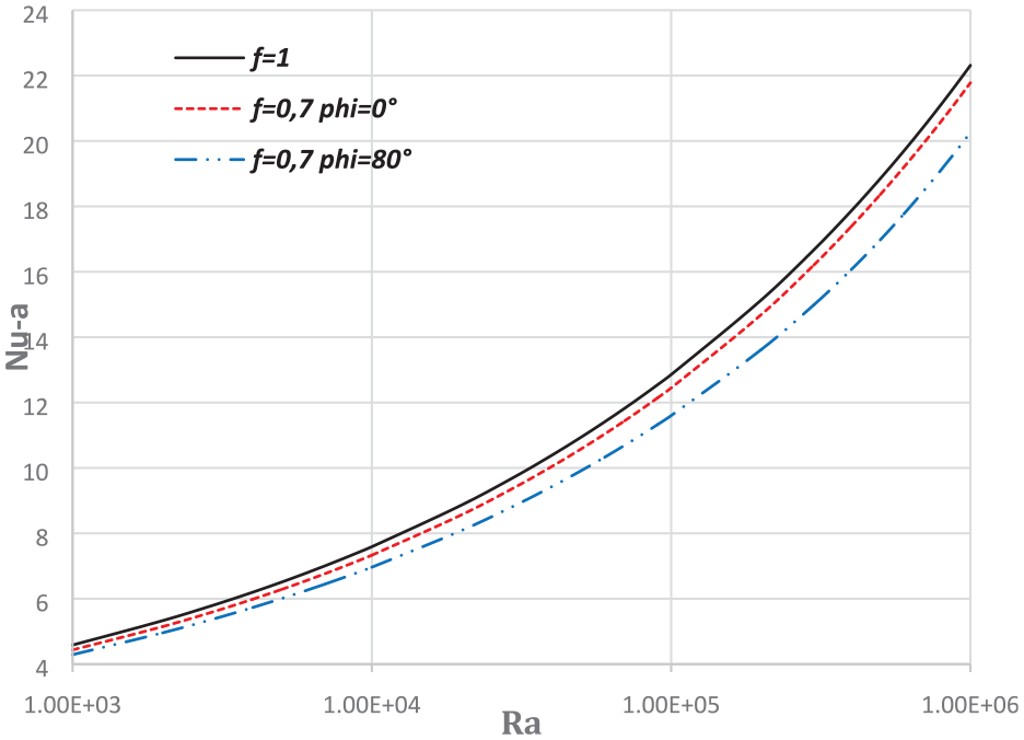
The effect of Rayleigh number on the average Nusselt number is displayed in Figures 17 and 18 for the two types of groove studied in this work. It should be noticed that the heat transfer rate increases well with the increase of Rayleigh number whatever the radius ratio, the shape and the location of the groove. For low Rayleigh number, the location and the radius ratio have no effect on the heat transfer rate since the transfer is entirely by conduction. However, the effect is more pronounced when increasing Rayleigh number. In fact, for f = 0.7 and Ra = 106 the amount of heat loss is decreased by 3.6% and 10.8%, respectively when using circular grooved pipe at the locations φ = 0° and φ = 80° instead of non-grooved pipe.

Effect of Rayleigh number on the average Nusselt number for model 1.
Effect of Rayleigh number on the average Nusselt number for model 1.
Effect of the radius ratio
Local distributions
f = 0.5
Figure 19 shows the variation of dimensionless temperature, dimensionless velocity and local Nusselt number for the case (1,4) for f = 0.5 and φ = 45°. The rising plume strikes the bottom part of the cylinder, so it is divided into two loops and then rises along the hot cylinder surface. The air velocity in the vicinity of the left part of the heated cylinder is higher than that near the right part due to the presence of the groove. So, the air flow rising above the cylinder is deviated. What is noteworthy here is that the circulation of air in the inner part of the groove is quite low (the air flow is quasi-immobile). So the heat is significantly accumulated in the vicinity of the circular groove especially for Ra = 104. Increasing the Rayleigh number to Ra = 105 leads to the appearance of a motionless circular roll in the bottom part of the groove, preventing the heat transfer in this area. The circular shape of the groove facilitates the air movement to the upside especially on the top region of the grooved surface. Thus, the heat transfer rate is enhanced only in this area.

Isotherms, streamlines and local Nusselt number for case (1,4): f = 0.5, (a) Ra = 104 and (b) Ra = 105.
The evolutions of local distributions of model 2 displayed in Figure 20 for the case f = 0.5 show that the temperature gradient is ameliorated when increasing Ra from 104 to 105. The circular roll that appears above the circular groove is no longer present in model 2. However, the air circulation is still low in the vicinity of the groove (especially at the center of the groove) due to the thickness of the thermal boundary layer. The heat transfer rate provided by model 1 is still higher than that of model 2.

Isotherms, streamlines and local Nusselt number for case (2, 4): f = 0.5, (a) Ra = 104 and (b) Ra = 105.
f = 0.7
Figure 21 depicts local distributions of temperature, velocity and heat transfer rate of model 1 for Ra = 104, and 105. The length of the groove decreases by increasing f. the transfer rate is then equal to that of model 0 over a larger area compared to the case f = 0.5. Concerning the grooved part of the cylinder, the heat transfer rate is improved compared to the case f = 0.5 since the immobile cell disappears while increasing f. For model 2, as shown in Figure 22 the center of the groove creates an important drop of the heat transfer rate compared to model 1. This is because of the lower circulation of air in the vicinity of the center of the triangular groove.

Isotherms, streamlines and local Nusselt number for case (1,4) : f = 0.7, (a) Ra = 104 and (b) Ra = 105.

Isotherms, streamlines and local Nusselt number for case (2,4) : f = 0.7, (a) Ra = 104 and (b) Ra = 105.
f = 0.9
As f increases, the profiles of the local distributions illustrated in Figures 23 and 24 tend toward those of model 0 since the length of the grooved surface decreases further. The thermal plume begins to return to a stable symmetric state since the flow intensity is practically the same on the left and right part of the heated cylinder. The heat transfer rate is then equal to that of model 0 over more than three quarters of the geometry. Furthermore, for the circular groove, the heat transfer rate reaches its maximum on the ends, and it is low on the rest of the deformation area because of low temperature gradient. Nevertheless, as illustrated in Figure 24 for model 2, the top end of the triangular groove exchanges less heat than that of the top end of the circular deformation. This can be related to the decrease of the temperature gradient at the center of the triangular groove, causing a drop of the heat transfer rate.

Isotherms, streamlines and local Nusselt number for case (1,4) : f = 0.9, (a) Ra = 104 and (b) Ra = 105.

Isotherms, streamlines and local Nusselt number for case (1,4) : f = 0.9, (a) Ra = 104 and (b) Ra = 105.
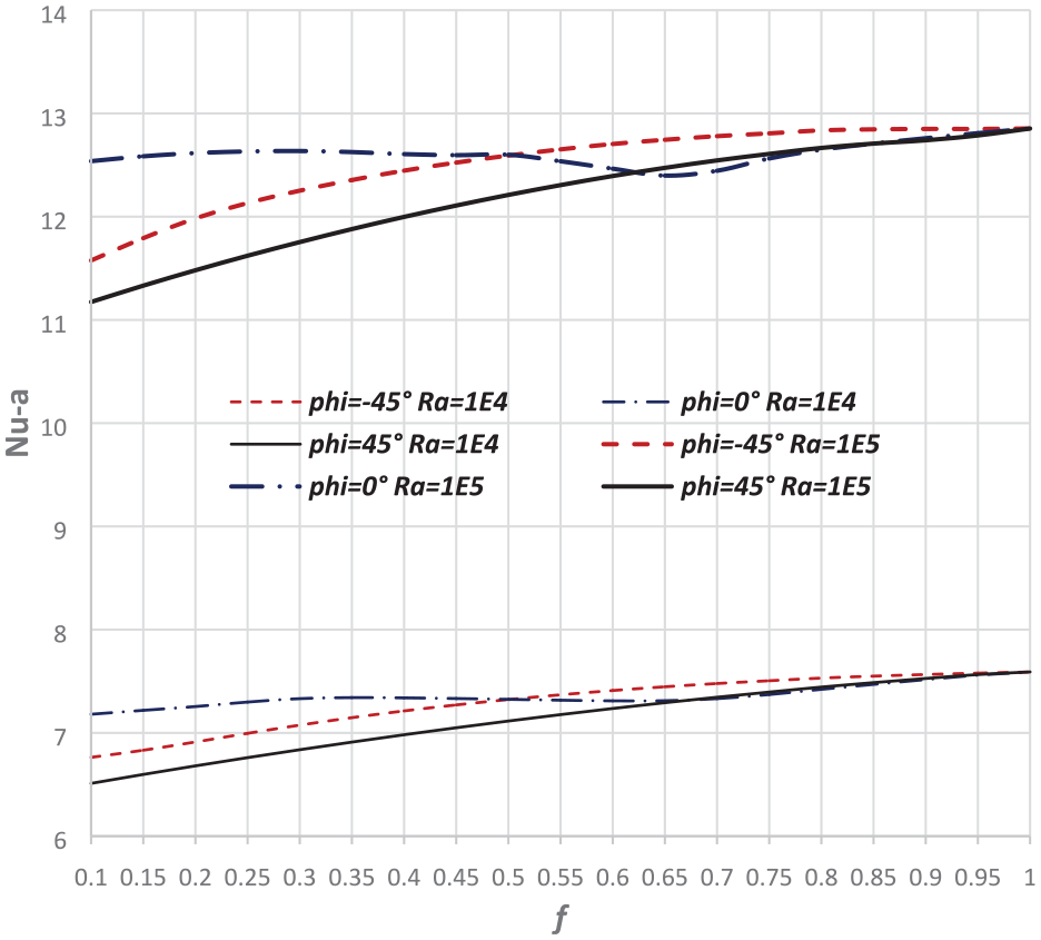
Effect of radius ratio on Nusselt number
The effect of radius ratio f on the heat transfer rate through the grooved cylinder is displayed in Figures 25 and 26 for the circular and triangular grooved respectively. Firstly, it is clear that the heat transfer rate increases well by increasing the radius ratio for φ = −45° and 45°. In fact, using a circular grooved cylinder with f = 0.1 instead of non-grooved cylinder can decrease the heat loss by 9.3% and 12.4% for the locations φ = −45° and 45°, respectively.

Effect of the radius ratio f on the average Nusselt number for model 1.
Effect of the radius ratio f on the average Nusselt number for model 2.
However, note the presence of small falling of average Nusselt number for the case of φ = 0° when f varies over the interval [0.5, 0.7]. Afterward, the average Nusselt number rises up by further increase of the radius ratio f. Furthermore, it is found that for low radius ratios (0.1 < f < 0.45), φ = 0° seems to be the best groove location that guarantees maximum heat transfer, and φ = 45° exchanges the lowest amount of heat for both circular and triangular deformation.
Conclusion
The effect of natural convection around grooved heated cylinder on heat transfer and fluid flow was numerically investigated in this work. Two types of groove were investigated: circular grooved and triangular grooved cylinder. In light of the obtained results, it is remarked that the flow pattern and the heat transfer rate are ameliorated with the increase of Rayleigh number for the two groove shapes studied. In addition, it is obvious to conclude that the groove locations φ = −90, and 80° provide the lowest amount of heat transfer for all radios ratio, Rayleigh number and groove shape studied in this work. For the case of triangular groove with f = 0.7 and Ra = 105, it was found that these locations provide a decrease of 9.4% in the amount of heat transferred compared to that of non-grooved cylinder. On the other hand, the highest heat transfer rate is provided at a position φ = −45° and 45° for f > 0.65. For the last groove locations, lower radius ratios present optimal configurations to minimize the heat transfer rate from the heated cylinder.
Finally, it would be interesting to explore the natural convection from an array of grooved cylinders. Evaluating the effect of grooved cylinder number, their longitudinal and transverse spacing on the heat transfer and fluid flow structure would be also important.
Footnotes
Appendix
Handling Editor: Chenhui Liang
Declaration of conflicting interests
The author(s) declared no potential conflicts of interest with respect to the research, authorship, and/or publication of this article.
Funding
The author(s) received no financial support for the research, authorship, and/or publication of this article.