
Abstract
Motion planners for autonomous driving improve traffic safety through collision-free motion generation along the path. However, conventional motion planners render passengers uncomfortable as a result of jerky motion. To overcome this, we propose a model predictive control (MPC) based motion planner that not only ensures safety but also improves driving comfort. The proposed planner generates path tracking and collision-free maneuvers to ensure safety, and improve driving comfort by minimizing acceleration and jerk. Collision-free maneuvers include vehicle following and overtaking. The target speed is determined by comprehensively considering path tracking performance improvement and whether overtaking is possible. The speed of the vehicle is controlled by considering longitudinal acceleration and jerk minimization. The steering command is determined by considering both path tracking error reduction, and lateral acceleration and jerk minimization. In cases where vehicle overtaking is required and during high-speed driving conditions, the consideration of lateral acceleration and jerk minimization increases to improve driving comfort. The proposed planner is formulated as a convex optimization problem. The effectiveness of the proposed planner was evaluated in path tracking and collision avoidance simulations. The simulation results confirm that the proposed planner ensures vehicle safety through lane keeping and collision avoidance, and improves driving comfort.
Keywords
Introduction
Motion planning algorithms are essential elements in the field of autonomous driving, as well as the fields of mobile robots and manipulators. In particular, autonomous driving has been the subject of attention in the past decade as a key to solving human error, 1 which accounts for 94% of all traffic accidents. Autonomous vehicles drive with collision-free motion along a path generated by the motion planning algorithm. The most popular motion planning algorithms in the field of autonomous driving are adaptive cruise control (ACC) 2 and lane keeping assist system (LKAS). 3 ACC is a function that maintains distance and speed to prevent collisions between a driving vehicle and a preceding vehicle and has reduced traffic accident fatalities by approximately 9%. 2 LKAS is a system that assists steering wheel control such that the vehicle does not deviate from the driving lane and is expected to prevent lane departure accidents by up to 66.5%. 3 The motion planning algorithm applied to autonomous driving has improved overall traffic safety, but unfortunately it has provided discomfort to some drivers and passengers.
The discomfort of the driver or passenger is caused by jerky motion, such as a sudden stop for autonomous vehicles to avoid collisions and a rapid acceleration for speed tracking. Some passengers of Tesla vehicles have complained about the discomfort caused by accelerating and decelerating motion while using Autopilot. 4 Additionally, sudden changes in steering are also factors that cause motion sickness and discomfort in passengers.5,6 The frequency of vehicle jerk increases because of a congested road environment or the aggressive movement of surrounding vehicles.7,8 Therefore, in order for a vehicle to minimize jerk, a smooth driving motion must be generated, considering various constraints that occur while driving.
Model predictive control (MPC) is a representative motion planning algorithm that generates optimal motion while considering various constraints. MPC determines the optimal control signal based on the control system’s future behavior prediction and constraints. 9 MPC-based motion plannings are divided into hierarchical approach and direct approach. The hierarchical approach creates a collision-free local path and determines the desired control input for path tracking. Local paths are generated based on path planning algorithms such as A*, 10 dynamic programing, 11 parametric curves,12–14 artificial potential field.15,16 Here, since path planning algorithms do not consider the motion constraints of the vehicle, an impossible path may be created. In the hierarchical approach, an impossible path leads to the generation of the desired motion with degraded tracking performance. On the other hand, the direct approach determines the desired motion without creating a collision-free local path. Therefore, the direct approach has advantages in the process of determining the desired motion, compared with the hierarchical approach.
In this paper, we propose an MPC-based motion planning algorithm that minimizes jerk without collision by utilizing a direct approach. The proposed algorithm plans motions using convex optimization to quickly find feasible control commands. Through this process, we create optimal maneuvers that include both vehicle following and overtaking. The generated maneuver allows the vehicle to be provided with minimal jerk and collision freedom. Therefore, the proposed algorithm ensures driving safety through collision-free motion and improves the driving comfort of passengers through jerk minimization. This paper is organized as follows: Section 2 presents a review of the existing MPC-based motion planning algorithms. Our vehicle motion model is introduced in Section 3. In Section 4, we discuss the constraints for creating control commands. In Section 5, we design a cost function for motion planning. The calculation of the target speed required for cost function formulation is described in Section 6. The proposed algorithm is evaluated in Section 7. Finally, Section 8 presents the conclusions of the study.
Related works
To ensure safety in complex driving environments, several driving strategies for collision avoidance have been used, including vehicle following, 17 overtaking, 18 emergency braking, 19 and evasive steering. 20 However, driving strategies that involve rapid motion changes significantly increase acceleration and jerk, making passengers uncomfortable. In addition, a sudden change in motion can cause accidents between a driving vehicle and adjacent vehicles. 21 Therefore, a new driving strategy is required to improve driving comfort while ensuring driving safety. A representative approach to consider driving safety and comfort is to use vehicle following or overtaking.
ACC is a representative technology for vehicle following. The latest ACC-based approaches are MPC-based motion planners that consider driving comfort as well. Gabalawy et al. 17 limited the longitudinal acceleration and jerk ranges to [−3 m/s2, 5 m/s2] and [−5 m/s3, 5 m/s3], respectively, to ensure driving comfort. The proposed motion planner converges to the desired distance and speed without exceeding the maximum acceleration by setting the acceleration and jerk boundary constraints. However, the proposed method has the disadvantage of using constant cost weights. Cost weights are parameters that determine the extent to which the motion planner considers driving safety and driving comfort. If driving comfort has a much greater weight than driving safety, the motion planner generates motion that stops gradually to maintain driving comfort in a situation where a sudden stop is required. In this case, the vehicle cannot stop, resulting in an accident. To address this problem, methods to adjust the cost weights between driving comfort and driving safety according to driving conditions in real time have been proposed.22,23 The proposed methods reset the cost weights based on the distance to the leading vehicle and the relative speed. If the leading vehicle is closer than the desired distance and the ego vehicle is faster, the distance and speed control weights are increased. Conversely, if the leading vehicle is farther than the desired distance, the acceleration control weight is increased. As a result, it is possible to converge more quickly to the desired distance and the target speed in a scenario where the leading vehicle that the ego vehicle follows suddenly changes. Furthermore, the driving comfort was improved by up to 63.26%. However, the actual road environment requires not only acceleration, but also various motions that require steering control such as left turns, right turns, and lane changes. Since the motion planner that considers only the vehicle following strategy generates only longitudinal motion without considering steering, there is a limit to its use in a real road environment.
An overtaking strategy wherein steering is considered generates a swerving maneuver that passes the leading vehicle in the same lane. Wang et al. 24 proposed an MPC-based motion planner that avoids obstacles near the global path with only steering control at the current speed. However, the proposed motion planner sets the driving speed of the ego vehicle as a constant. Therefore, as the steering angle increases, the lateral acceleration and jerk increase significantly, reducing the driving comfort. Gutjahr et al. 25 used a speed profile rather than a constant speed in the calculation of steering control commands to improve driving comfort. In addition, the range of vehicle curvature is limited based on the vehicle’s maximum physical steering angle and the conditions to maintain wheel traction at a given speed profile. However, the proposed method is dependent on a predetermined speed profile. Thus, if an incorrect speed profile is provided, the range of acceptable steering angles is reduced and the path tracking performance is degraded. Werling and Liccardo 26 proposed a motion planner that determines the speed and steering angle together. The proposed motion planner sets the acceleration constraint such that the vector sum of the longitudinal and lateral accelerations enters the traction circle representing the range at which the tire grip is maintained. However, because of the nonlinear vehicle model, the MPC formulation becomes non-convex, and the calculation of the feasible solution is generally slow compared with the planner in the form of a convex optimization problem. 27 Dixit et al. 18 and Taherian et al. 28 proposed a method of formulating the overtaking problem with convex optimization. The proposed planners use a linearized vehicle model and set the collision-free space as a convex region. Here, a collision-free space is set using a ramp barrier to guide the vehicle to the adjacent lane. However, ramp barriers limit the maximum longitudinal distance that a vehicle can move, causing unnecessary deceleration while moving into an adjacent lane. On the other hand, Ammour et al. 29 used a sigmoid barrier instead of a ramp barrier. Through the sigmoid barrier, the width of the entire road gradually decreases by one lane when a leading vehicle is detected. As a result, unnecessary deceleration caused by the ramp barrier-based approach was improved. However, motion planners using the overtaking strategy require a space where overtaking motion is possible, and there is a limit that does not consider vehicle following.
To overcome the limitations of using a single strategy, motion planners using both vehicle following and overtaking strategies have been proposed. Karlsson et al. 30 applied two different MPCs to perform both vehicle following and overtaking. After that, for each trajectory, the cost is calculated for driving comfort, path tracking error, and avoiding frequent changes in driving strategy, and only the trajectory with lowest overall cost is executed. However, the proposed method has a disadvantage of increasing the computation load because two MPCs need to be operated every iteration. Liu et al. 31 proposed a planner that can perform both single-lane change and vehicle tracking using one MPC framework. However, because of the vehicle model and collision-free constraints, the proposed planner is formulated as a non-convex optimization. According to the paper, 31 it is possible to fail to find a feasible solution. Franco and Santos 32 used a behavior planning flowchart to predetermine driving strategies. Subsequently, the constraints corresponding to the determined driving strategy were formulated. Through this process, the proposed planner allows both collision avoidance strategies while maintaining convex optimization. However, the proposed method does not consider acceleration and jerk, and it may create uncomfortable driving motions. Lattarulo and Pérez Rastelli 33 limited the range of longitudinal acceleration and jerk, and lateral acceleration to improve driving comfort. However, the proposed method only considers the minimization of path tracking error and speed error when planning motion. Thus, the proposed method plans the motion with given maximum acceleration and jerk to quickly reduce the two errors. Therefore, as the range of acceptable acceleration and jerk increases, it may cause motion with greater acceleration. However, acceleration and jerk affect driving comfort. Therefore, a safe and comfortable motion planning is required, considering not only collision avoidance and path tracking error reduction, but also acceleration and jerk reduction of the vehicle.
We propose a new motion planner that ensures safety and considers acceleration and jerk. The proposed motion planner integrates the target speed determination process and MPC. The target speed is updated in real time in consideration of the improvement of the path tracking performance in the curved section and whether overtaking is possible. This target speed determination allows the proposed motion planner to be formulated as a convex optimization problem. Once the target speed is determined, the proposed planner generates control commands to ensure safety and improve driving comfort in the motion optimization phase. A speed control command is generated to slowly converge to the target speed using cost terms that minimize longitudinal acceleration and jerk. Additionally, the steering control command is generated with consideration of minimizing path tracking error and the lateral acceleration and jerk. Here, in order to consider that the lateral acceleration and jerk increase as the speed increases during steering action, we used lateral motion cost weights that change according to the speed. In addition, we propose a cost function that creates a smooth steering control command in maneuver generation for obstacle overtaking.
Vehicle modeling
We aim to plan the collision-free motions that can actually be operated on vehicles. For this, it is necessary to consider the vehicle motion characteristics when planning the motions. To ensure the kinematic feasibility, we used a kinematics vehicle model in this work.
Kinematic vehicle model
To drive safely without colliding with road infrastructure in a structured environment, it is desirable to follow a given reference path (or global path) as possible. We model the vehicle movement along a given reference path. Considering that the tracking error consists of lateral error and orientation error, the lateral deviation, vehicle orientation, and path orientation are modeled as state variables to calculate these two tracking error components.
Moreover, to improve driving comfort, it is also necessary to consider minimizing acceleration and its derivative (jerk) when planning motion. The acceleration applied to non-slip vehicle can be expressed as the sum of the longitudinal acceleration and the centripetal acceleration, which is proportional to the curvature and velocity. Therefore, the curvature, speed, and longitudinal acceleration are also modeled as state variables. Referring to the paper,
25
the geometric relations between the vehicle and a given reference path can be expressed as shown in Figure 1, where


Kinematic vehicle model with respect to the reference path.
where
Linearization
Due to the trigonometric terms and fractional form in (1), the vehicle model is nonlinear. This can increase the complexity of calculating the future vehicle states. To simplify the model, linearization is performed on the vehicle model around the operating point. In this work, the operating point is selected based on the situation wherein a vehicle with current speed

If the vehicle drives near the operating point, the system can be linearized as in (3).

where

Discrete-time linearized vehicle model
Calculating future vehicle states over several seconds in the continuous-time domain can result in computational burden. To reduce the computational load, the continuous-time linear system is approximated by the discrete-time linear system. In this process, we assume that the system matrix

Finally, the discrete-time linearized vehicle model can be described as in (5) for

Considering that the external signal
System constraints
For safety, it is essential to drive without collisions with the surrounding obstacles. Depending on the presence of obstacles, it is sometimes necessary to plan motion such that the vehicle moves within a confined space. Furthermore, it is preferred to plan motion with consideration of the range in which the vehicle can actually operate. In this section, we formulate various constraints for each time step to avoid obstacles with feasible motions.
Representation of lateral displacement for collision avoidance
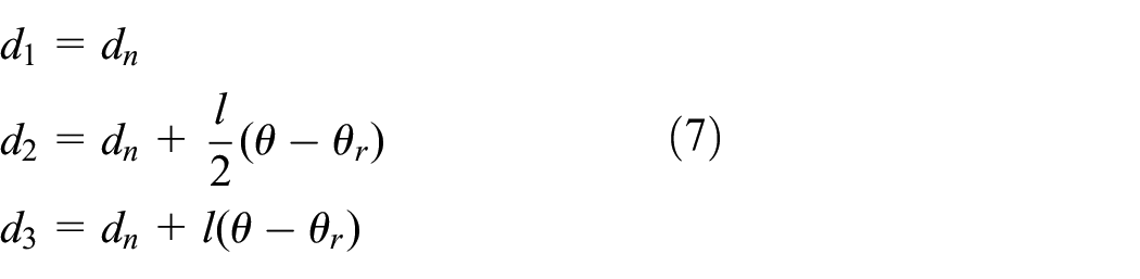
To define the constraints for collision avoidance, several lateral displacements are defined in this section. If unexpected obstacles exist near the global path, a maneuver to avoid collision with them is required for safety. Assuming multiple lanes exist, one way to create a collision avoidance maneuver in such situations is to induce the vehicle to move toward a collision-free lane by temporarily limiting lateral movement. To express this lateral range restriction, a displacement in the normal direction between the reference path and several points on the ego vehicle can be considered as outputs (see Figure 2). In this work, the deviations of the rear axle center, midpoint, and front axle center are formulated by (6).


Visualization of lateral displacements with respect to the reference path.
where
Lateral deviation constraints
Due to static and dynamic obstacles in the driving environment, the lateral position of the vehicle is limited. This can be expressed as a range wherein the circles that approximate the ego vehicle body can move in the lateral direction without colliding with the road boundaries and obstacles, as in the paper.
25
Each radius of collision-free circle is user-defined value, and we set the radius to cover the ego vehicle body with a little margin in this work. Figure 3 illustrates the lateral deviation constraints, which depend on the surrounding obstacles. The lateral deviation constraints can be formulated by (8), where

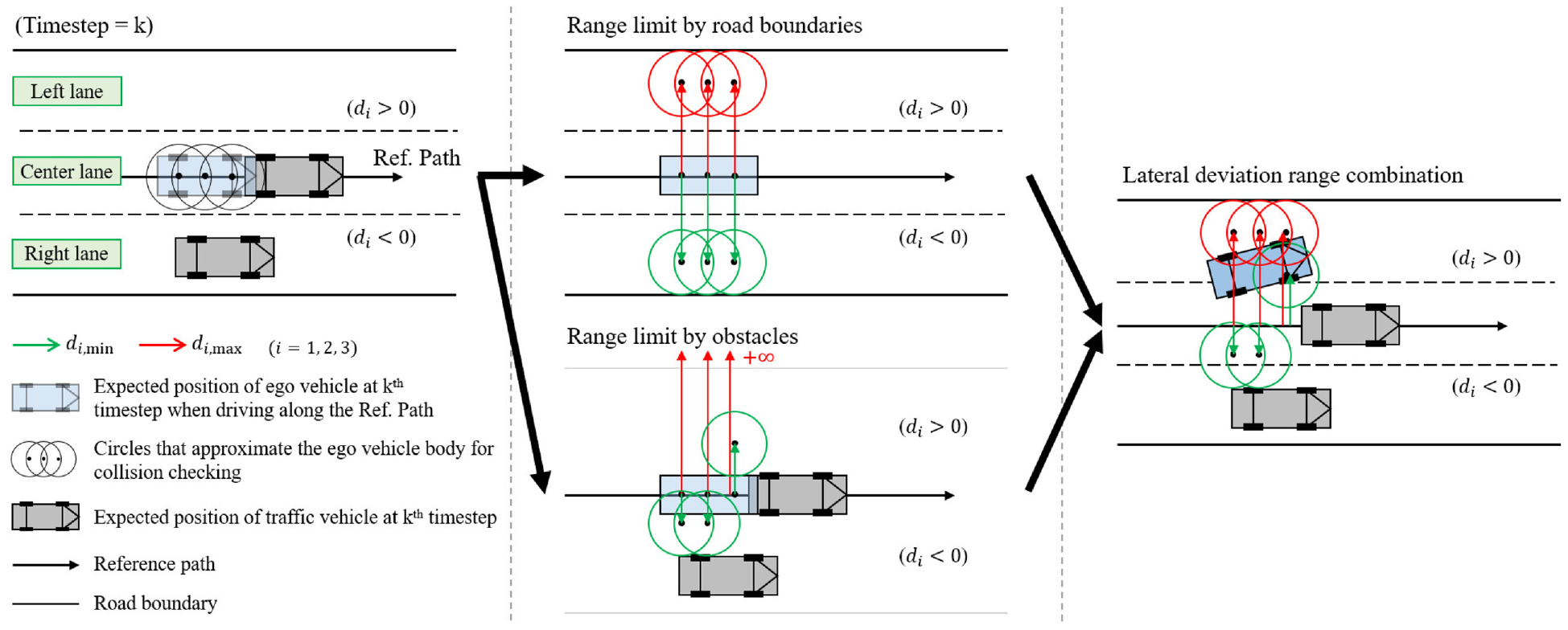
Visualization of the lateral deviation constraints. The red and green arrows indicate the deviation limits that the circles approximating the ego vehicle can move to the left and right from the reference path, respectively.
The process of determining the upper and lower limits of lateral deviation for each time step is as follows. For simplicity, we assume that all detected traffic vehicles drive at their current speeds constantly, and maintain their current lanes for all prediction horizon
In some cases, all lanes may be blocked by several leading vehicles. In this case,
Motion limits
Most vehicles have a limited range of steering angle and actuator input power. Thus, the control inputs and the vehicle curvature are bounded for all time steps. In addition, the vehicle must not exceed the maximum speed if there is a speed limit on the road. These constraints can be formulated as in (9).

Cost function
Lane departure prevention is essential to ensure safety. Therefore, it is important to follow the given path as well as possible. Conversely, if the vehicle’s acceleration and jerk increase, the vehicle may not only lose stability, but also become far from comfortable driving. Thus, it is also necessary to consider motion smoothness. In this section, the cost function is designed to determine the optimal motion sequence considering both the path tracking performance and smoothness.
Cost function design
Our goal is to generate a vehicle control input sequence that follows the reference path but has a comfortable motion. First, to consider reducing the tracking error, we used the following three terms for cost calculation.

where
On the other hand, a smooth and comfortable maneuver can be obtained by minimizing the force applied to the vehicle and its changes. This is equivalent to reducing the vehicle’s acceleration and jerk. The acceleration applied to the vehicle can be decomposed into longitudinal and centripetal accelerations if the vehicle does not slip. Considering that the centripetal acceleration is proportional to the curvature, a comfortable motion can be obtained by minimizing the curvature and longitudinal acceleration of the vehicle and their derivatives (i.e. control inputs). For this reason, these state values and control inputs are used in the cost calculation to consider driving comfort as follows.
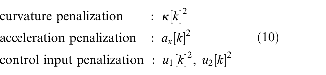
Intuitively, there is a trade-off between path tracking performance and comfortable driving. Based on this trade-off relationship, we designed the cost function in a quadratic form using all the cost terms mentioned above.
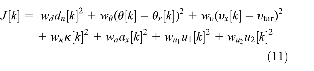
where

where
Variable weights for smooth lateral motion
The conventional method for setting the cost weights is to render all weights constant. If all weights are set to a constant, motions with the same driving style are planned in any driving situation. However, there is a limit to achieving both comfortable motion and path tracking performance improvement with a single driving style. In detail, it is always necessary to consider reducing the path tracking error such that lane departure does not occur for safety. Conversely, when the vehicle runs at a high speed, the importance of comfortable motion cannot be ignored because the driving comfort decreases as the centrifugal force increases. To address this problem,

where
Lateral error cost weight for smooth overtaking
When overtaking a leading vehicle on the reference path, the ego vehicle needs to move temporarily toward the adjacent lane. For comfortable driving, it is desirable to plan a motion that gradually changes lanes. However, it is difficult to generate comfortable motion in the form of the cost function (11) because lateral error cost becomes dominant in the overtaking scenario. Figure 4 shows the cost calculation and the expected vehicle trajectory in an overtaking situation when using the cost function (11) as it is.
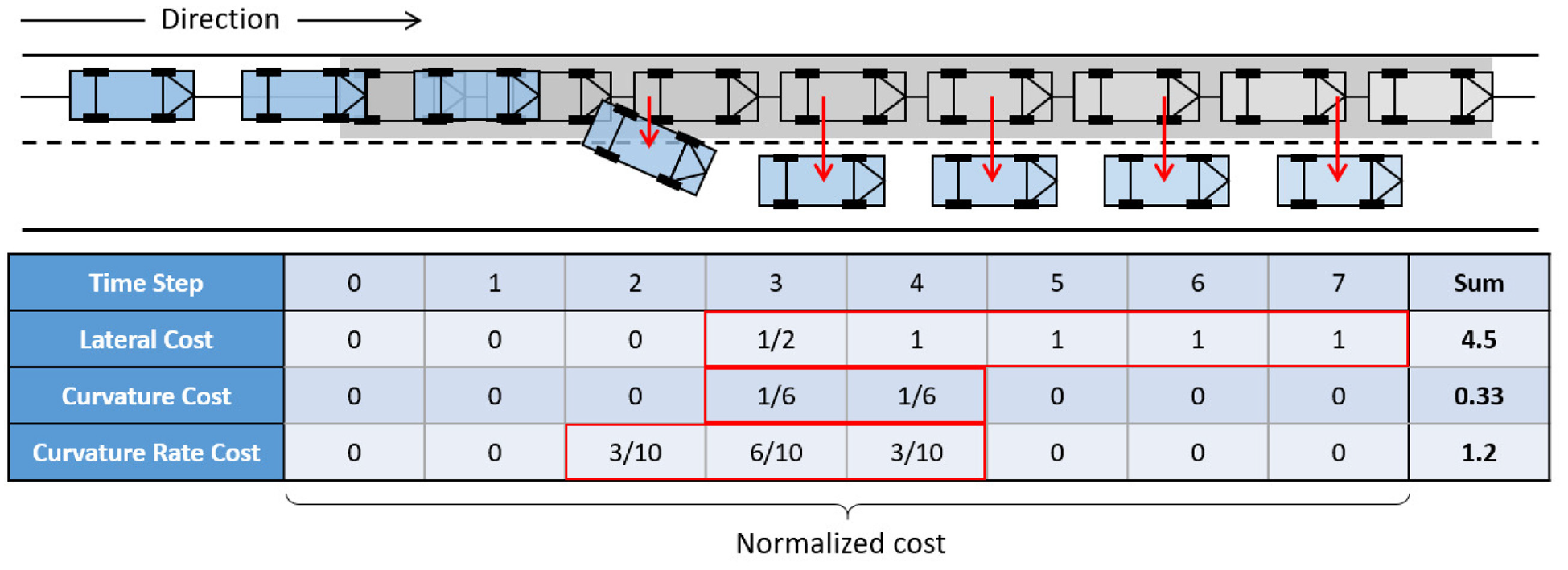
Cost for each time step and expected ego vehicle trajectory in overtaking scenario. The ego vehicle and leading vehicle are indicated by blue box and gray box, respectively.
As shown in Figure 4, when creating an overtaking maneuver, the steering action is only needed while moving the vehicle into the next lane, so the curvature and lateral control input costs are only increased while changing the steering. On the other hand, since the lateral error persists after moving to the next lane, the lateral error cost is accumulated until the last time step. That is, most of the total cost is the lateral error cost. Thus, to reduce the overall cost, a motion sequence that minimizes the lateral error cost is planned. Such a motion sequence forms the ego vehicle’s trajectory wherein the vehicle makes a sudden lane change just before colliding with the leading vehicle. Clearly, a sudden steering action is far from comfortable motion. To address this problem, we reduce the cumulative effect of lateral error cost by dividing the lateral error cost weight

Note that the reduced lateral error cost weight
Target speed calculation
As mentioned in Section 4.2, it is sometimes possible that all lanes are temporarily blocked by several leading vehicles. In this case, deceleration is more effective for avoiding collisions than trying to overtake. Also, to render the predicted movement of the kinematic vehicle model more accurate in a curved section, sufficient deceleration is required to reduce the dynamic effect, which can help to improve the path tracking performance in a high-curvature section. To achieve these two goals simultaneously, we calculate two target speed candidates for each purpose, and determine the final target speed by selecting one of them.
Non-side slip condition
The kinematic vehicle model describes its motion without considering the effect of the force. If the lateral motion resulting from the dynamic effect increases, the difference between the predicted motion calculated by the kinematic model and the actual driving maneuver might increase. Therefore, to reduce the difference between them, it is desirable to reduce the additional movement caused by side slip as much as possible. According to Park et al., 34 the non-side slip condition is given by the relationship between the curvature and speed of the vehicle as in (15).

where

Calculation of target speed
As the first process of calculating

If the calculation result of (16) exceeds the road limit speed
Vehicle following
If one or more obstacles are detected in each lane, including both forward and backward, driving at the speed of the leading vehicle until a free lane is created is more appropriate for safety, rather than trying to change the lane excessively. When performing vehicle following, it is necessary to drive at a sufficient distance to prevent collision, even if the speed of the leading vehicle changes. To accomplish this, we calculate the second target speed candidate by considering both the relative speed of the leading vehicle and the desired time gap.
First, the desired relative speed for vehicle following is 0, which is equivalent to setting the target speed of the ego vehicle as the leading vehicle speed. Through this, the speed error of the ego vehicle

where
Next, the speed at which the ego vehicle travels to have a predefined time gap

Through this, the speed error of the ego vehicle

Finally, to reduce both speed errors, we set a second target speed candidate

Meanwhile, it is not necessary to generate a vehicle following maneuver if the leading vehicles are too far (for instance, out of the sensor detection range), or if a free lane exists. In this case,
Target speed determination
In this step, the target speed is finally determined such that both the non-side slip condition and vehicle following are satisfied. Each target speed candidate corresponds to the “maximum” speed that satisfies the given condition within the range of the road speed limit. In

This target speed
Experiments
This section presents the simulation results for the proposed method. The performance was evaluated in terms of path tracking performance, acceleration, jerk in various curvatures, and collision avoidance ability.
Simulation setup
Our proposed planner was implemented in MATLAB, and the Gurobi Optimizer was used to solve the quadratic programing. Additionally, we used IPG CarMaker 35 as a vehicle simulator to evaluate the performance of the proposed controller. Since CarMaker uses gas/brake pedal positions and steering wheel angle as vehicle control inputs, the control inputs generated by our proposed MPC need to be converted. For gas/brake pedal position command generation, we used CarMaker’s built-in logic that converts the desired acceleration to pedal positions. In the case of steering control, the input was converted through the following three steps. First, the desired curvature was calculated from the changing rate of the curvature of the vehicle using Euler’s integral method. Second, the desired steering angle was calculated using the relationship between the curvature and the steering angle based on the kinematic bicycle model. Finally, the desired steering wheel angle was calculated using the steering ratio. Through these processes, the ego vehicle was controlled with the proposed MPC in CarMaker. All simulations were conducted on a computer with Intel Core i9-10900K CPU and 64 GB RAM. In this setup, the proposed MPC took an average of 37.50 ms and a maximum of 72.24 ms per iteration. The parameter values used in the simulations are listed in Table 1.
Parameter values for simulation.

Also, there are several weight parameters in the cost function and target speed calculation process. The weights used in this simulation are listed in Table 2. For
Weight values used for simulation.

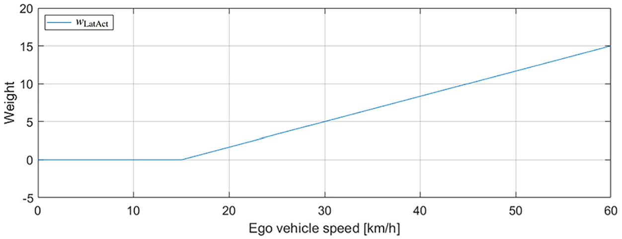
Visualization of lateral action cost weight.
Figure 7 shows the overall shape of the test track used in the simulations. The maximum speed of the test track is limited to 60 km/h, and the super-elevation is 0 throughout the entire section. Also, it consists of a total of three lanes, and the width of each lane is 3.5 m. To verify the effect of the proposed speed control method according to the curvature and considering acceleration and jerk, the results are compared with the MPC-based planner to which they are not applied.

A closed-loop test track. The black line indicates the reference path. The magenta and the blue lines represent left and right boundary, respectively. (a) A closed-loop test track. (b) Simulation snapshot. (c) Curvature of the road according to the distance.
Path tracking performance
To check the speed control effect of the proposed method, the path tracking performance was compared with other MPC-based planner that does not plan the speed. In this test, we used a planner proposed by Gutjahr et al.
25
as a representative planner for comparison because it also uses a linearized kinematic vehicle model. Since the MPC
25
uses a predefined speed profile, we used the speed profile generated by CarMaker IPG Driver model as shown in Figure 8 for it. On the other hand, our proposed planner does not require such speed profiles, we set the maximum speed

Speed profile generated by IPG Driver along the reference path.
Figure 9 shows the overall lateral error when driving the entire test track for each MPC-based planner. As shown in the figure, the proposed method has a smaller lateral error in most sections. This means that the proposed method has better path tracking performance than the case of using MPC. 25 The statistics on the lateral error measured while driving the entire track are shown in Table 3. As can be seen in the table, the lateral error of the proposed method was reduced by 46.4% on average compared with the MPC. 25

Comparison of path tracking performance for each MPC-based planner.
Path tracking error comparison.

The path tracking performance of the MPC 25 was highly dependent on a given speed profile. First of all, when the MPC 25 used the constant speed profile at 60 km/h in all sections, speed control was not performed even in the high-curvature track segment. As a result, side slip occurred significantly in the high-curvature track segment, and it failed to track the path. Therefore, the path tracking performance could not be compared in this case. Next, in the case of using the MPC 25 with the speed profile generated by IPG Driver, path tracking was performed while adjusting the speed. However, since the IPG Driver generated the speed profile without considering the non-slip condition, the vehicle did not satisfy the non-slip condition in most track segments in this case as shown in Figure 10. Thus, the difference between the kinematic predicted motion and the actual vehicle movement became large. On the other hand, since the proposed method uses a target speed that satisfies the non-slip condition according to the reference path curvature, the ego vehicle was sufficiently slowed down in the corner section. Therefore, the motion prediction error between the kinematic model and the actual vehicle model was reduced, even in the high-curvature path, and as a result, the average lateral error became smaller than that of the MPC. 25 Figure 11 shows the tire side slip angle while the vehicle traveled using each MPC. As shown in the figure, the proposed MPC has a smaller overall side slip angle. This implies that the difference between the movement predicted by the kinematic model and the actual motion is smaller.

Comparison of speed profiles.

Comparison of sideslip angle.
Note that the proposed MPC does not have a smaller lateral error in the entire track. In particular, in the track segment of [250 m, 335 m] (corresponding to region 1 in Figure 7(a)), the proposed MPC temporarily had a larger lateral error in the negative direction, even though the side slip angle was smaller than the case of using the MPC.
25
This is because of the effect of the weights used in this experiment. Referring to Figure 10, the driving speed in this region was over 30 km/h. In this case, since the weights
Driving comfort quality
We compared the driving comfort quality between MPC 25 and the proposed planner by comparing the acceleration and jerk. Additionally, we analyzed the effect of acceleration and jerk penalizing cost term (10) on driving comfort. Figures 12 and 13 show the acceleration and jerk applied to the vehicle while it follows the reference path using each algorithm, and Table 4 shows the statistics of these acceleration and jerk values. Note that the acceleration and jerk in Table 4 represent the magnitude of the vector where the longitudinal and lateral components are summed. As a result, acceleration was reduced by 30.2% compared to MPC 25 when cost term (10) was not used, and was reduced by 41.5% when (10) was used. Additionally, the jerk was reduced by 18.7% compared to MPC 25 before using the cost term (10), whereas it was reduced by 71.0% after using the cost term (10). The experimental results imply that the proposed planner had better driving comfort.

Acceleration profile.

Jerk profile.
Comparison of acceleration and jerk.

Since the MPC 25 does not use longitudinal acceleration and jerk constraints, it is possible to create a motion that changes the speed as quickly as possible. On the other hand, the proposed planner without (10) prevents unlimited longitudinal acceleration and jerk increase through its range constraints. Therefore, the average acceleration and jerk were reduced. However, proposed planner without (10) calculates the cost using only the path tracking error and speed error. As a result, the longitudinal acceleration and jerk sometimes reached the limit value to quickly reduce the speed error. Also, it generated a steering input that corrected immediately even if a slight path tracking error occurred, which led to an increase in the lateral jerk. On the other hand, the proposed planner additionally uses terms, including the curvature of the vehicle trajectory, longitudinal acceleration, and control inputs, that affect the overall acceleration and jerk increase for cost calculation. This led to a motion plan that also considers reducing the acceleration and jerk to minimize the overall cost. Thus, the proposed planner showed a smaller acceleration and jerk than the planner without (10) overall as shown in Figures 12 and 13. Through these two effects, the proposed planner increased the driving comfort quality.
Collision avoidance
Next, the collision avoidance ability of the proposed algorithm was verified. To check whether the proposed planner is able to plan a collision-free motion through vehicle following and overtaking, we prepared a scenario with the following four phases as shown in Figure 14. The prepared scenario starts with a situation in which a reference path is created along the center lane, only the center lane is empty, and the left and right lanes are blocked by preceding vehicles. First, a vehicle in the front-left performs a lane change to the center lane. Second, all lanes remain blocked by preceding vehicles. Third, the right-front vehicle moves away from the ego vehicle, but another vehicle approaching at high speed is detected from the rear-right. Finally, the approached vehicle moves away from the ego vehicle and the right lane becomes free. The default driving speed of ego vehicle is set as

Overall scenario for collision avoidance ability test.
Figure 15 shows the planned trajectories that correspond to the obtained motion sequences and the vehicle movements in bird’s eye view, and Figure 16 is the overall time gap and relative speed between the ego vehicle and the leading vehicle in the same scenario. In this figure, the section with “current time gap << 0” indicates that target speed candidate

Simulation snapshots of vehicle following and overtaking motions. The red and black boxes represent the ego vehicle and traffic vehicles detected within the sensing range, respectively. The predicted trajectories of the traffic vehicles are plotted with cyan lines, and the trajectory corresponding to the planned optimal motion sequence is indicated by the red lines. (a) Vehicle following motions in phases 1 and 2. (b) Vehicle following motions after canceling overtaking in phase 3. (c) Overtaking motions in phase 4.
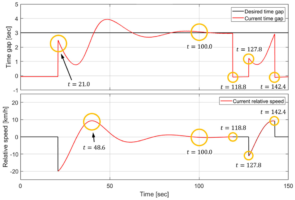
Time gap and relative speed in simulation shown in Figure 15.
In the overtaking scenario, to check whether the reduced lateral error cost weight
Figure 17 shows the acceleration and jerk profile when using

Comparison of driving comfort quality during high-speed overtaking for each lateral error cost weight. (a) Lateral acceleration. (b) Lateral jerk.

Comparison of side slip angle during high-speed overtaking. (a) Front tire side slip angle. (b) Rear tire side slip angle.
Conclusions
We propose an MPC-based motion planner that can improve path tracking performance and perform collision avoidance while considering acceleration and jerk minimization. The proposed MPC is capable of avoiding collisions with obstacles through vehicle following and overtaking. For comfortable motion generation, the cost function is designed including longitudinal acceleration and jerk penalization. In addition, cost weights for vehicle curvature and curvature change were made as a function of speed, such that the importance of minimizing lateral acceleration and jerk increases as the speed increases. In a situation where overtaking is required, the lateral error cost weight for each time step is divided by the prediction horizon length. This process prevents the lateral error cost from significantly increasing as a result of the continued lateral deviation, and enables smooth overtaking. We also determine the target speed by comprehensively considering path tracking on curved roads and whether it is possible to overtake obstacles to ensure vehicle safety. For this, we calculate two target speed candidates. The first candidate is determined using the road curvature and non-slip condition. This candidate is to prevent lane departure due to unexpected motion by reducing the difference between the kinematic vehicle model and actual movement. The second candidate is determined by using the time gap and relative speed between the ego vehicle and the leading vehicle, such that the ego vehicle travels at the same speed as the leading vehicle with a sufficient distance when overtaking is impossible. The effectiveness of the proposed planner was evaluated through road driving scenarios with various curvatures and collision avoidance scenarios in simulations. In the track driving scenario, including various curved roads, not only the path tracking performance but also the driving comfort were improved. Compared with the case where all cost weights were set to the same constant and road curvature was not considered, the average path tracking error was reduced by 46.4%, and the average acceleration and jerk were decreased by 41.5% and 71.0%, respectively. Furthermore, in the collision avoidance scenario, the ego vehicle succeeded in driving without collision through vehicle following and overtaking. In particular, in the overtaking scenario, when the reduced lateral error cost weight was used, both lateral acceleration and jerk were reduced by more than 50% compared with the case where the lateral error cost weight was not reduced, and driving comfort was greatly improved. The simulation tests confirmed that the proposed planner can generate motions that ensure vehicle safety and improve driving comfort. Future work will be devoted to evaluating the driving comfort, path tracking, and collision avoidance ability of the proposed planner in various scenarios.
Footnotes
Handling Editor: Chenhui Liang
Declaration of conflicting interests
The author(s) declared no potential conflicts of interest with respect to the research, authorship, and/or publication of this article.
Funding
The author(s) disclosed receipt of the following financial support for the research, authorship, and/or publication of this article: This work was supported by the National Research Foundation of Korea (NRF) grant funded by the Korea government (MSIT) (No. 2019R1F1A1059496) and the DGIST R&D Program of the Ministry of Science and ICT (22-CoE-IT-01).