
Abstract
Thermal radiation and vacuum lead to the deformation of bearing cylinder with carbon fiber composites which generates the defocus phenomenon for space optical camera. As heavier weight and higher complexity of the rigid focusing mechanism for the space optical camera, a novel compliant focusing mechanism with lighter weight and simple structure was designed and tested in this paper. In order to achieve stroke range and ensure image quality for the compliant focusing mechanism, micro driving displacement from the piezoelectric ceramics was amplified by two-stage flexible hinge lever-type mechanism. Taking the size parameters of the flexure hinges and beams as the design variables, an optimization model of the compliant focusing mechanism was established in which minimizing weight was considered as objection function under the stroke requirements. Consequently, optimal structure parameters of the compliant focusing mechanisms under different input forces can be obtained under the allowable stress and lighter weight. The effectiveness of the proposed compliant focusing mechanism was verified by the simulations and experiments. The results show that the compliant focusing mechanism can achieve a stroke of 2 mm for the focal plane assembly. The proposed method provided a new idea to design the focusing mechanism with lighter weight, simpler structure and higher reliability.
Introduction
Space optical camera plays a very important role in the fields of resource survey, disaster warning and meteorological observation. The target image should be accurately imaged on the sensor of the space optical camera, which ensures the high-resolution image. Thermal radiation and vacuum in space environment affect the deformation of the bearing cylinder with carbon fiber composites, which results in defocusing phenomenon of the optical camera. Therefore, focusing mechanism is a important component to obtain clear image for the space optical camera.
Traditional focusing mechanism composed of the rigid mechanisms are usually used to adjust the focal plane. Such as, the 6-DOF parallel mechanism was used in the Gaia space telescope with a positioning accuracy of 5 μm and a resolution of 0.2 μm.1,2 Stepper motors and non-back drivable linear actuators were employed in the focus and alignment mechanism which can position the fused silica, spherical pick-off mirror in the optimal tip, tilt and piston position for the near infrared camera of the James Webb space telescope. 3 The traditional focusing mechanisms are usually consist of the high-precision worm gear, ball screw and stepper motor. Although it can achieve high-precision focusing, increasing complexity, higher weight and launch cost seriously limit the its application.
In order to decrease the complexity and weight of the rigid focusing mechanism, a compliant mechanism actuated by piezoelectric ceramic (PZT) was viewed as the novel method to design the focusing mechanism. 4 The compliant mechanism provides high-precision motion and transmit force, motion and energy by virtue of its material deformation. It has the advantages of no gap, no friction and no maintenance and widely used in the micro-electro-mechanical system (MEMS), aerospace and medical equipment.5–8 Tang et al. designed a novel flexure-based 3-degree-freedom elliptical micro-positioning motion stage to obtain translation motions along the x, y, and z directions with high working bandwidth. 9 A micro gripper based three-stage amplified compliant mechanism actuated by the PZT was achieved to grip the micro parts by Chen et al. 10 It can be seen that the compliant mechanism is the better choice to design the high-precision focusing mechanism.11,12 In virtue of the larger output force, higher stiffness and fast response speed, the PZT actuator is usually used for ultra-precision motion and positioning. 13 However, the output displacement of the PZT actuator is more small and cannot achieve the design requirements of large strokes. Therefore, the PZT actuator and displacement amplifier are cooperated to achieve the larger range and force for the focusing mechanism.
The multistage lever-type mechanism is the most common displacement amplifier which has been widely used in parallel robots, precision positioning platforms and other fields.14,15 Compared with the bridge-type amplifying mechanism, it has the advantages of simpler structure, higher bearing capacity and larger magnification. Accurate model of flexure hinges is the key to design and optimize the multistage lever-type amplifier. Some scholars proposed the compliance matrix of elliptical and circular hinges, which effectively described the deformation of compliant mechanisms composed of the circular, parabolic and elliptical flexible hinges.16–18 Subsequently, many novel models and methods have been developed to design the lever-type amplifying mechanisms.19,20 Ma et al. designed a new piezoelectric linear actuator with a symmetrical lever-type displacement amplifying mechanism based on a uniaxial double-slot right circular flexible hinge. 21 It can achieve a large displacement for the driving part and sufficient clamping force for the clamping part. Jung and Kim designed a piezoelectric actuated platform which was composed of a multi-levers amplifying mechanism and had a magnification of more than 60 times. 22 Choi et al. proposed a motion platform driven by the PZT using symmetrical planar multiple lever-type mechanism which has a magnification of more than 20 times. 23 A piezoelectric pump with the lever-type hinge mechanism was designed by Ham et al. 24 The small displacements could be amplified by a factor of 10 using the pump. Consequently, the lever-type mechanism is more suitable to design motion platform with simpler structure and larger magnification.
Although the lever-type mechanism has the potential to achieve higher magnification (60 times by Jung and Kim 22 ), the load-carrying capacity is more small. So, it is more suitable for the MEMS and minimally invasive medical devices. Moreover, the light weight of compliant focusing mechanism is the key to design the space optical camera. However, optimization design of integrating the structure parameters and lighter weight for the compliant focusing mechanism is rarely reported. A novel compliant focusing mechanism for the space optical camera was proposed to achieve the higher magnification ratio and lighter weight in this paper. The size parameters of the flexure hinges and beams were defined as the design variables. Optimal structure parameters of compliant focusing mechanism can be obtained by the optimization method. Simulation and experiments were implemented to verify the effectiveness of the novel compliant focusing mechanism with lighter weight and larger stroke.
Section 2 presented the simplified structure of the focusing mechanism based on the two-stage flexible hinge lever-type mechanism. Section 3 deduced the design model and optimization process of the compliant focusing mechanism. Deformed simulation and modal analysis of the proposed compliant focusing mechanism were implemented in Section 4. Experiment and evaluation of the optimal compliant focusing mechanism were described in Section 5. The conclusion was given in Section 6.
Structure description of the compliant focusing mechanism
The optical system of the space optical camera is mainly composed of four parts: the main mirror, the secondary mirror, the third mirror and the reflector. The primary and secondary mirrors are installed in the bearing cylinder with carbon fiber reinforced resin matrix composites. The simplified schematic diagram of the optical system of the space optical camera is shown in Figure 1.

Simplified optical system schematic of a space optical camera.
The overall size of the space optical camera is 1700 mm × 650 mm × 750 mm. The focal distance, focus depth and pixel size is respectively 5 m, ±0.2 mm, and 10 µm. The size of the focal plane is 200 mm × 100 mm × 45 mm (length, width, and height). Due to the vibration in launch process and thermal radiation in space, the bearing cylinder with carbon fiber composites is deformed, which changes the optical path and causes the defocus. Therefore, a focusing mechanism is required to adjust the focal plane to obtain a clear image. In virtue of the obvious advantages, compliant mechanism and the PZT were combined to design the focusing mechanism for space optical camera in this paper. According to the design requirements of the space optical camera, simplified structure diagram of the compliant focusing mechanism based on the two-stage flexure hinge lever-type mechanism and the PZT is shown in Figure 2.

Simplified structural schematic of the compliant focusing mechanism based on a two-stage flexural hinge lever-type mechanism.
The compliant focusing mechanism is composed of two symmetrical two-stage flexure hinge lever-type amplifiers and the PZT actuators. The two-stage flexure hinge lever-type mechanism is manufactured of aluminum alloy (7075-T651) with 455 MPa for the yield strength, 71 GPa for the elastic modulus and 0.33for the Poisson’s ratio. The actual focal plane assembly weighs 2 kg which is composed of charge coupled devices (CCD), support frame with invar alloy, printed circuit board and heating tube. In Figure 2, a thin rectangular plate is used to replace the actual focal plane assembly. It should be noted that since the optical camera is a weightless state in space, the load of the focal plane assembly on the compliant mechanism is negligible. The symmetrical two-stage flexure hinge lever-type amplifier is adopted to eliminate the parasitic displacement. The focusing mechanism is driven by a square laminated piezoelectric ceramic (model: 150/5×5/20 H) with maximal output force of 1600 N and maximal displacement of 24 μm. According to deformation of the bearing cylinder and the light paths, the focal plane should be moved within 2 mm along the vertical direction to ensure a clear image. Therefore, input displacement from the PZT needs to be magnified by 100 times to achieve the clear image using the two-stage flexible hinge lever-type mechanism.
Modeling and optimizing of the compliant focusing mechanism
Amplification ratio
The amplification ratio of the two-stage flexible hinge lever-type mechanism is the key to design the compliant focusing mechanism. Four groups of identical two-stage flexible hinge lever-type mechanisms are adopted to support the focal plane and realize movement along the vertical direction in the paper. In order to simplify the calculation model, only one of the two-stage flexure hinge lever-type mechanism is investigated and its simplified structural schematic is shown in Figure 3.

Simplified structural schematic of the two-stage flexural hinge lever-type mechanism.
The upper beam and lower beam are in contact at point 2. The symmetrical structure offsets the parasitic displacement in x direction at the output point and only the displacement in y direction is considered in the paper. l1, l2, l3, l4 represent the length of the upper and lower beams for the lever-type mechanism in x direction. r1, r2 and t1, t2 respectively denote the radius and longitudinal section thickness of flexure hinges for the upper and lower beam. h1, h2 and b1, b2 respectively represent the height and thickness of the upper and lower beams. Fin denotes the input force from the PZT. uin and uout denote the input and output displacements. G represents the external load from the focal plane.
The deformation of the upper beam can be deduced from the deformation of the flexible hinge and rectangular beam with constant cross section. The deformation of the symmetrical semicircular flexible hinge at point 1 can be obtained by Lobiotiu’s theory 25 and expressed as:

where, E represents the modulus of elasticity, the superscript h represents the flexure hinge, Fr represents the interaction force between the upper beam and lower beam, r1 represents the radius of the flexure hinge of the upper beam,

The deformation of the upper beam with constant rectangular section can be obtained by the Euler beam theory and expressed as:
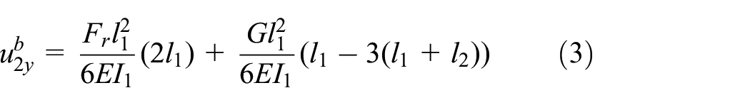
where, I1 represents the inertia moment around z axis of the upper beam with constant rectangular section; the superscript b represents the beam,


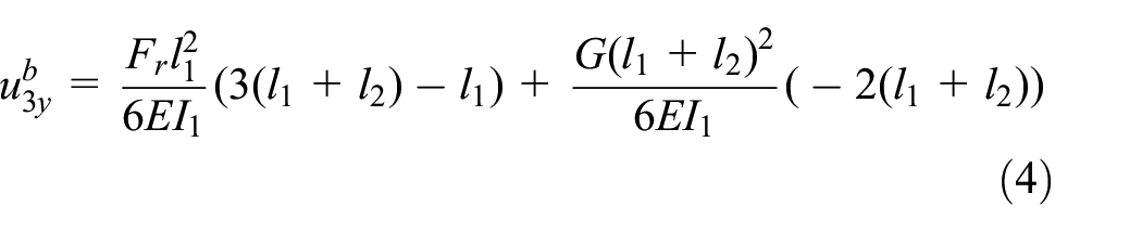
The calculation process of the lower beam is similar to the upper beam. Therefore, using the same theory, the deformations of the lower beam can be obtained (symbols notation are same as the upper beam) and expressed as:


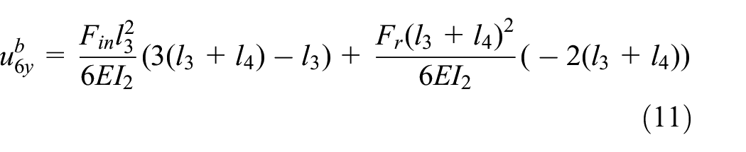
where, I2 represents the inertia moment around z axis of the lower beam with constant rectangular section,

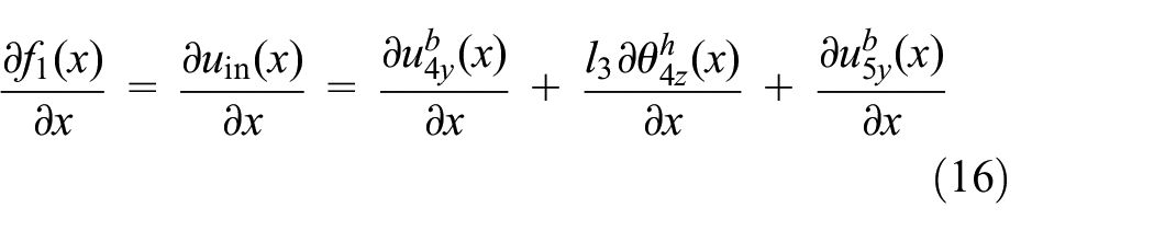
The interaction force Fr can be obtained by solving equation (12). Then, Fr is substituted into equations (1), (3), (4), (9), (10), and (11). Based on the above information, uin and uout can be respectively derived from equations (7) and (6). Therefore, the amplification ratio of the two-stage flexible hinge lever-type mechanism can be expressed as:

Optimization model
The amplification ratio of the two-stage flexure hinge lever-type mechanism is closely related to the flexibility matrixes of the flexure hinges. According to the Lobiotiu’s theory, the flexibility matrix of the symmetric circular flexure hinge can be determined by the size parameters (r1, r2, t1, t2) of the flexure hinge. Weight of flexible hinges is very light and negligible. Therefore, the total weight of the two-stage flexure hinge lever-type mechanism is determined by the size parameters (h1, h2, b1, b2, l1, l2) of beams. An optimization model of the two-stage flexure hinge lever-type mechanism with light weight is established and expressed as follows:

where,
Sensitivity analysis and solution
Sensitivity analysis is the key to solve the optimization problems based on gradient optimization algorithm. According to equation (14), the sensitivities of the objective and constraint functions to the change of the design variable x are respectively deduced and expressed as:


The sensitivities
A globally convergent method of moving asymptotes (GCMMA) belonging to a convex programing method was adopted to solve the optimization model of the compliant focusing mechanism in the paper. 26 The flow chart of the optimization process was shown in Figure 4 and specific steps were as follows:
Step 1: Optimization parameters were firstly initialized. They include design variables
Step 2: The objective function f0(
Step 3: The sensitivities of objective and constraint functions to the change of design variable x were respectively deduced based on the current design variables
Step 4: The design variables vector
Step 5: If ∣

The solution flowchart of the optimization process.
Optimization results and simulation analysis
In order to investigate the effectiveness of the proposed method, the optimization process and results under different input forces Fin = 100 N, Fin = 150 N, Fin = 200 N, Fin 300N, and Fin 400 N were implemented. The initial design variables were defined as r1 = r2 = t1 = t2 = h1 = h2 = 4mm. Based on the previous research, the allowable range of size parameter for the flexure hinges and beams were respectively set as [1 mm,15 mm] and [1 mm, 40 mm]. The allowable error of optimization convergence was defined as ε = 0.001. The other structural sizes of the two-stage flexible hinge lever-type mechanism were constant in the optimization process and listed in Table 1.
Structural sizes of the two-stage flexural hinge lever-type mechanism.

Based on the optimization model, Figure 5 shown the iterative curves of the objective function f0 and constraint functions f1, f2, f3 under the different input forces. The optimization process was gradually stable and convergent. It verifies the effectiveness of the proposed method to design focusing mechanism. It can be seen from Figure 5(a) that the stable values of the objective functions are 79g, 58g, 52g, 47g, 46g under the input force Fin = 100N, Fin = 150N, Fin = 200N, Fin = 300N, Fin = 400N. As the input force is increased, the value of the objective function gradually is decreased and the total weight of the focusing mechanism is more and more lighter. From the Figure 5(b) and (c), the input and output displacements of the two-stage flexure hinge lever-type mechanism can satisfy the constraint requirements. Table 2 listed the optimal size parameters of the two-stage flexure hinge lever-type mechanism under different input forces.

Iterative curves of the optimization process under different input forces: (a) objective function f0, (b) constraint function f1, (c) constraint function f2, and (d) constraint function f3.
Optimal size parameters of compliant focusing mechanism with different input forces.

3D models of the two-stage flexure hinge lever-type mechanism under the different input forces were constructed. Subsequently, deformed simulations and model analysis were performed to verify the feasibility of the proposed compliant focusing mechanism using the finite element method (FEM). The output displacements and Von-Mises stress under the different input forces were shown in Figure 6. The output displacement under different input forces can approximately reach at 2 mm. The results are consistent with the optimization results and verify the effectiveness of the proposed compliant focusing mechanism for the space optical camera.

Output displacements and Von-Mises stresses of the two-stage flexure hinge lever-type mechanism under the different input forces: (a) Fin = 100 N, (b) Fin = 150 N, (c) Fin = 200 N, (d) Fin = 300 N, and (e) Fin = 400 N.
The curves of maximal stress and the total weight of compliant focusing mechanism under the different input force Fin were shown in Figure 7. As the input force is increased, the maximal Von-Mises stress of the focusing mechanism is gradually increased. When the input force is increased to 200 N, the Von-Mises stress was 239.2 MPa which has exceeded the allowable stress of the material (safety factor is 2). Moreover, the total weight (objective function f0) was gradually decreased with the increase of input force. However, when the input force is increased to 300 N, the objective function is converged to about 47g. At the moment, the reduction of total weight was not obvious. Consequently, the balance between total weight and maximal stress was very important of the compliant focusing mechanism. If the input force is increased, the total weight will become lighter and the maximal stress will become larger. From the Figure 7, the output displacement under the Fin = 150 N can reach at 2.0493 mm and maximal stress is 197.54 MPa which satisfies the allowable stress of the material. Consequently, size parameters under the input force Fin = 150 N were selected to design the two-stage flexible hinge lever-type mechanism with lighter weight and allowable stress.
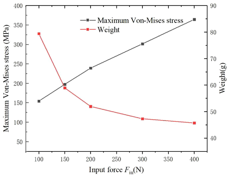
Curves of maximal stress and the total weight of the compliant focusing mechanism under different input force Fin.
In order to avoid the resonance in space, the modal analysis of the two-stage flexure hinge lever-type mechanism under the Fin = 150 N was investigated to obtain the natural frequency and mode using the FEM. Figure 8 shown the first four order vibration modes and natural frequencies of the two-stage flexure hinge lever-type mechanism. The first four order natural frequencies respectively were 129, 144, 175, and 973 Hz, which were larger than the spatial excitation frequency (generally less than 100 Hz). Moreover, the vibration frequency in the emission stage was 70 Hz which was lower than the first-order frequency of 129 Hz. Moreover, the two-stage flexure hinge lever-type mechanism was closed in the launching stage. When it is working in space, the focusing mechanism is opened and can achieve different motion by adjusting the voltage of the PZT. So, the proposed focusing mechanism of the space optical camera can successfully avoid the external vibration and further ensure image quality.
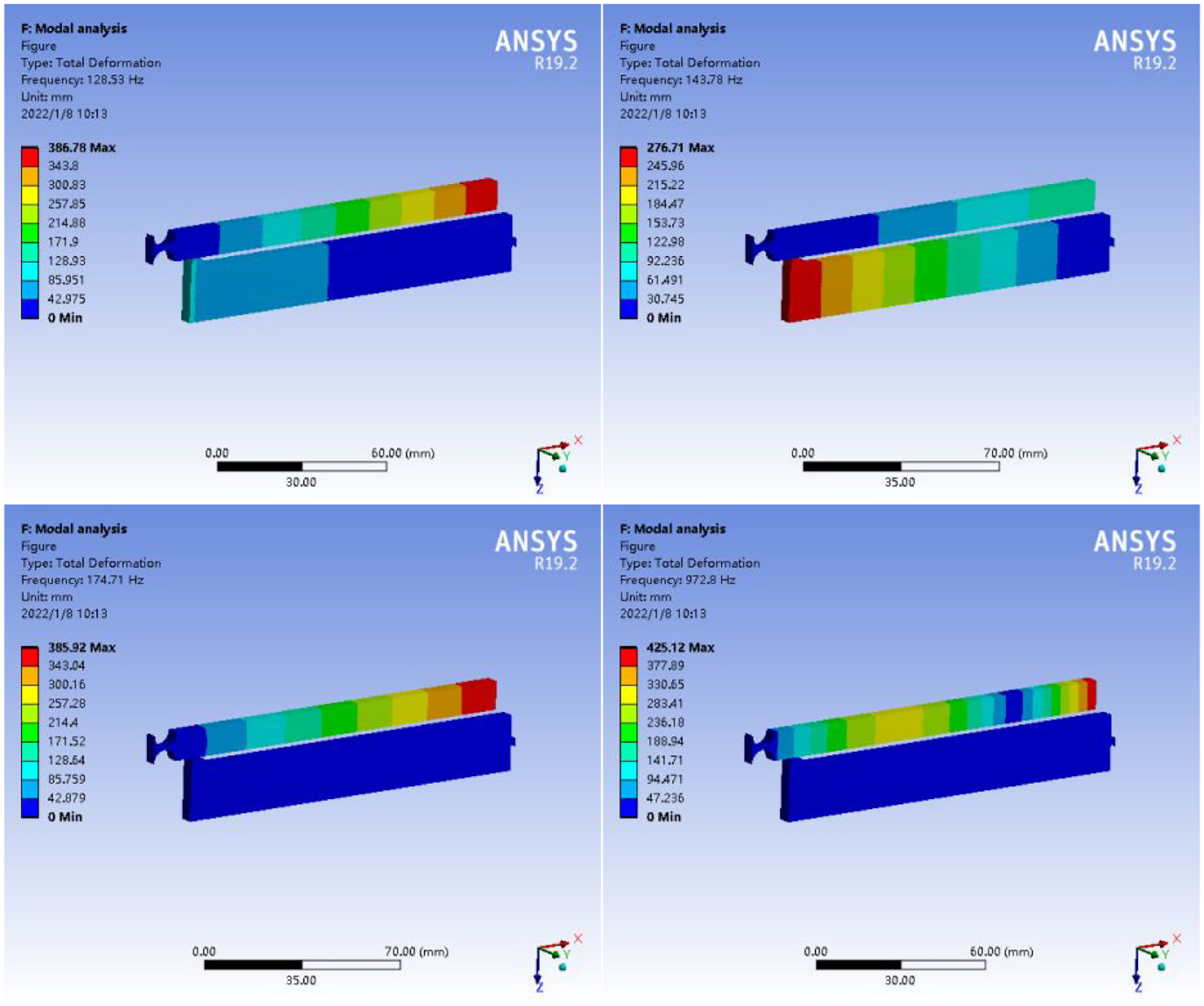
The first four order vibration modes and natural frequencies of the two-stage flexure hinge lever-type mechanism.
Experiment and analysis
The compliant focusing mechanism based on the two-stage flexible hinge lever-type mechanism under the input force Fin = 150 N was fabricated by laser cutting technology and the experimental platform was established as shown in Figure 9. Displacement experiments of the compliant focusing mechanism under the input force Fin = 150 N were investigated.
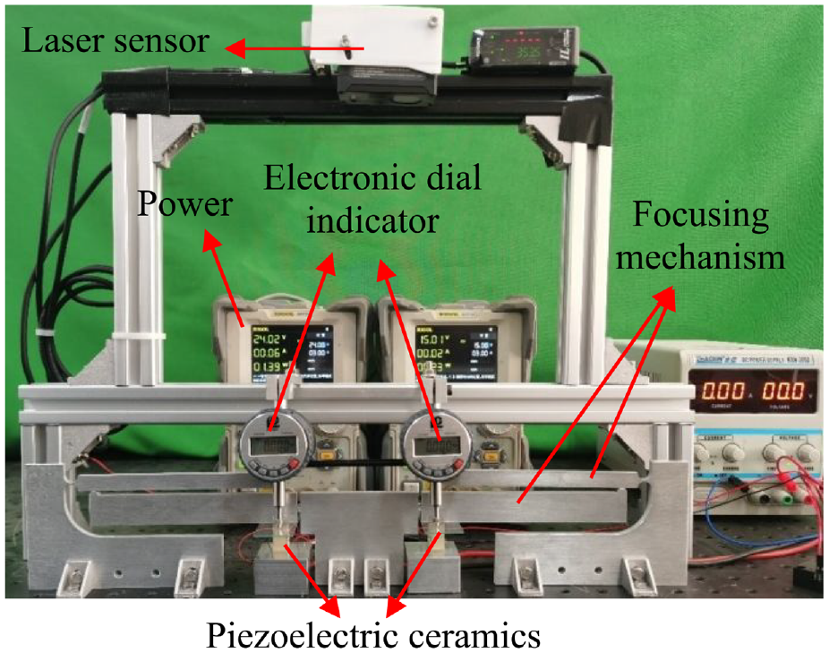
Experimental platform of compliant focusing mechanism based on the two-stage flexible hinge lever-type mechanism.
The displacement of the focal plane in the vertical direction was generated by the combination of two-stage flexible hinge lever-type mechanism and the PZT. Electronic dial gauge (range: 0–6.5 mm, repeatability: ±0.003 mm) and laser sensor (range: 200–1000 mm, repeatability: ±0.05 mm) were respectively used to measure the input and output displacements. Square laminated piezoelectric ceramics (PSt 150/5 × 5/20 H) were used to generate the input force. The power supply and analog input voltages were respectively set as 15 V and 0–10 V. Output displacement from the piezoelectric ceramic can be directly measured by the electronic dial gauges.
Based on the established experimental platform, deformation of the compliant focusing mechanism in initial and target states were shown in Figure 10. In initial stage, the analog input voltage and output displacement of the PZT were set as 0. Digital indications of the electronic dial gauges and laser displacement sensor were respectively 0 and 353.5 mm. When the input voltage of the PZT was set to 10 V, the deformation of the compliant focusing mechanism was shown in Figure 10(b). Digital indications of the electronic dial gauges and laser displacement sensor were respectively as 21 μm, 22 μm, and 355.6 mm. Consequently, the displacement at the input point of the compliant focusing mechanism were respectively 21 μm and 22 μm. The displacement at the output point was reached at 2.1 mm which was approximately consistent with the theoretical analysis. Therefore, experimental results verified the effectiveness of the proposed method to design the two-stage flexure hinged lever-type mechanism.

Initial and final experimental deformation of focusing mechanism based on two-stage flexible hinge lever mechanism: (a) initial stage and (b) final stage.
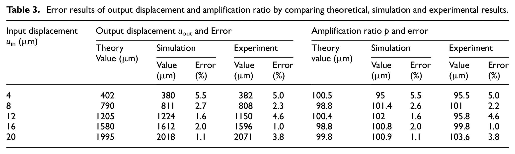
In addition, deformation experiments of compliant focusing mechanism with different input displacements derived from the PZT were implemented by the experimental platform. The input displacements were defined as the 4, 8, 12, and 16 mm. The output displacements uout and the amplification ratios p were investigated with the different input displacements. Comparing the theoretical, simulation and experimental results, the error results of the output displacement and amplification ratio were listed in Table 3. The error of the output displacement uout is equal to the error of the amplifier ratio. Its reason is the fact that the amplification ratio is proportional to the output displacement under the certain input displacement. The maximal errors of the uout and p are respectively 5.0% and 5.5% when the input displacement is 4 μm. The maximal error of the output displacement between theoretical and experimental results is 0.076 mm. Since focal length range of the space camera is ±0.2 mm, the maximal error 0.076 mm is less than the error range. So, the maximal error can’t affect the image clarity. The compliant focusing mechanism proposed in the paper can achieve design requirements of the space camera.
Error results of output displacement and amplification ratio by comparing theoretical, simulation and experimental results.
The experimental errors were mainly derived from manufacturing, assembly and measurement accuracy. The error from the laser cutting was key reason to influence the manufacturing accuracy. In addition, the contact type method to measure input displacement inevitably generated measurement errors. The installation accuracy of the measurement system also leaded to large measurement errors. Future research will improve the accuracy using a high-precision non-contact measurement system.
Conclusions
This paper proposed a novel compliant focusing mechanism for space optical camera which had the characteristics of lighter weight and larger stroke. The compliant focusing mechanism was composed of a flexible hinge lever-type amplifier and a PZT. The PZT were used to provide the driving force and output displacement was amplified by a two-stage flexible hinge mechanism. Considering the lighter weight, two-stage semicircular flexure hinge lever-type mechanism was achieved by the optimization theory. The effectiveness of the proposed method was verified by simulation and experiment. The results were discussed and as following:
The size parameters of the semicircular flexure hinge and the upper and lower beams were defined as design variables. The minimal total weight of the focusing mechanism was taken as the optimization function. The GCMMA optimization strategy was used to optimize the two-stage flexure hinge lever-type mechanism to achieve the lightweight and large stroke.
With increase of the input force from the PZT, the maximal stress was increased and the total weight of the two-stage flexure hinge lever-type mechanism was gradually decreased.
Comparing theoretical calculation, simulation and experimental results, the correctness and effectiveness of the proposed compliant focusing mechanism were proved. In addition, the focusing mechanism designed by the optimization method can realize the movement of the focal plane assembly within a range of 2 mm and the total weight was significantly reduced.
Footnotes
Acknowledgements
The authors would like to thank the National Natural Science Foundation of China under Grant No. 51375383 and the Natural Science Basic Research Program Foundation of Shaanxi Province of China under Grant No. 2022JM-197.
Handling Editor: Chenhui Liang
Author contributions (Roles)
Yan Li performed significantly the data analyses and wrote the manuscript; Bo Liu performed the experiment; Wenjie Ge contributed to the conception of the study; Xinxing Tong provided the constructive discussions.
Declaration of conflicting interests
The author(s) declared no potential conflicts of interest with respect to the research, authorship, and/or publication of this article.
Funding
The author(s) disclosed receipt of the following financial support for the research, authorship, and/or publication of this article: This work was supported by the National Natural Science Foundation of China under Grant No. 51375383 and the Natural Science Basic Research Program Foundation of Shaanxi Province of China under Grant No. 2022JM-197.
Ethical approval/Patient consent
There is no ethical approval /patient consent.