
Abstract
Among all kinds of journal bearings, the tilting pad bearing has the characteristics of high stability. In order to further reduce the vibration and improve the stability of rotor-bearing systems, a novel double layers flexible support tilting pad bearing (DL-FSTPB) is presented in this paper. The bearing utilizes two layers of springs, which have different functions. The offset springs control the swing angle of the tilting pad to ensure the formation of a convergent oil film, and the symmetrical springs are used to change the bearing stiffness coefficient, increase the bearing elasticity, and improve the ability to accommodate misalignment. Experiments were carried out to study the vibration characteristics of the rotor system. The results were analyzed using wavelet analysis of acceleration and displacement, waterfall plots, a wavelet analysis, a run-up process and shaft center orbits areas. The results show that the DL-FSTPB exhibits excellent vibration attenuation characteristics, which can effectively reduce the amplitude and the system vibration level.
Introduction
Tilting pad (TP) journal bearings have been studied by many scholars due to its inherent stability characteristics,1,2 but it also has defects such as stress concentration at the fulcrum and low damping. 3 As shown in Figure 1(a), the flexible pivot pad journal bearing (FPJB) is an innovative design of the tilting pad bearing, which is machined by wire electrical discharge machining (EDM). The innovative design of changing the fixed fulcrum of the bearing pads to flexure pivots support not only simplifies the bearing structure, but also inherits the excellent performance of TP.4,5
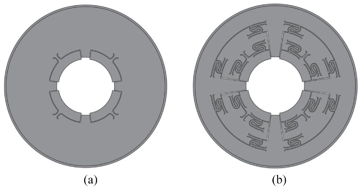
Bearing structure diagram: (a) FPJB and (b) DL-FSTPB.
With the development of modern rotating machinery in the direction of high speed and large-scale, there are more and more factors that cause system instability, such as sealing force, internal friction, and unbalanced mass excitation. 6 It is of great practical engineering significance to improve the dynamic stability of the rotor-bearing system by changing the bearing structure to improve the support damping characteristics.
The damper bridge uses two integral electric discharge machined EDM “S” springs originally developed for use in combination with squeeze-film dampers as a parallel support centering spring. It was then commonly used as a bearing support damper for flexure pivot bearings. 7 The improved integral squeeze film damper (ISFD) is simple and compact due to its integration into the entire via wire-cut manufacturing. Ertas et al. 8 experimentally studied and predicted the stiffness and damping coefficients of ISFD under varying end seal clearances, excitation frequencies, and vibration amplitudes. Agnew and Childs 9 performed parameter identification testing on a ISFD and flexure pivot bearing with and without “locking” the damper. Their results further validated the effectiveness of the soft support and damping capability by showing an increased damping to stiffness ratio with the damper engaged. San Andre’s and De Santiago 10 presented the measurements of the unbalanced response of a massive 45 kg rotor supported on series (flexure pivot) tilting pad bearings and ISFDs, demonstrating the effectiveness of the flexible damped support in reducing the system critical speed and improving the overall rotor response with reduced transmitted forces to ground. The above studies demonstrate the effectiveness of flexure pivots in series with the “S” integral springs dampers.
Ertas11,12 introduced the hybrid gas bearing (HGB) which is offset integral springs supported, and describes the design and principle of operation in detail. Ertas et al. 13 presents test results of a 70 mm HGB in a component level rig, and the results showed that the HGBs have favorable ability to accommodate large unbalance loads, well-damped in the critical speeds, and inherent bearing stability at ultrahigh speeds. The above experiments demonstrate the utility of offset integral spring dampers. Ertas and Delgado 14 advanced a novel hermetically sealed squeeze film damper (HSFD) concept and demonstrate better damping levels than squeeze film damper (SFD). Delgado and Ertas 15 presented a new compliantly damped hybrid gas bearings (CHGB) design that introduces a novel HSFD as an alternative to metal mesh dampers (MMD) to further improve bearing damping. Direct comparisons to experimental results for a CHGB using MMD shows 3X increase in direct damping levels when using HSFD in the compliant bearing support. Ertas and Delgado 16 presented a novel gas bearing concept that combines an HSFDs in parallel with “S” integral spring dampers as a bearing support. The research demonstrated that the gas bearing-support damping levels using HSFD that rival conventional open-flow SFD in industry. Delgado and Ertas 17 analyzed the rotor-dynamic of CHGBs supported by HSFD in parallel with “S” integral spring dampers for various operating conditions, and studied the effect of HSFD on rotor vibration control theoretically and experimentally, and the results showed that HSFD can significantly increase the damping level and can effectively reduce the vibration level of the rotor system. Feng et al. 5 proposed a comprehensive theoretical model of the bearings which coupling the flexure pivot tilting pad gas bearing (FPTPGB) model and MMD model, and the results showed that the direct damping coefficients of the bearings in this study are higher than those of FPTPGBs. The above studies demonstrate the effectiveness of the dampers in parallel with each other.
Symmetrical “S” integral springs are mostly used in the design of oil film dampers, and the offset “S” integral springs are currently mainly used in gas tilting pad bearings, and researchers have not yet applied it to oil-lubricated bearings. The asymmetrically positioned integral springs support two functions by allowing radial motion and pad rotation, which increase bearing elasticity and enhance hydrodynamic wedge and maximize load capacity. The offset “S” integral springs will produce both elastic deformation due to the tilting of the pad’s swing angle and load direction deformation due to loading, which increases the difficulty in the design of the “S” integral springs. Based on the above research background, this paper presents a novel double layers flexible support tilting pad bearing (DL-FSTPB) concept, that is, on the back of the oil-lubricated tilting pad, the offset “S” integral springs is connected in parallel with the flexure pivot to realize the design of convergent lubricating oil film, and then the structure is connected in series with the symmetrical “S” integral springs to realize the deformation of the bearing direction and improve the elasticity of the bearing. This concept was developed to separate the two functions described above in order to achieve the optimal effect of designing bearings, and providing good vibration damping of bearings.
Double layers flexible support tilting pad bearing structure
Figure 1(a) is a FPJB, which is supported by flexure pivots, and the flexure pivots have certain structural rigidity. When the rotor is running, the bearing pad is deflected, and the bearing pad can adaptively adjust the deflection angle according to the oil film force. Figure 1(b) shows a novel DL-FSTPB, in which each pad is supported by offset “S” integral springs in parallel with a flexure pivot and then in series with symmetrical “S” integral springs. The pair of symmetrical “S” integral springs machined to the bearing house provide stiffness to the bearing system. The other pair of “S” integral springs machined with the flexure pivot are asymmetrical springs, the springs are offset to enhance the hydrodynamic wedge.
The DL-FSTPB is processed by wire EDM, which can achieve high-precision structures of “S” integral springs and flexure pivots. The surface of the bearing pads is sprayed with babbitt alloy with a thickness of 1 mm, so that the bearing can form a good lubricating friction pair with the rotor and can avoid the wear of the shaft. The basic parameters of the bearing system are shown in Table 1.
Basic experimental parameters of bearing system.

Xiong 18 studied the stiffness of the flexure pivots of FPJB, and the results show that the radial stiffness of the flexure pivots is relatively large, and the impact on the stiffness of the bearing can be ignored. The flexure pivots supporting the bearing pads ensure the stable operation of the bearing by deflecting the bearing pads due to the deformation caused by their own structural characteristics, and the deflection of the bearing pads is related to the rotation stiffness. Therefore, the radial stiffness of the flexure pivots of DL-FSTPB is relatively large, and the offset springs are connected in parallel with the flexure pivots, so the parallel stiffness of the offset springs and the flexure pivots is relatively large, and the influence on the stiffness of the bearing can be ignored. The stiffness of the bearing is mainly determined by the stiffness of the symmetrical spring and the stiffness of the oil film.
The load deformation analysis of the double layer springs is simulated by ANSYS software. Since the theoretical calculation method of DL-FSTPB has not been established, in this paper, the oil film pressure of FPJB is used to calculate the pad deformation of DL-FSTPB.
In the FPJB, the relative movement between rotating journal and inner surface of pads produces pressure on the oil film between the wedge-shaped clearance. The pressure of the oil film is described by Reynolds equation, which simplified form is as follows:
In the above equation: x, z represents the bearing coordinates, h represents oil film thickness, p represents oil film pressure, μ represents the dynamic viscosity of the lubricating oil, ω represents journal speed, r represents the journal radius.
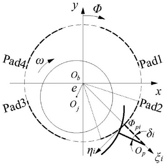
The calculation model of tilting pads bearing-rotor system is shown in Figure 2, the origin of coordinate system xOby coincides with the bearing center Ob, Oj is the journal center, Op is the center of the pad support, e is the eccentricity between journal center and bearing center,

Geometric model of the FPJB.
ω is the rotating shaft speed, δi is the swing angle of the i-th pad, Φ is the rotation angle from the Y-axis, Φpi is the pivot position angle of the i-th pad, ξi is the radial displacement of the i-th pad, ηi is the tangential displacement of the i-th pad. It can be seen from the calculation model that the equation of the oil film thickness of FPJB is 18 :
In this equation: c is the radius clearance, m is the preload factor, m = (c- c′)/c, and c′ is the assembling clearance.
The finite difference method is used to solve Reynolds equations and the pressure distributions of each pad of FPJB is numerical solved.
The rotor rotates clockwise and is supported symmetrically by the bearings, and the bearing load mode is the load between pad. The parameters of two computational working conditions of bearings are shown in Table 2, and the geometric parameters are shown in Table 1. The oil film pressure of the pad at the bottom-right of the bearing in Figure 1(a) is calculated as shown in Figure 3. The oil film pressure of FPJB is added to the pad of DL-FSTPB to calculate the spring deformation, and the results are shown in Figures 4 to 7.
Parameters of two computational working conditions of FPJB.


Oil film pressure of the pad at the bottom-right of FPJB under different average pressures: (a) 1 MPa and (b) 1.5 MPa.

Strain of the bearing pad under the oil film pressure at different average pressures: (a) 1 MPa and (b) 1.5 MPa.

Stress of the bearing pad under the oil film pressure at different average pressures: (a) 1 MPa and (b) 1.5 MPa.

Strain of the bearing pad restraining the symmetrical spring under the oil film pressure at different average pressures: (a) 1 MPa and (b) 1.5 MPa.

Stress of the bearing pad restraining the symmetrical spring under the oil film pressure at different average pressures: (a) 1 MPa and (b) 1.5 MPa.
Figures 4 and 5 show the strain and stress diagrams of the DL-FSTPB’s pad under two working conditions. It can be found that the strain of the structure in which the upper offset springs and the flexure pivot are connected in parallel is basically the same as the overall strain of the bearing’s pad, and the strain of the lower symmetrical springs is relatively small. The stress on the structure in which the offset springs and the flexure pivot are connected in parallel is basically the same as the stress on the whole bearing pad, while the stress on the lower symmetrical springs is relatively large. This shows that the stiffness of the hinge and the bias spring has little influence on the stiffness of the bearing pad and can be ignored. The stiffness of the bearing pads is mainly affected by the stiffness of the symmetrical springs, which in turn affects the stiffness of the bearing. Figures 6 and 7 show the stress and strain diagrams of the bearing’s pads constraining the lower symmetric springs. Under the action of oil film pressure, the strain of the right swing angle of the bearing pad is relatively large, and this is because the stiffness of the right spring in the upper offset springs is smaller than that of the left spring, and the stress is mainly borne by the flexure pivot. When the rotor is running, the bearing adopts the design of the offset springs, the rotor first acts on the spring with small rotational stiffness, and then acts on the spring with large rotational stiffness. The displacement of the swing angle of the pad supported by the spring with small rotational stiffness is relatively large, which increases the wedge clearance and maximizes load capacity. The trend of stress and strain of the pad under the two loads is the same, the difference is that the strain and stress of the pad under the average pressure of 1.5 MPa is greater than the average pressure of 1 MPa. The above results improve the basis for the design of this paper, in which the lower symmetrical springs provides radial stiffness for the bearing system, thus changing the stiffness of the bearing, and the upper offset springs enhances the hydrodynamic wedge and maximizes load capacity. Such a design facilitates the design of the bearing for optimum results.
Experimental apparatus
The rotor-bearing system shown in Figure 8(a) is the experimental test setup. The rotor system consists of a main shaft supported by a pair of test bearings, was driven by a speed-adjustable motor through a flexible coupling. The high-speed motor is controlled by a frequency converter (VFD150B43A), fixed by an adjustable position frame, cooled by a water circulation cooling system, and can provide speeds of 0–12,000 rpm. The oil supply system includes a 5 L fuel tank, an oil pump and an oil supply and oil return pipeline, which can provide a stable oil pressure of 0.1 MPa. The oil supply system can provide a steady flow of lubricating oil to the test system. When the shaft starts to rotate, a hydrodynamic film is formed between the test bearing and the rotating shaft, creating the oil film force to support the rotor system. The water circulation system, the oil station, the adjustment of the electric spindle speed and the monitoring of the load are controlled and displayed by the console. Figure 8(b) and (c) show the installation of the acceleration sensors (PCB Model: 352C03; Sensitivity: (±10%) 10 mV/g) and eddy current displacement sensors (TR81 Model: 810503; Sensitivity: (±5%) 5 V/mm). Two acceleration sensors are arranged horizontally and vertically to the bearing housing by wax for testing vibration level. And two eddy current sensors were fixed vertically to each other to measure the displacement of the center of the disk. The basic structure of the loading device is shown in Figure 8(d), which is composed of loading disk, ball screw, force sensor, rolling bearing, and holder. The loading force exerted by the Loading disk acts on the rolling bearing through the ball screw, and then is loaded onto the rotor. The force sensor between the rolling bearing and the ball screw detects the size of the loading force. The Bruel & Kjaer PULSE signal acquisition and processing system was used to simultaneously monitor rotor velocity, displacement curves and acceleration values, and the acquisition frequency of the experiments is 2560 Hz.

View of the test rig and transducer setting: (a) view and description of the experimental layout, (b) accelerometers installation, (c) eddy current sensors installation, and (d) view and description of the loading device.
Prior to the start of the test, all samples must be purified with acetone and ethanol in an ultrasonic cleaner to ensure the accuracy of the test. ISO-VG32 grade turbine oil was used to lubricate all test bearings at a supply pressure of 0.1 MPa. The research results of Xu et al. 19 showed that the temperature of lubricating oil plays an important role in the viscosity of oil. The lubricating oil for this experiment is injected into the bearing bushing from the top of the bearing housing through a radial hole at a constant temperature of 35°C. Some of the specific parameters of the double-disk rotor system are shown in Table 3.
Parameters of the double-disk rotor.

Experimental results and discussions
Time-frequency analysis in the speed-up process
The continuous wavelet transform (CWT) has been proved to be useful in the dynamic analysis of rotor-bearing system. 20 CWT can construct time-frequency representation of signals and provide good time-frequency localization.
The response of the rotor supported by the two bearings in the state of speed-up is shown in Figure 9. The experimental procedure implemented a normal run-up process in the domain of rotating speed 0–100 Hz passing through the first critical speed (the first critical rotational speed of FPJB and DL-FSTPB was 5000 and 4000 rpm), and the run-up procedure was executed with a constant rotational acceleration of 3.5 Hz/s, thus the working speed reaches 6000 rpm at 28.5 s. The test continued to collect signals at a speed of 6000 rpm, and all signals were collected for 30 s. The relationship between speed frequency and time is shown in Figure 10. And the time-domain waveform on the right side of Figure 9 represents the instantaneous position of the journal in the Y direction. It can be seen that the amplitude of journal displacement increases with the increase of rotational speed and reaches the maximum value at the first critical speed.

Comparison of response of bearing system: (a) FPJB and (b) DL-FSTPB.

The relationship between speed frequency and time.
The figures on the right of Figure 9 are the wavelet time-frequency diagram of the speed-up signals of the two bearings. The abscissa represents time, the ordinate represents frequency, and the color represents the magnitude of the vibration energy distribution. Blue is the background color, representing the minimum energy, and red is the highest energy. And 1X is fundamental frequency energy, which is much higher than other double frequency energy. By comparing the fundamental frequency energy of the two kinds of bearings, it can be found that the fundamental frequency energy of FPJB is much higher than that of DL-FSTPB. In addition, 3X in the figure represents harmonic vibration of triple frequency, which is more obvious in FPJB.
As can be seen from Figure 9, the DL-FSTPB can not only reduce the fundamental frequency vibration (1X), but also reduce the triple frequency component (3X), effectively eliminate the influence of nonlinear fluid film force, reduce the influence of coupling and bearing mismatch, and has a good tolerance for unbalanced and misaligned faults. The results show that compared with FPJB, DL-FSTPB can effectively reduce the amplitude at the all speeds, especially at the first critical speed.
Waterfall diagrams analysis
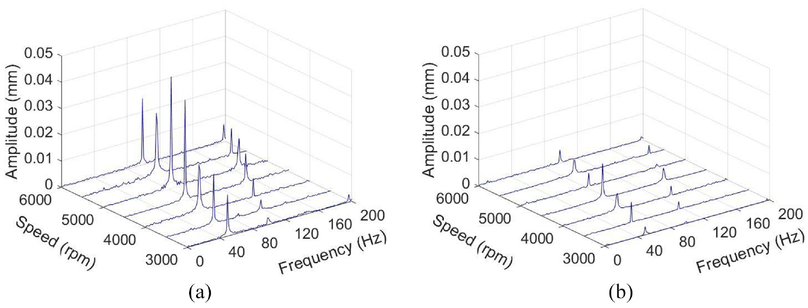
To evaluate the performance of the rotor-bearing system in the run-up process, waterfall plot was used to show how bearing response changes over rotational speed. Schweizer 21 uses waterfall plots simulations to analyze the synchronization of internal and external oil rotation/whiplash that occurs in a fully floating annular bearing. In addition, de Castro et al. 22 used waterfall plots to identify fluid-induced instabilities, which can show the transition from synchronous to sub-synchronous vibrations. The vibration reduction performance of different bearing structures at specific speeds was investigated. Here, the amplitude refers to the shaft center displacement in Y direction. Comparing the two waterfall diagrams in Figure 11, it can be seen that compared with the FPJB, the DL-FSTPB significantly reduces the fundamental frequency (1x) peak amplitude at all speeds. In addition, it can be seen that the first critical speed of the FPJB is about 5000 rpm, and the first critical speed of the DL-FSTPB is about 4000 rpm. This is because the spring structure reduces the comprehensive support stiffness, resulting in the first critical speed of the system has decreased. The waterfall diagrams show that DL-FSTPB can effectively reduce amplitude.

Comparison of waterfall plots: (a) FPJB and (b) DL-FSTPB.
Vibration acceleration wavelet analysis
During the operation of the bearing-rotor system, the disturbance of the journal causes the instantaneous change of the oil film force, and then the oil film transmits the force to the bearing housing, so the acceleration value of the bearing housing can accurately reflect the vibration of the system. 23
Wavelet analysis based on multi-resolution analysis has the advantage of reflecting local signal characteristics more accurately and effectively in time domain and frequency domain. Figure 12 shows the wavelet time-frequency diagram of acceleration signal in the vertical direction and the abscissa is the time when the acceleration signal is collected. The tests were carried out in a steady state within a specific speed range (from 1000 to 6000 rpm at intervals of 500 rpm). In this test, the vibration signals of the two bearing operating speeds near the first critical speed are selected for wavelet analysis and comparison, that is, the wavelet analysis and comparison of 4000–6000 rpm. In Figure 12, the energy of vibration is represented by color, red represents the strongest vibration, green represents about half of the maximum vibration energy, blue is the background value and represent the weakest energy. The energy at the fundamental frequency is larger, and there will be a clear red peak. Vibration levels can be judged by comparing the color at the fundamental frequency that represent the amount of energy. From the wavelet analysis results, it can be clearly seen that compared with FPJB, the fundamental frequency energy of DL-FSTPB at 4000, 5000, and 6000 rpm is significantly reduced, and the fundamental frequency energy peak is almost eliminated at high rotational speeds (5000, 6000 rpm), which reflects the good vibration damping performance of DL-FSTPB.
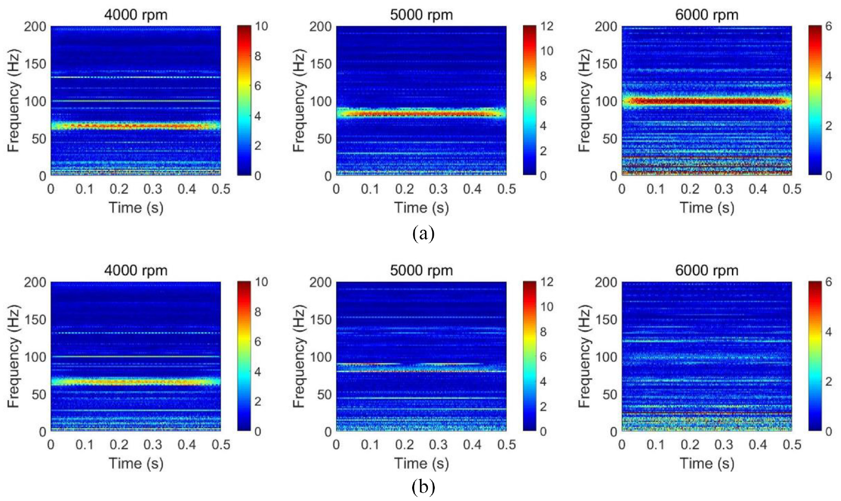
Wavelet analysis of acceleration signal:(a) FPJB and (b) DL-FSTPB.
Displacement amplitude analysis
In order to study the vibration reduction performance of different bearing structures under specific rotational speeds, the dynamical response of rotor at the first critical speeds, 3000–6000 rpm are shown in Figure 13. The time-domain analysis shows how a signal changes over time and shaft center trajectory facilitates the measurement of the rotor movement relative to the static equilibrium position. The results show that the displacement amplitudes of DL-FSTPB are smaller than that of FPJB at each speed, especially at high speeds. It is suggested that compared with FPJB, DL-FSTPB can reduce rotor amplitudes.

Rotor response of two bearings at different speeds: (a) the first critical speed (the first critical speed of FPJB is 5000 rpm, and that of DL-FSTPB is 4000 rpm), (b) 3000 rpm, (c) 4000 rpm, (d) 5000 rpm, and (e) 6000 rpm.
The instability of a plain bearing is proportional to the area of a rotating orbit,24,25 and can be expressed as follows:

In this equation,
The shaft center orbits of the non-driving end of two bearings were compared to further study the stability of different bearings at specified speeds. It is worth noting that the shaft center orbits drawn in this study are full time orbit plots, and elliptical filtering is used. As shown in Figure 13, at 3000–6000 rpm, the shaft center orbits are elliptical, indicating that the bearing is running stably. This study compares the shaft center orbits of the two bearings at the same speed, and the results show that the area enclosed by the elliptical orbits of the DL-FSTPB at each speed is smaller than that of the FPJB. In addition, the shaft center orbits areas of the two bearings at the first critical speed is compared, which shows that DL-FSTPB can reduce vibration, reduce various failures caused by vibration.
Bearing system analysis under loading
In order to further study the vibration reduction performance of the DL-FSTPB under different loads, this study applied a load of 200 N to the rotor system through the loading device. The weight of the rotor system in the previous test is 100 N. The tests were conducted in steady state for a range of specific rotating speeds (from 3000 to 6000 rpm at intervals of 500 rpm).
Comparing the two waterfall diagrams under loading in Figure 14, it can be seen that compared with FPJB, the DL-FSTPB significantly reduce the peak amplitude of the fundamental frequency (1X) and the amplitude of the second frequency (2X) at all speeds. In addition, the first critical speed of DL-FSTPB under loading is 4500 rpm, which is different from the first critical speed (4000 rpm) when DL-FSTPB is not loaded, indicating that the additional 200 N load of the bearing-rotor system changes the critical speed of DL-FSTPB. The results show that DL-FSTPB can still reduce the amplitude of rotor under loading.
Comparison of waterfall plots under loading: (a) FPJB and (b) DL-FSTPB.
As shown in Figure 15, this study compares the shaft center orbits at the same speed and the first critical speed of the two bearings under loading. The results show that the area enclosed by the elliptical orbits of the DL-FSTPB is still much smaller than that of the FPJB, which further verifies the effectiveness of the DL-FSTPB vibration reduction under loading.

Comparison of two bearing shaft center orbits at different speeds under loading: (a) the first critical speed (the first critical speed of FPJB is 5000 rpm, and that of DL-FSTPB is 4500 rpm), (b) 3000 rpm, (c) 4000 rpm, (d) 5000 rpm, and (e) 6000 rpm.
Conclusions
An experimental evaluation of the study of vibration reduction performance of the novel DL-FSTPB was carried out. The conclusions are as follows:
(1) In this paper, a novel double layers flexible support tilting pad bearing (DL-FSTPB) is proposed. The bearing utilizes two layers of springs, which have different functions. The offset springs enhance the hydrodynamic wedge, and the symmetrical springs is used to change the bearing stiffness coefficient, increase the bearing elasticity.
(2) The time histories of journal displacements and time domain waveforms are used to further analyze rotor dynamic performance in the run-up process. Compared with FPJB, the DL-FSTPB can not only reduce the fundamental frequency vibration(1X), but also reduce the triple frequency component (3X). It shows that compared with FPJB, DL-FSTPB can effectively reduce the amplitude at the first critical speed.
(3) Waterfall plot results can be seen that compared with FPJB, the DL-FSTPB significantly reduces the peak amplitude of the fundamental frequency (1X) and double frequency (2X) at all speeds. In addition, the first critical speed of the FPJB is about 5000 rpm, and the first critical speed of the DL-FSTPB is about 4000 rpm. The structure of the spring reduces the comprehensive support stiffness, resulting in the first critical speed of the system has decreased.
(4) Comparing the acceleration wavelet analysis results of the two bearings at 4000, 5000, and 6000 rpm, it can be seen that compared with FPJB, the fundamental frequency energy of DL-FSTPB is significantly reduced, and the fundamental frequency energy peak is almost eliminated at high rotational speeds (5000, 6000 rpm), which greatly reduce the system vibration level.
(5) Measurement and mapping of the shaft center orbits to assess the operation stability of different bearing structures under specific rotational speeds. The results show that the area enclosed by the elliptical orbits of the DL-FSTPB at each speed is smaller than that of the FPJB, especially at high speeds. In addition, the shaft center orbits area of the DL-FSTPB at the first critical speed is smaller than that of the FPJB, which further verifies the effectiveness of the DL-FSTPB for vibration reduction.
(6) Finally, the vibration of the two kinds of bearings under different loads are experimentally analyzed. By analyzing waterfall plots and shaft center orbits, it is shown that the first critical speed of DL-FSTPB becomes 4500 rpm under loading, which means that the additional load added to the rotor system changes the dynamic characteristics of the oil film, resulting in the change of the first critical rotor speed. And the DL-FSTPB can still effectively reduce the amplitude of acceleration and displacement.
Footnotes
Handling Editor: Chenhui Liang
Declaration of conflicting interests
The author(s) declared no potential conflicts of interest with respect to the research, authorship, and/or publication of this article.
Funding
The author(s) disclosed receipt of the following financial support for the research, authorship, and/or publication of this article: The research work described in the article was supported by the National Natural Science Foundation of China (no. 52075311) and Shanghai Key Laboratory of Intelligent Manufacturing and Robotics.
Data availability
All data included in this study are available upon request by contact with the corresponding author