
Abstract
The operation of gas generators brings relatively high thermo-mechanical loads on the gas generator structure. The objective of this article is to determine the operating conditions, in terms of mechanical loads at extremely high temperatures in very limited and narrow space, of a multifunctional bulkhead for application on specific kinds of gas generators with back-to-back rotor concept. The paper contains numerical analysis and experimental investigation for determining the loads and behavior of the structure. Numerical analysis indicates that there is significant influence of the Tesla turbine effect on flow parameters. Also, uneven pressure distribution and significant thermal loads are identified. With experimental investigation and subsequent exploitation tests, it was concluded that the presented methodology identifies the operating conditions, truthfully simulates the bulkhead stress state and deformations and that the presented design solution satisfied all demands. Regarding results obtained by these numerical simulations, the innovative design solution for the multifunctional bulkhead was proposed.
Keywords
Introduction
For gas generators there are distinctive, extremely hard operating conditions where the mechanical structure is loaded by a complex interaction of mechanical loads, thermal loads together with extremely high heat phenomena, no homogeneous influences, intensive influences of fluid flow, high rotation speeds, its natural and forced vibrations etc. The primary thermal process in engines or gas-generators is the process of fuel combustion which is more efficient if it occurs with compressed air. In Benini and Giacometti, 1 a design of a turbo-jet engine is presented where the gas from the combustion drives the turbine together with the compressor at the speed of 60,000 rpm and produces jet force. For this design a CFD analysis of air streaming in the compressor section is performed, with the aim of obtaining the air velocity distribution and pressure rate in relation to mass flow and speed of rotation. The subject of the research in Guo et al. 2 is also the streaming process in the centrifugal compressor with the objective to optimize the shape and to reduce the number of vortices in the stream flow. Similar CFD analyses for transonic centrifugal compressor and capillary diffuser are done in Zamiri et al., 3 Yuvaraj et al., 4 and Zhao and Li. 5 In our study, a numerical CFD analysis is used to identify fluid velocity and pressure distribution including the heat interaction between the fluid and the structure. Fuel combustion can produce a significant thermal effect on the total load level. Detailed CFD analysis of the thermal effect at the rocket nozzle is analyzed in Zivkovic et al. 6 Jet tabs of the nozzle for rocket flight control are significantly thermally loaded. Temperature distribution and heat transfer are identified in order to find out the solution to prevent material degradation of nozzle tabs. Thermal loads of the nozzle are also the subject of Haiyang and Qiang. 7
Thermal effects together with fluid effects (pressure and velocity) and mechanical loads produce extreme operating conditions of the mechanical structure of the gas generators. The most vulnerable machine part is the turbine blade. Very high centrifugal forces, non-uniform and high fluid pressure and very high temperature cause various kinds of blade failures. These are the cracks arising together with material degradation.8,9 Some researches show that thermal stress can be higher than mechanical. The temperature of the crucial parts, such as the turbine, directly influences the service life of the entire system. Therefore, to prevent these thermal stresses, a heat shield in form of coatings is introduced. Sadowski and Golewski 10 presents an analysis of the influence of single ceramic thermal barrier coating on temperature distribution through the material of the blade in order to increase the temperature level of operation fluid or to improve the temperature resistance of the aircraft engines. Another paper 11 shows that increasing the thermal coating thickness to 300 µm leads to an increase of blade life by 9 times. The most mechanically loaded part of the gas generator is the compressor. It is exposed to high centrifugal loads, non-uniform pressure distribution, fatigue in the areas with stress concentration, 12 natural frequencies of its blades, 13 etc.
The presented loads which are a combination of mechanical, fluid and thermal effects, are much more unfavorable in the new design structure of the gas generator for application in the turbo-jet and turbo-shaft engines of the back-to-back type. In order to increase efficiency and to reduce volume, the radial compressor and radial turbine are embedded in back-to-back position. The compressor and turbine space are divided by the stationary bulkhead set in a very narrow space. The space of the bulkhead is characterized by very high gradient of temperature, fluid streaming speed and pressure, that is, extreme operating conditions. The subject of this article is the identification and analysis of the operating conditions and development of a bulkhead structure, suitable for operation in these extreme conditions. In the state-of-the-art literature, no papers could be found related to such a case study, multifunctional bulkhead, because it refers to back-to-back concept of gas generator which is very rare. But its operating conditions and complex load state have some similarities with structures in the previously cited papers. In the previous publication, Kolarević et al. 14 explained the problems occurred during the development of the structure of the multifunctional bulkhead together with causes and failures during the experimental investigations. Numerical identifications of bulkhead operating conditions for several previous design versions used for Failure-based Design approach in the multifunctional bulkhead design are also presented in the cited article. More detailed information can be found in the research related to PhD thesis. 15
In this paper a steady state two component gas flow analysis was carried out in order to provide the information about pressure and heat convection coefficient distribution along the bulkhead external and internal surfaces. The thermal numerical module was used for defining the body temperature which represents the thermal load of the structure. At the end, a structural analysis of thermo-mechanical loads of the structure, pressure and body temperature, was carried out in order to predict the stress state and behavior of the multifunctional bulkhead. Similar CFD-FEA coupled approach can be found in Refs.10,11,16,17
In this paper the influence of other specific effects, such as erosion failure mechanisms, 18 hot corrosion, 19 oxidation, 8 wear, fouling, 20 thermal fatigue 9 and others are neglected due to two major reasons. First, the numerical model is already very complex and it demands considerable time and hardware resources. On the other hand, the idea is to determine the actual operating conditions for this specific multifunctional bulkhead and based on that to provide the design solution which will satisfy the demands for short lifetime engines used for unmanned aircrafts. Multifunctional bulkhead is part of the engine that has extreme operating conditions in terms of mechanical loads (pressure and preload) of the structure at very high temperatures in very limited and narrow space. The problem how to make a satisfying design solution that settle previous contradictions, to withstand loads and to direct deformations in available area while retaining main functions, come up to be a very complex during development of gas generator prototype.
Multifunctional bulkhead functions and design
The gas generator produces gas of high pressure which, by combustion and expansion, can drive turbines or produce jet force. Fuel combustion needs air under high pressure. For the compressor drive it is necessary to install the gas turbine at the same shaft with the compressor. This turbine can have two functions: just to drive the compressor or, apart from that, to produce output torque by transforming the complete combustion energy as in the turbo-shaft engine. If the turbine drives only the compressor, its disk diameter is usually smaller in comparison to the compressor disk. If the turbine transforms the complete energy of combustion, its disk diameter is larger than the compressor disk diameter. The compressor and turbine disks are seated at the same shaft close to each other in relation back-to-back. 21 The gas generator consists of the following sections: intake, compressor, diffuser, combustion chamber, turbine stator, turbine rotor, nozzle and multifunctional bulkhead sections (Figure 1).
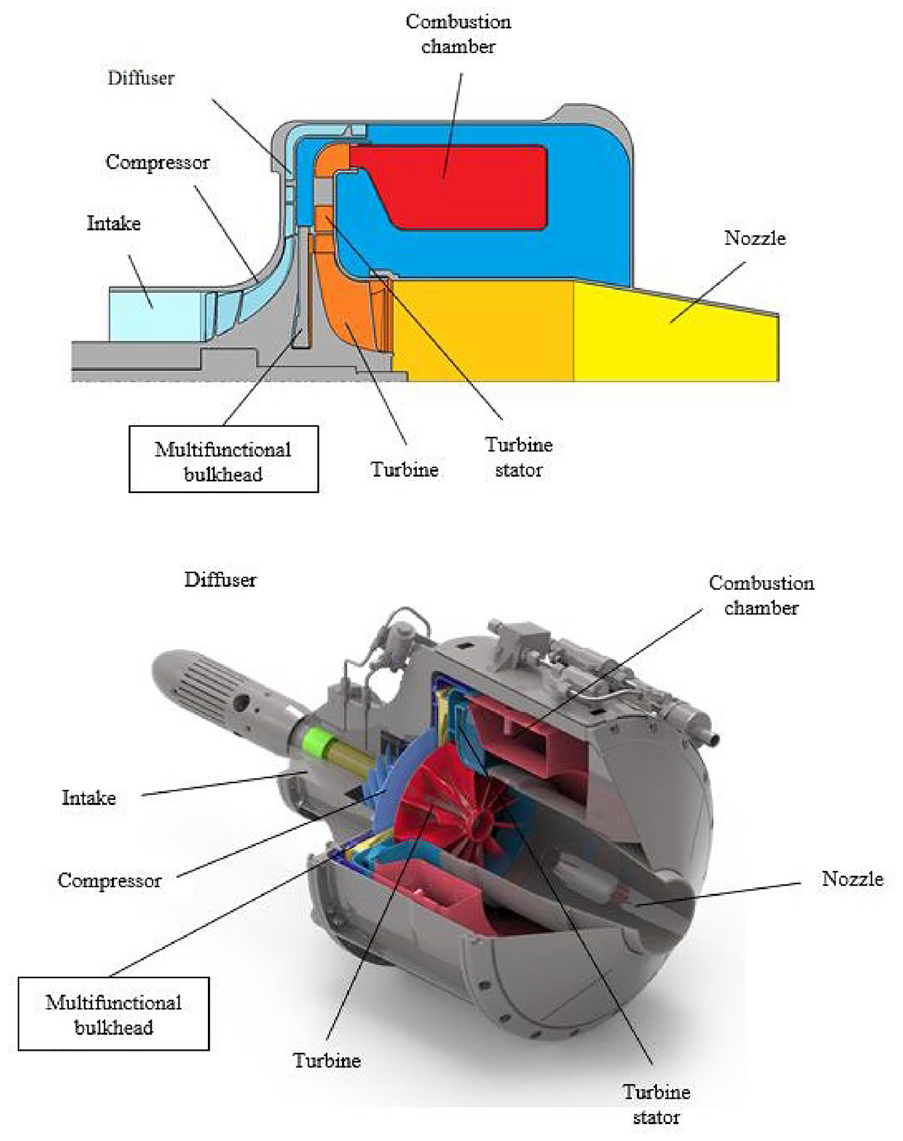
Main sections and gas generator.
Multifunctional bulkhead presents the structure barrier between relatively cold compressor section of the engine and hot turbine section of the engine. Bulkhead is stationary part, installed between compressor and turbine, splitting these sections in every sense. The bulkhead has several functions and that is why it is called multifunctional. The first function of the bulkhead is related to the thermal protection of the compressor. The compressor is made of light titanium aluminum alloy which is not suitable for withstanding high loads at increased temperatures. Unlike the compressor, the turbine is made of Inconel super alloy and operates at very high temperatures (around 700°C). Therefore, it is necessary to prevent the influence of high temperatures from the turbine zone onto the compressor, which is achieved by the multifunctional bulkhead. Another function is to prevent the operation fluid leakage from the higher pressure in the cold compressor zone to the lower pressure in the hot turbine zone. To explain the third function – the axial force reduction, the origin of that axial force will be explained first. As the turbine is designed only to drive the compressor, its diameter is smaller than the compressors. Compared to the turbine, the compressor operates at a higher pressure of the operating fluid. Taking these two facts into account, it is concluded that there is a large axial force generated due to pressure distribution on the rotor assembly (the higher pressure on the larger compressor disk surface creates a bigger force component in the axial direction than the smaller pressure on the smaller turbine disk surface in the opposite direction). This large resultant axial force drastically increases the load on the bearing assembly. The reduction of this bearing load is the third bulkhead function. The last important role is the injection of the cold air onto the turbine disk, thus cooling the turbine root area in order to prevent high reduction of yield stress caused by temperature rise. More details about bulkhead functions could be found in Kolarević et al. 14
The design of the multifunctional bulkhead that encompasses all four previously explained functions, presents a very complex task, especially if one takes into account the very narrow space for bulkhead installation and its position in the gas generator. The space has to be as narrow as possible in order to reduce the distance of the overhanging mass that affects the rotor dynamics, bearings and clearances. The minimal distance of the overhanging mass and demands of the rotor dynamic, as well as aviation application, do not also allow any robust construction. By using the iterative approach together with the experimental investigation and calculations, the multifunctional bulkhead design solution is developed and presented in Figure 2. The structure consists of two parts, the first one highly rigid to withstand the pressure load and the other, which is supposed to act as a heat shield by absorbing thermal radiation from the turbine. Therefore, the multifunctional bulkhead assembly consists of a relatively massive supporting plate and an elastic sheet metal called the elastic plate.

The design solution of multifunctional bulkhead. 14
The supporting plate is made of stainless steel X17CrNi16-2 (1.4057) and carries two labyrinths, axial and radial. In order to reduce the resulting axial force on the engine rotor, the axial labyrinth provides the first sealing stage, that is, pressure drop. The second, the main sealing stage, is obtained by the radial labyrinth which is pressed into the central hole of the supporting plate. To decrease the static pressure which acts on the compressor disk as much as possible, holes were drilled through the compressor (blue arrow line in Figure 2). These holes, drilled from the compressor’s hub to its back, create an effect of pulling out the air from the area between the labyrinths, and thus reduce the static pressure value, consequently reducing the resulting axial force on the engine rotor. To obtain the best performances, the labyrinths should be mounted at very low operating clearances (0.1–0.2 mm). Having that in mind, in order to prevent the clash between the axial labyrinth and the compressor disk, the supporting plate has to be highly rigid.
The elastic sheet metal part is attached to the supporting plate by the stainless steel screws. The screw connection can be replaced with a welding joint, but in this case, a dismountable connection is desirable. This elastic part has an unconstrained outside diameter which is fully free to deform by absorbing heat. Due to the exposure to high temperatures up to 800 K, the elastic part has to be made out of a special material, as it is Inconel 718 sheet metal 0.8 mm thick. It has a bended, S-shaped cross section in order to withstand the pressure difference from both sides and to press on the turbine stator surface so as to seal the inside space (Figure 2). In order to cool the turbine and reduce the axial force on the rotor assembly (blue arrow in Figure 2), the cold air at the higher static pressure is injected from the area around the combustion chamber, after the diffuser with relatively cold pressurized air, through the radial holes in the supporting plate. Afterward it flows through the holes in the elastic plate drilled in the vicinity of the screws which connect the elastic and support plate, cooling this way the root of the turbine disk. The dimensions of each part come from a few iterations of numerical calculations of the temperature field, stresses, and deformations.
Numerical analysis of thermo-mechanical loads, deformations and stresses
To transform an idea into a real construction, initial dimensions must be defined. As the multifunctional bulkhead is a very specific part, a few numerical analyses were conducted in ANSYS software. To determine the operating conditions, it is necessary to conduct a CFD (Computational Fluid Dynamic) calculation which will provide the distribution of pressure and heat on bulkhead surfaces. Then, with the thermal module, based on the finite element method, the temperature of every point in the bulkhead structure can be calculated. The thermal state with pressure distribution on the bulkhead structure, together with the necessary constrains, are enough for the steady state numerical model for determining stresses and deformations. On one hand, the stresses must be on a satisfying level whereas on the other hand, there is a much stricter demand for the rigidity and deformation. Because of the very high temperatures in the cavity around the bulkhead, yield strength of materials is significantly reduced, and no plastic behavior is permitted. The bulkhead should not get in contact with the rotor through the entire engine operating regime, and due to the proximity to the rotary parts, the deformations must be very small. This is especially important in the labyrinth zones, where the clearance between the bulkhead and the compressor counts 0.1–0.2 mm. Of course, with these mechanical demands all the above mentioned functions must be completed to provide an undisputed gas generator operation with high performances and satisfactory service life.
The CFD numerical model for simulating the flow of operating fluid, through engine sections explained above, is defined by using a combination of CFD and FEM calculations through several iterations in order to determine the operating clearance between the rotor and stator parts (neglecting some axial deformations of the compressor) and to determine the operating temperature of the rotor parts, Figure 3. With each iteration, the geometry of the mentioned clearances is corrected to the new values, which are lower than the mounting clearances, with regards to the deformations of the engine rotor parts. These deformations of the compressor and turbine, mostly due to centrifugal force and heating, are determined through a combination of FEM Steady State Thermal and Static Structural analyses, as shown on the right side of the flow chart in Figure 3. Within each step of this iterative process, the temperatures of the compressor and turbine surfaces, that are in contact with the fluid around the multifunctional bulkhead, are monitored and corrected in next CFD simulation. This temperature rise at mentioned surfaces is a consequence of heating the rotor parts along their hubs and blades with operating fluid. Temperature distribution along disk surfaces of the radial compressor and turbine facing the multifunctional bulkhead, see Figure 2, is obtained to be more or less uniform mostly due to good heat conduction through the material. So, the heat transfer models in the CFD simulation for boundary rotating surfaces of the cavity around multifunctional bulkhead, that represent rotor surfaces of the multifunctional bulkhead section, consist of fixed temperatures on the compressor side of 490 K and the turbine side 830 K. This part of the simulation for defining the clearances and rotor surfaces temperatures is not present in the paper due to the massiveness of the entire numerical model.
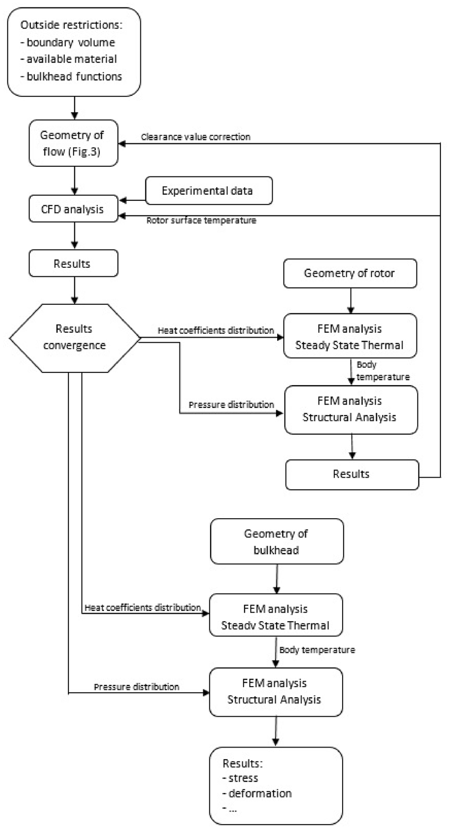
Flow chart that illustrates entire procedure of numerical simulations and their relations.
After defining the operating clearance between the rotor and stator parts, and temperatures of rotor surfaces, the last CFD iteration is done and its result of heat coefficients distribution is imported into the FEM Steady State Thermal Analysis for calculating the body temperature of the bulkhead. Pressure distribution from CFD analysis and body temperature from thermal analysis are input parameters for the Static Structural Analysis of the multifunctional bulkhead, that is, these results are loads for the structural analysis. The transfer of results from CFD to FEM is done by an internal solver in ANSYS software by interpolations between adjacent points of the calculation mesh of the CFD and the corresponding calculation mesh of the FEM models.
Because of the unapproachable space in the cavity around the bulkhead, very narrow space with clearances of below 1 mm and high temperature and velocity of the operating fluid, it was impossible to measure any flow parameter, including near-wall convection coefficients, to validate the numerical model in this cavity. The validation is done with a global model, comparing the simulated results of flow parameters and values obtained by measuring devices on a certain place on the engine on the test and due to the fact that the structure behavior is as expected by simulation which is confirmed by visual inspection of parts after experiments and exploitation of the engine.
Fluid stream analysis
Because of its location in the center of the gas-generator and dimensions, there was no possibility to experimentally determine the flow parameter in the cavity around the multifunctional bulkhead, so a numerical model of the entire engine is created.
In order to achieve a good detailed mesh for the boundary layer that can simulate a flow with high quality around the blades and near the walls in areas of interest with a number of mesh elements that commercial hardware (work stations but not supercomputers) can calculate within some acceptable time limits, geometry is reduced to a 40° cut-out of the cold section (one ninth of the full section) and 60° cut-out of the hot section (one-sixth of the full section). It consists of three main segments: cold, hot and multifunctional bulkhead sections. The cold part simulates the flow at relatively low temperature through intake, compressor and diffuser. Air ideal gas as an approximation for operating fluid is accepted. The inlet boundary condition of the cold section, on the gas generator intake, is given as mass flow of dm/dt = 0.094852 kg/s that corresponds to 1/9 part of the cut-out with total temperature Ttot = 299 K, while the outlet condition, after compressor stator – diffuser, is defined with static pressure of the p = 365,800 Pa. Inlet mass flow and outlet static pressure are defined by compressor characteristics on presented operating regime at 54,621 rpm in the section 4, while the total temperature can be assumed from the ambient conditions during the test. The hot section includes the turbine stator, rotor and nozzle. The air ideal gas with parameters at the temperature of combustion product (cp = 1132 J.kg−1.K−1 and molar mass of 29.29 kg mol−1) is used as an approximation for mixture of hot combustion products. The annular combustion chamber is located between the cold and hot sections in the real construction, but in this numerical model it is left out due to its complexity to simulate. Its influence is taken into account with a total pressure drop of 4%, which is a usual and expected value for such combustion chambers. So, the inlet of the hot section is on the turbine stator surface that is the outlet from combustion chamber and its boundary conditions are defined with increased mass flow for the amount of fuel burned at presented regime dm/dthot = 0.144278 kg/s that corresponds to 1/6 part of the cut-out and total temperature approximated with the measured value of total temperature measured on the nozzle of Ttot = 970 K. The outlet is defined at the nozzle with static pressure p = 97,000 Pa calculated from the measured total pressure at the nozzle with separate and special system. The geometry and numerical model with boundary conditions are shown in Figure 4. This numerical CFD model is two-component flow simulation. Heat transfer is computed with included viscous work and Total Energy option. Shear Stress Transport (SST) turbulence model is used with High Speed (compressible) Wall Heat Transfer model, Automatic Wall Function and Turbulent Flux Closure for Heat Transfer with corresponding y+ value of 80. The numerical model consists of seven domains, two inlets, two outlets, one opening, periodic and contact interfaces and other boundary conditions. The calculation mesh for the entire numerical model for fluid stream simulation is made from tetrahedrons elements because we were not able to achieve hexahedral elements within some special modules for CFD meshing. The reason for this failure is the horizontal hole that connects the domains of the multifunctional bulkhead and compressor, Figure 4. So, we were forced to produce the mesh for the entire model with 14,000,000 elements in order to achieve satisfying results convergence. It is more detailed around the blades and near rotational surfaces of the turbine and compressor. Graphical representations of the numerical solution for flow through gas generator with pressure and temperature distribution on static surfaces of the multifunctional bulkhead are shown in the following Figures 5 and 6.

The numerical model and its geometry, an entire gas generator cut-out that consists of three main segments: cold (blue), hot (red), and bulkhead (yellow).
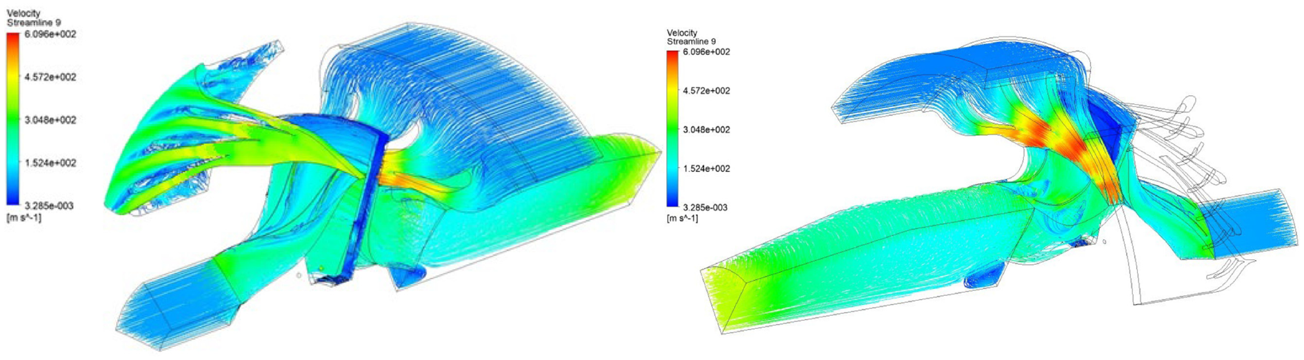
Streamlines presentation through cold and hot section of engine with pressure distribution contour in cavity section.

Static pressure distribution on the left and temperature contours on stationary surfaces of multifunctional bulkhead assembly on the right.
For boundary data and verification of the model, data from experimental testing is used (section 4). The measured values and values obtained by simulation coincide within 5%, which is quite acceptable from the engineering point of view. The measuring points and obtained values are shown in Figures 17 and 18 in section 4. Engine rpm of 54,621 is set as boundary condition for the walls that rotates as compressor and turbine disks and hubs. On the inlet of the intake, where atmospheric conditions of pressure 101,100 Pa and temperature 299 K (measuring point 1) were present on the testing day, numerical model gives following values of pressure 100,467 Pa (99% coincide) and total temperature 299 K (100% coincide). On the exit of the cold section, at the diffuser outlet (measuring point 2), measure value of absolute static pressure is 365,800 Pa while the simulated obtained value is 365,013 Pa (99% coincide). On some later tests, under pressure sensor was installed on the intake section and by hand calculation it was assumed that mass flow rate of air is around 0.9 kg/s, while simulated value is 0.86 (96% coincide). Measured values on the engine testing at the nozzle exit (measuring point 3) are total pressure 150,000 Pa and static temperature 743 K, while simulated values are 144,383 Pa (96% coincide) and 716.8 K (96% coincide).
Streamlines have significant flow separation because the angle and positions of the diffuser and turbine blades are optimized for engine operation at 62,000 rpm. As simulation is done on 54,621 rpm, blades do not have the optimal geometrical shape for this value of rotation and this can be seen from Figure 5. The model confirms the assumption of pulling out the air from the cavity between the compressor and multifunctional bulkhead. Also, the model confirms the assumption of cooling the turbine with relatively cold air injected through the holes in supporting and elastic plates of the multifunctional bulkhead assembly. This cannot be seen clearly from streamlines in Figure 5, but the temperature uneven distribution around the cooling holes in Figure 6 clearly indicates that. On the side toward the compressor, due to the narrow gap between the support plate and the compressor disk, the pressure distribution decreases in radial direction – inward. The pressure drop is especially noticed in the area between the compressor back surface and multifunctional bulkhead, especially between axial labyrinth and the compressor where the gap is the smallest (0.1–0.2 mm). This phenomenon occurs due to the Tesla turbine effect,22–26 which is more emphasized if the gap between the rotating component (compressor) and stationary component (support plate) is smaller. In the cavity on the turbine side, pressure distribution is much more uniform because of the significantly greater air gap between the elastic plate and turbine disk, that is, the influence of the Tesla turbine effect in this area is negligible. However, the influence of the cooling air on the average pressure in this area is significant due to injection of relatively cold air at the higher pressure. There is a temperature rise on surfaces of the elastic plate due to heat radiation from the turbine and that is taken into account in later Steady-State Thermal numerical model.
Steady State Thermal and Static Structural analysis are done for rotor parts such as the turbine and compressor in order to define the clearance between the impellers and their stators, that is, to determine operating air gaps at the mentioned gas generator regime, Figure 3. These gaps are the interface (boundary condition) between the multifunctional bulkhead domain and compressor domain from one side and the turbine domain from the other side. This part of the procedure is done iteratively with CFD analysis and it is not presented in this paper due to the massiveness of the entire numerical model for determining the operating conditions of the multifunctional bulkhead. Something similar is done in Kim et al. 27
The mesh independence is carried out to ensure the valid values of pressure and temperatures obtained by solving the numerical model at the previously described measuring points. The first mesh is done with 4,000,000 elements, the second with 7,000,000 elements and the last with 14,000,000 elements. The third one has a significantly larger number of mesh elements due to the fact that slight increase in density of the mesh around the blades, where the effect of boundary layer on flow parameters is significant, leads to a large increase in the number of elements as there are a lot of blades and such surfaces. The dependency of values of the pressure and the temperature, in the places that correspond to measuring points on the experimental test, with the number of mesh elements are shown in the following Figure 7.

Mesh independence analysis with pressure and temperature values in the areas that correspond to measuring points at experimental testing.
Heat distribution and temperature field analysis
Near wall convection coefficient, from CFD calculation on static cavity surfaces which represents solid-fluid interface, is inputted in the Thermal module, Figure 3. The influence of heat radiation from the turbine rotor is inputted separately into the same model as additional heat flow, Figure 8.

Numerical thermal module for multifunctional bulkhead with its boundary conditions.
The results of the thermal numerical model provide the information of temperatures in each point of the structure of the multifunctional bulkhead assembly. The results show that the elastic plate absorbs the heat from the turbine, and is subjected to very high temperatures of around 800 K. As it is made from Inconel 718 sheet metal, this high temperature does not cause any significant problem, since this material has good mechanical properties until temperatures of 1000 K. The supporting plate operates mostly at the temperature of 600 K, and it cannot be significantly decreased, since the compressed air coming from behind the diffuser, has a similar temperature. The results of body temperature (Figure 9) are imported in Static Structural module to analyze stress state and deformations of the structure.

Results of body temperature for multifunctional bulkhead.
Bulkhead stress and deformation
From the CFD solution a non-uniform pressure distribution on multifunctional bulkhead assembly surfaces was imported in the Static Structural module, and it is shown in Figure 10.

Pressure distribution results on surfaces of bulkhead assembly imported from CFD module, side toward compressor on the left and side toward turbine on the right.
The previously described thermal load combined with the pressure load creates total structure thermo-mechanical load during engine operation at 54,621 rpm. This total load with adequate constrains, Figure 11, creates the numerical model for stress and deformation analysis of the structure. The supporting plate of the multifunctional bulkhead assembly is positioned in the gas generator along the diffuser with cylindrical surface, shown in blue color in Figure 11 (constrain A), and with front surface shown in yellow color on the same figure (constrain B). For constrain A, a cylindrical support type is used because it permits the elongation of the plate as its temperature increases, while constrain B removes the axial displacement of the plate. Elastic plate is preloaded with the turbine stator, in order to retain the sealing contact during operation, by deforming the yellow surface in axial direction for the negative value of 0.8 mm (constrain C). The approximation of bonded connection between the support and elastic plate is used for simulating the bolt connection in order to simplify the numerical model. So, the structural numerical model of the bulkhead has limitations of movement only to surfaces where the assembly is supported to the compressor stator-diffuser (constrains A and B) and on the turbine stator (constrain C) as shown in Figure 11. As the bulkhead is a stationary part of the engine there are no inertial loads due to rotations, only the preload of the elastic plate, pressure distribution and body temperature are the loads of the structure.

Constrains and connections of the structural numerical model of the multifunctional bulkhead.
A material X17CrNi16-2 (1.4057) stainless steel is used for production of the supporting plate, and an alloy Inconel 718 is used, in the form of sheet metal, for production of the elastic plate by bending on press. The material properties, obtained from the manufacturer, are given in Figures 12 and 13, and these values are inputted into the software.

X17CrNi16-2 (1.4057) stainless steel properties.
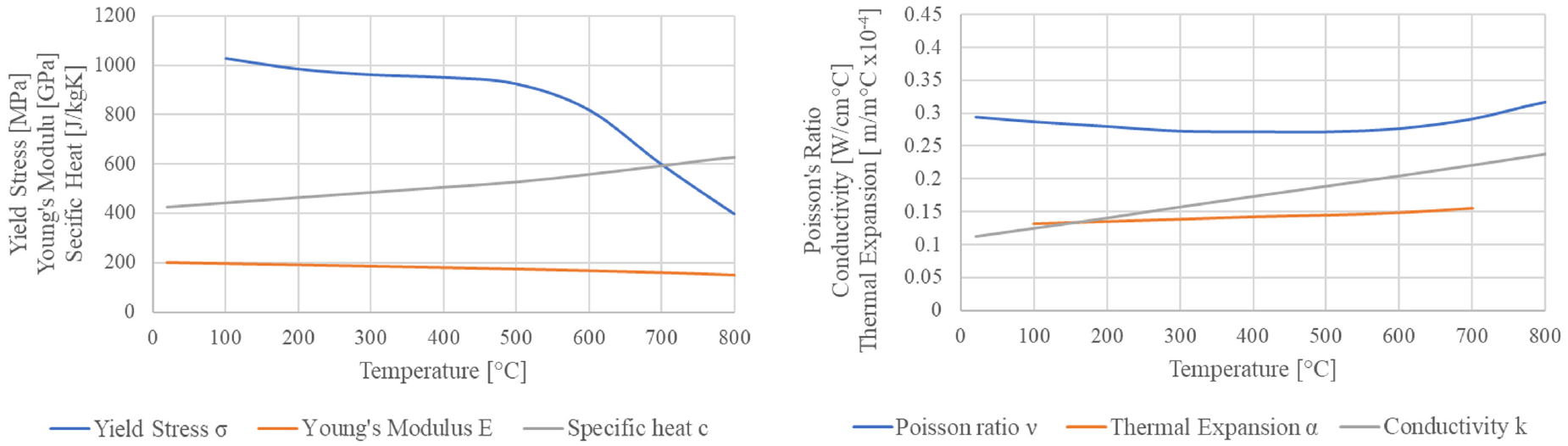
Inconel 718 properties.
The result of the stress-deformation analysis is graphically presented in the Figures 14 and 15 from which one could see that real stress values are not larger than 300 N/mm2 on the elastic Inconel sheet metal and 150 N/mm2 on the supporting plate, although there are some much higher erroneous values on some elements due to the proximity of the constrains. As the 0.2% yield strength of X17CrNi16-2 (1.4057) stainless steel used for supporting plate is 385 N/mm2 at reference temperature, the safety factor has a satisfactory value of around 2.6. In the zone bellow the curvature of the elastic plate, equivalent stresses are around 250 N/mm2 at the temperature of 400°C. The material of the elastic plate is Inconel 718 alloy which has the 0.2% yield strength of Rp0.2(400°C) = 951 N/mm2, so the safety factor in this zone of the elastic plate is 3.8. At the largest diameter of the elastic plate, stresses are lower than 150 N/mm2 but temperature is the highest 500°C. The yield strength of Inconel at this temperature is Rp0.2(500°C) = 910 N/mm2, so the safety factor in this zone is 6.1. Third critical area on the elastic plate is around its inner diameter in the zone of connection with the supporting plate where the stress level is much higher with values above 300 N/mm2, but at the lowest temperature (300°C) due to presence of the cooling air. The yield strength of Inconel at this temperature is Rp0.2(300°C) = 962 N/mm2, so the safety factor in this zone is 3.2. This is the smallest value of the safety factor so this zone is the most critical compared to other areas of the elastic plate. In the future design it is necessary to analyze this zone in more detail and with adequate simulation of the bolt connection effects between the supporting and elastic plate.
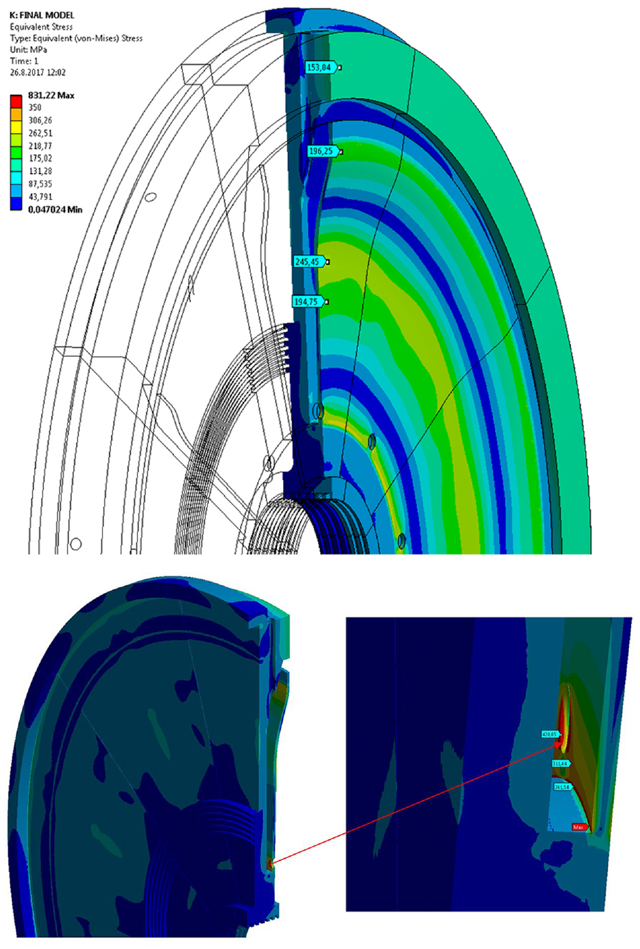
Von-Misses stress state of multifunctional bulkhead assembly.
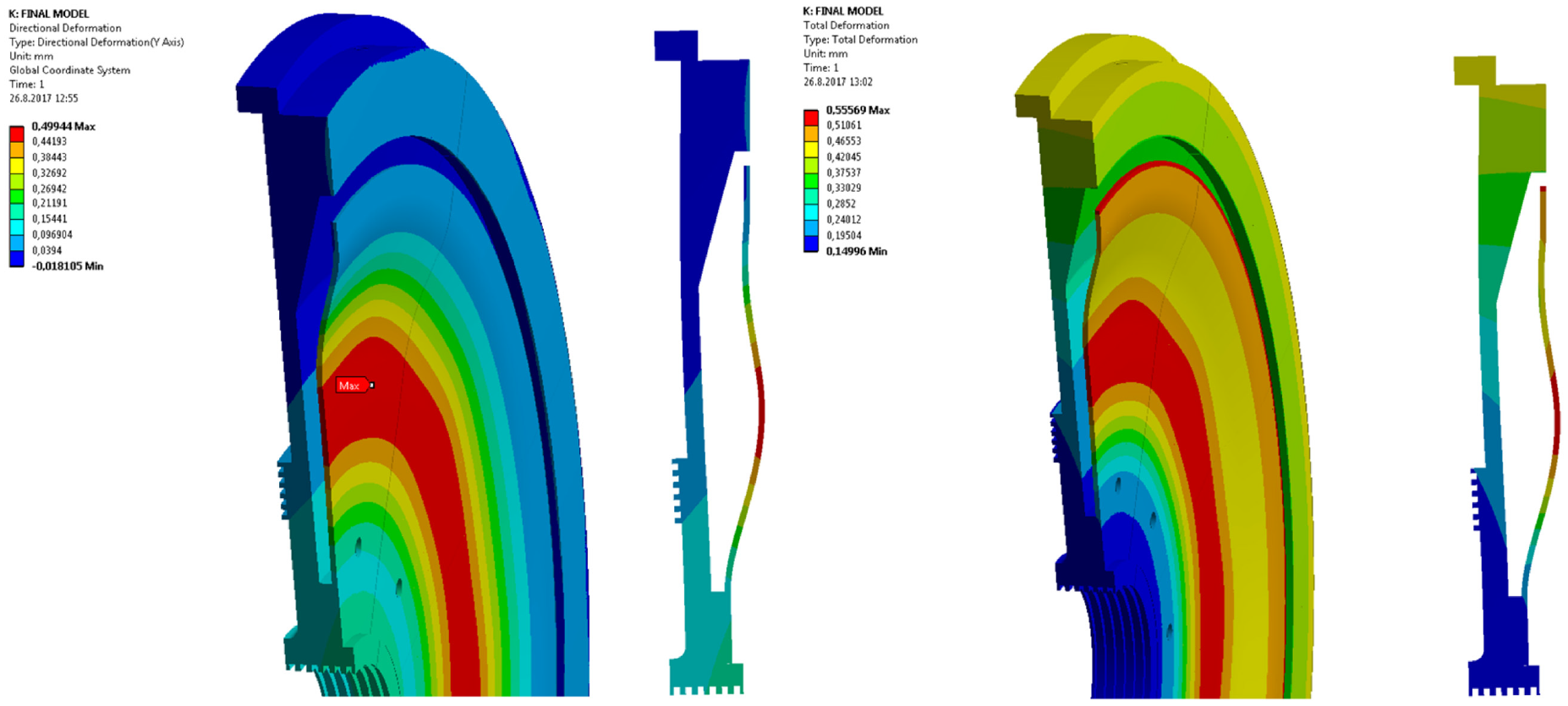
Axial and total deformation of multifunctional bulkhead assembly structure.
The safety factor for the supporting plate is large but labyrinth’s demands for clearances make rigidity more important. Scaled radial and axial deformations in the proximity to the labyrinths are shown in Figure 16, and it can be seen that axial and radial deformations are within permissible boundaries in the sealing area, below 0.2 mm governed by the labyrinth.

Scaled radial deformations above and axial deformation bellow of the multifunctional bulkhead with some representing values around labyrinths.
From the previously mentioned, it could be concluded that simulations provide satisfactory results for multifunctional bulkhead assembly behavior. Since its stress and deformation levels were within permissible boundaries and with tendency to fulfill all desired functions, the assembly was produced and experimentally tested.
Experimental analysis
The cavity around the multifunctional bulkhead is very narrow and placed in the center of the entire gas generator, so it leaves no space for installing measuring instruments. Thus, there is no way to simulate the flow just in this area. The only way to discover flow behavior in the contemplated space and operating conditions of the multifunctional bulkhead is to simulate the flow through the entire engine, so it can be validated with values measured by the acquisition system in certain points during experimental testing of the gas generator. If the measured values are close enough to the results obtained by the numerical model, it can be concluded that the simulation is truthful enough. Then, the flow in the cavity around the multifunctional bulkhead can be used to determine thermo-mechanical loads on the structure. Thus, the experimental analysis is crucial for validation of the CFD calculation and measured values on the gas generator intake, diffuser and nozzle exit areas are used for numerical model boundary conditions, inlets and outlets data.
Laboratory testing
The gas generator is tested independently, with the nozzle, as the turbo jet engine to determine its operating parameters and performances. The following Figure 17 shows the engine on a test bench together with the acquisition system during one of the tests. The acquisition system for the gas generator testing consists of the following sensors: flow meter, accelerometers, several thermocouple probes, two pressure transducers, inductive sensor and load cell.

Acquisition system for engine testing and monitoring.
The flow meter device is installed on the fuel pump and it is used to measure the mass flow rate of the fuel for ignition and the main fuel supply system. It is a part of the engine monitoring and control system. The accelerometers, placed near the bearings, are used to monitor the engine behavior during the tests and to provide the information of the quality of the rotor balance. Also, they can determine resonant areas or appearance of damage. Three thermocouple probes, OMEGA K-type thermo couple CH+ AL−, are installed. The first one reads the temperature of the more loaded bearing set, the second one measures the temperature of the other bearing set, while the third one measures the temperature of the mixture of combustion products and it is placed on the nozzle near its exit section. Two pressure transducers measure the maximum static pressure in the engine, in the area behind the diffuser and before the combustion chamber entrance, and the total pressure on the nozzle with corresponding pipe system for lowering the temperature of the gas. Therefore, the first pressure transducer gives the information of compressor pressure ratio during testing. The pressure and temperature of the ambient environment are measured independently. For determining the engine rpm, the inductive sensor DW-AD-405-04-290 is used. The measuring is executed by means of the toothed distant bush located in front of the gas generator shaft with the previously explained probe. OMEGA S shaped load cell LC111-250 is used to measure the engine thrust during testing together with the appropriate level system installed on the test bench.
The engine test on 54,621 rpm was done successfully with the new design of the multifunctional bulkhead, which represents the result of a studious approach to a structure problem and numerous calculations: CFD, CSM, hand calculations etc. The following Figure 18 presents a diagram with measured values of some basic engine parameters at 54,621 rpm during prototype testing, except the total pressure which was measured with a separate system.
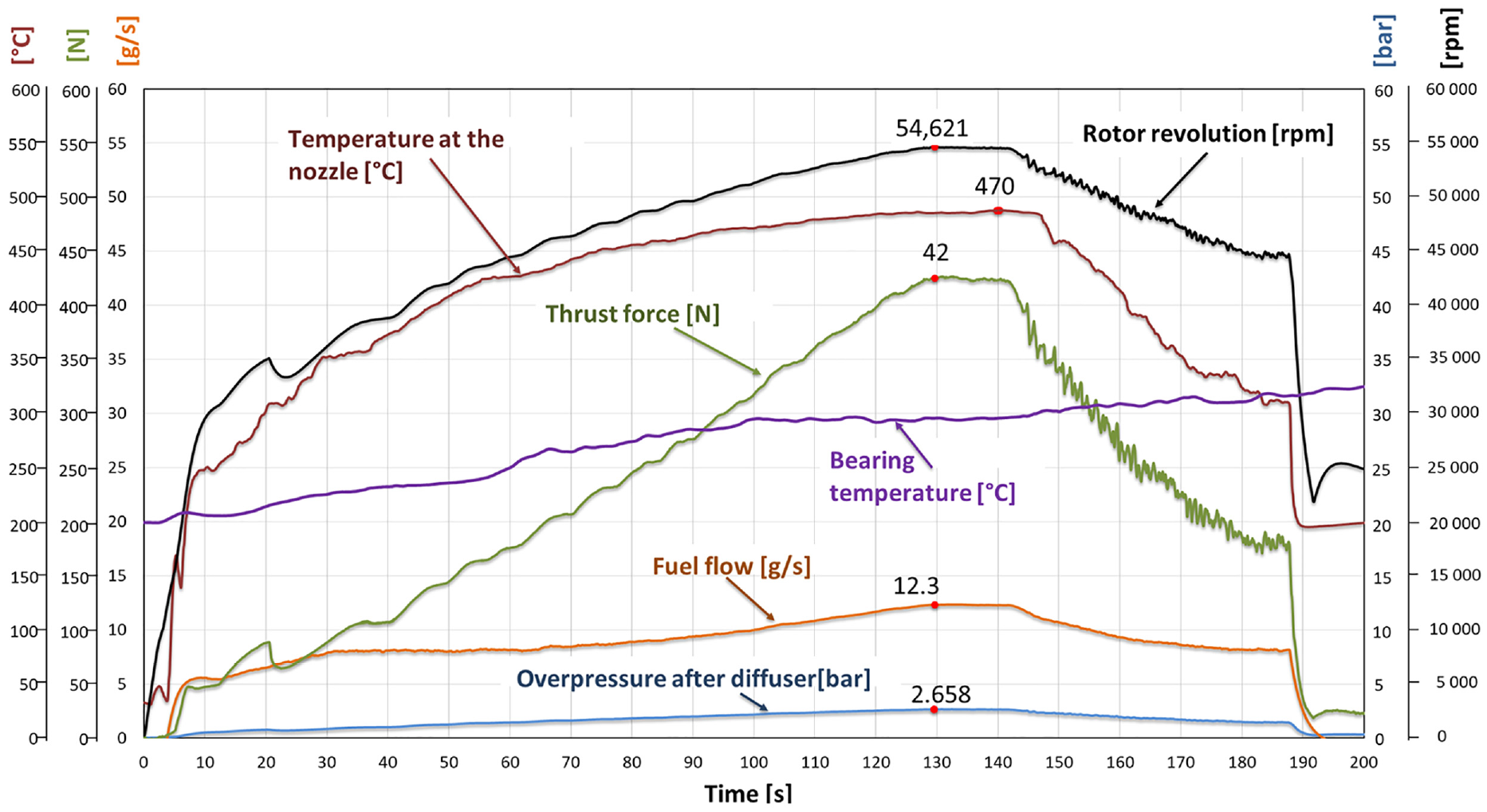
Measured values from acquisition system.
Testing in exploitation
The gas generator was initially developed for the helicopter application. With free turbine section it creates the turboshaft engine which drives the Hornet conventional kind of helicopter, Figure 19 (left). By adding the additional gearbox, this engine, turboprop, is used to drive the propeller for unmanned drone application, Figure 19 (right). The gas generator was also used for propulsion of the special tip-jet type of helicopter, 28 where the generator is placed above the rotor and blades, Figure 19 (middle). During the exploitation of the gas generator through the developing of helicopter and drone projects it was used along all its operational regimes. These tests are maybe the best proof for quality of the methodology and design solution for the multifunctional bulkhead presented in this paper.

Hornet helicopter (left), tip-jet helicopter (middle), and turboprop application.
Identification of the operating conditions of the multifunctional bulkhead
Operating conditions of the multifunctional bulkhead are defined as extreme in this paper because the structure, produced by conventional materials for high temperatures, should withstand mechanical loads (pressure and preload deformation) at very high temperatures caused by hot operating fluid (combustion products of air-kerosene mixture) with very small deformations (0.1–0.2 mm) required from labyrinths in order to achieve good sealing function. Besides that, stress and deformation state of the structure must not interfere with the ability of the bulkhead to perform four functions, explained in detail in Kolarević et al., 14 for the engine to run. So, from an engineering point of view there are several contradictory demands that should be satisfied and the problem is very complex, but the condition for its solution is at least a rough knowledge of bulkhead operating conditions which is the main task in this paper.
The presented methodology is used in order to identify the operating condition of the multifunctional bulkhead for small turbo-shaft engines of back-to-back concept. The main problem is that it is impossible to install any measuring device in the narrow space around the bulkhead structure in order to measure temperature and pressure distribution, main loads of the structure, or to determine the flow parameters. The idea is to use measuring devices at some points to verify the global stream of operating fluid, through the entire engine, and to lay down to the numerical calculation and predictions to simulate the flow around and inside the bulkhead in order to define its operating conditions. Besides the presented methodology some conclusions can be made in combination with Failure Based Design methodology and previous unsuccessful design solutions as mentioned in Kolarević et al. 14
The main conclusion is that pressure distribution is not uniform and it cannot be predicted as a linear drop from higher, at the compressor side opening, to lower value, at turbine side opening, around the bulkhead, as it was done in some previous unsuccessful solutions. 14 Depending on the proximity of the impellers to the bulkhead structure there is more or less a Tesla turbine effect on the pressure distribution. This phenomenon significantly changes pressure distribution and in some cases can create lower pressure value than the boundary pressure values, static pressure at compressor and turbine gaps. This results in change of stress and deformation of the bulkhead structure or even in change of deformation directions, toward the turbine or toward the compressor. In future work, it is planned to identify the pressure distribution on other regimes and other types, with regards to engine dimensions, of back-to-back turbo-shaft engines in order to present some universal equation that can predict closely enough the pressure distribution depending on the diameter of the bulkhead and proximity to the impeller. For the multifunctional bulkhead, which is the case study in this paper, pressure distribution is shown in Figure 6. We notice for now that for gaps larger than 1 mm pressure distribution can be approximated as constant, as on the turbine side. Pressure inside the bulkhead is more or less uniform because of the large volume in which the flow of relatively cold air for cooling the turbine is low.
Temperature distribution along the structure of the bulkhead is highly nonuniform. There is a temperature rise on the outside diameter area of the elastic and support plates due to reliance on hot turbine stator surface. On the other side of toward lower diameters there is a sudden drop of temperature due to introducing the relatively cold cooling pressured air through small holes in its structure. There is also a rise in temperature in the proximity of the axial and radial labyrinths due to sealing function as a negative effect. The Tesla turbine effect also raises the temperature with diameter slightly on the compressor side. The body temperature of the bulkhead is shown in Figure 9. It can be concluded that there is an increase in temperature on the compressor side of the bulkhead with increase in diameter, and there is a sudden increase in the temperature of the bulkhead with diameter on the turbine side. The only way to compensate the temperature is to permit the bulkhead outside deformation with the use of temperature consistent material.
Pressure and body temperature distribution are the main two loads, beside preload of the elastic plate which can be altered depending on the function, of the structure and from previous Figures 6 and 9 it can be concluded that the presented operating conditions are locally nonuniform. These results are shown to be enough for designing a satisfying solution retaining the idea to divide the assembly into a supporting cold part of the structure that withstands mechanical loads and a deforming hot part of the structure that withstands mostly thermal loads.
Discussion and results
The results obtained with the numerical CFD simulation and the measured values with the acquisition system are matching within acceptable limit, under 5% of error. Based on this, it can be validated that the simulation is truthful enough and some conclusions can be made. CFD simulations show that there is a significant reduction in static pressure in the cavity between the compressor and the multifunctional bulkhead additionally fortified by the Tesla turbine effect. This reduction has a consequence on lowering the resulting axial force on the engine rotor assembly which directly increases service life of the bearing arrangement. The simulation also shows that there is cold air flow for cooling through the system of holes on the supporting and elastic plates of the multifunctional bulkhead assembly. From the solution of the CFD numerical simulation, one could see that there is a large amount of heat that comes from the stream in the cavity on the turbine side and it affects mostly the elastic plate of the bulkhead assembly, as design predicted. Thus, it can be said that the heat shield function is achieved. It can also be seen that there is a small increase in temperature of flow in the cavity space toward the compressor due to axial labyrinth presence, which is an undesirable effect.
The results from the numerical thermal calculation show that the elastic plate mostly operates at temperatures of 700–800 K and the local highest stress of 300 N/mm2, which is acceptable, as it is made from highly resistant Inconel 718 alloy. On the other side, the supporting plate operates at a much lower temperature of 600 K, but it is more massive in dimension in order to contribute to the rigidity of the assembly and it is made from heat resistant stainless steel X17CrNi16-2 (1.4057). Stress and deformation analysis, which includes thermal and pressure loads, results in maximum stress around 150 N/mm2 on the supporting plate, which gives a safety factor of 2.6. Maximum stress of 300 N/mm2 on the elastic plate gives a safety factor of 3.2 for its temperature state. The deformations are within the permissible limits governed by labyrinth clearance. The S-shaped elastic plate cross section provides the uniform air gap of around 5 mm between the turbine and elastic plate which is big enough to prevent the influence of the Tesla turbine effect in this area. The deformation of the multifunctional bulkhead in the numerical simulation shows that it satisfies the rigidity demands.
After experimental testing on 54,621 rpm, the engine was disassembled and every part of the subassembly was analyzed visually and by measuring relevant geometry. It was noted that every part of the subassembly maintained its original properties. Figure 20 shows multifunctional bulkhead assembly photos after the test.

Multifunctional bulkhead assembly after test (side toward turbine on left and side toward compressor on right). 14
As the integrity of the structure together with both labyrinths was preserved, it can be concluded that the stress-deformation state of the multifunctional bulkhead assembly was as predicted and simulated. This concept of the design, where the structure is separated on mechanically loaded parts and thermally loaded parts, was confirmed for extreme thermo-mechanically loaded structures, such as the bulkhead assembly. Later exploitation tests done on higher operating regimes further strengthen the presented design solution and confirm its quality together with methodology.
There is a change in color on the small ring area on the turbine disk back and that confirms that it was subjected to the flow of the cooling air, Figure 21. At further tests we managed to measure the axial force on the bearing arrangement in order to confirm the amount of reduction of the resultant axial force. Unfortunately, it was not reduced to satisfactory level, so some improvement still need to be done on this issue.

Back side of turbine disk.
In order to additionally decrease the axial force on gas generator rotor, a following design solution, shown in Figure 22, is proposed. The idea is to improve the axial labyrinth effect but on the other principle, that is, the entire surface of the multifunctional bulkhead is brought closer to the compressor disk in order to maximize the Tesla turbine effect. Previous axial and radial labyrinths are practically made as one part, shown with yellow color.

Proposed new design solution for the multifunctional bulkhead.
Conclusion
The main contributions of this article are:
identification and analysis of the operating conditions of the multifunctional bulkhead, a part that splits the cold and hot section of gas generators of back-to-back rotor concept which operates in a very narrow space and withstands extremely high mechanical, fluid, and thermal loads;
the innovative conceptual design solution, that implies the division of the bulkhead into two parts, the support part to withstand mechanical loads and the elastic part to withstand thermal loads in order to avoid complex thermo-mechanical load of structure, that can be used for similar gas generator concept with small dimensional harmonization;
the analysis of the state of the multifunctional bulkhead for application in specific kinds of gas generators.
The partial contributions of the work are the following.
Flow parameters in the space between the radial compressor and turbine’s back, with installed bulkhead to separate them, are identified. These parameters show that Tesla turbine effects govern the pressure and velocity distribution in this narrow zone, due to proximity of the stationary parts and the parts rotating at extremely high speeds. This fact can be used for more effective sealing as proposed in new design solution in the Figure 22.
Numerical analysis provides the information of the temperature, pressure, stress and deformation state of the multifunctional bulkhead assembly. In this case study, the elastic plate endures very high temperatures of around 800 K, while withstanding stresses of around 300 N/mm2. The result shows that safety factors are high enough while deformations are on a satisfactory level so the bulkhead could perform the demanded functions. In terms of stiffness demands support plate showed satisfying behavior.
Experiments in laboratory and in exploitation are the proof of numerical calculations and the guaranty of a successful design solution of the multifunctional bulkhead for operation in conditions of extreme mechanical, fluid and thermal loads.
In future activities some topology optimization 29 should be performed in order to minimize the mass of the multifunctional bulkhead subassembly by more evenly distribution of stresses along the structure or even to increase stress level. Topology optimization could be also used to additionally decrease deformations in order to increase the efficiency of the labyrinths.
A new design solution for multifunctional bulkhead, based on the information gathered from the results of the presented numerical and experimental investigation, is proposed, Figure 22, in order to lower the resultant axial force on the gas generator rotor so as to increase the bearing life and service overhaul.
Footnotes
Handling Editor: Chenhui Liang
Declaration of conflicting interests
The author(s) declared no potential conflicts of interest with respect to the research, authorship, and/or publication of this article.
Funding
The author(s) disclosed receipt of the following financial support for the research, authorship, and/or publication of this article: The presented paper is a result of the research supported by MPNTR RP according to the contract 451-03-9/2021-14/200105 since 5th February 2021.