
Abstract

Planetary gear set contains many kinds of nonlinear factors, such as time-varying meshing stiffness, bearing support, backlash, and comprehensive transmission error, which will deeply affect the gearbox response behaviors and vibration characteristics. During the operation of planetary gear set, there are several gear pairs meshing simultaneously, which will lead to multiple vibration sources and complicate vibration transmission. The revolution of the planet gears makes the meshing force of the gear pairs vary periodically, and the continuous motion of the meshing point also changes the length of vibration transmission path. This study aims to establish a hybrid model that can simulate the vibration signals of gearbox measuring points through fusing the dynamic model of planetary gear set and the transmission path model. Through the simulation analysis, the vibration characteristics of the measuring point signal of the planetary gearbox are revealed, and the crack fault of the planet gear tooth is effectively isolated. Finally, the availability and validity of the presented model are experimentally verified, and the magnitude match is up to 78%. The model can not only provide a theoretical basis for data-driven fault diagnosis methods, but also solve the pain point of diagnostic samples scale and balance by simulation means.
Introduction
Compared with fixed-shaft gear transmission, planetary gear set is widely applied in various fields of modern industry because of its many unique merits. Planetary gear set can accomplish large transmission ratio output in a limited narrow space, and achieve the function of transmitting high power and speed with small volume, light weight, smooth transmission, and high efficiency. Therefore, planetary gear set is used in machine tools, electric power, construction cranes, metallurgy industry, especially in the transmission system of dual-use vehicles, ships, helicopters because of its remarkable power dividing characteristics.
In actual scenarios, the planetary gear set usually works under severe conditions of dynamic heavy load and variable operating conditions. In addition, the structure of planetary gear set is complex, including a large number of vital components such as sun gear, planet gear, ring gear, shafts, and bearings, etc., so the failure rate of planetary gear set remains high. As the critical part of power drive and transmission, once the planetary gearbox fails and cannot be eliminated in time, it will cause economic loss in terms of downtime and mission failure, or serious safety accidents. Therefore, the prognostics and health management (PHM) for planetary gearbox is very urgent and has important practical significance.
So far, there are two main fault diagnosis methods for gear transmission 1 : data-driven method and physics-based method. The data-driven method purely relies on the analysis of the previous data from gearbox health status to implement diagnosis or prediction. Data-driven method has attracted the attention of scholars and developed rapidly with the rise of artificial intelligence in recent years. Physics-based method is divided into dynamic modeling and signal modeling. 2 Based on the in-depth analysis of the structural information and physical characteristics of the gear system, dynamic modeling uses the classical mechanical theory to analyze the dynamic characteristics and internal generation mechanism of the system. The gear system modeling based on dynamics can deepen the understanding of gear damage mechanism and reveal the impact of typical damage modes on the dynamic characteristics of the system in essence. It is of great significance for the fault feature extraction, degradation state identification and remaining useful life prediction of gear box. In addition, the dynamic modeling research can provide simulation data support for the subsequent development of fault diagnosis and prediction algorithms, such as providing a large number of training samples for various artificial intelligence algorithms to solve the problem of samples sparse and unbalance commonly faced by fault diagnosis. Therefore, it is necessary to establish a dynamic model which can reflect the fault and vibration mechanism of planetary gearbox system as much as possible.
In the past decades, some research achievements have been made by domestic and foreign researchers on the physical modeling of planetary gearbox system. Kahraman 3 developed a nonlinear dynamic model of planetary gear set including manufacturing error, assembly error, planet gear spacing arrangement, tooth separations, and time-varying stiffness to study the influence of vital parameters on dynamic load sharing factor. Lin and Parker4,5 set up a classical translational-torsional model of planetary gear set based on the follow-up coordinate system, the natural modes and parametric instability for contact ratios and mesh phasing of gear pairs were also investigated. Parker et al. 6 established the semi-analytical formulation of the helicopter planetary transmission by using the finite element method, studied the dynamic response of the system under variable working conditions, and derived a detailed calculation process of the meshing phase relationships of the planetary gear set. 7 Yuksel and Kahraman 8 quantified the effect of tooth surface wear on the dynamic meshing force impact, and studied its influence mechanism on the nonlinear characteristics of the system. Chaari et al.9–11 considered the influence of the gyroscopic effect and established the energetic Lagrange formulation of the planetary gear set, focusing on the effects of eccentricity, profile and tooth faults (crack and pitting) on the gear ratio and dynamic characteristics of the system. The lumped-parameter model and the FEM of the planetary gear train were set up by Ambarisha and Parker 12 respectively, and the qualitative and quantitative comparison of simulation results were made, and the law of the gear meshing phase under different bifurcation behaviors was also studied. Cheng et al.13,14 developed a pure torsional dynamics model for a helicopter planetary gear set, and quantitatively analyzed and evaluated the gear damage level by using statistical index and gray relational analysis algorithm. Sondkar and Kahraman 15 proposed a three-dimensional dynamic model of a double helical planetary gear set, and emphatically demonstrated the influence of key design parameters such as right-to-left stagger angle, support conditions on the dynamic response. Yi 16 proposed the nonlinear dynamic model of wind power gearbox drive train, and evaluated the effect of average error, amplitude error and other factors on gear load sharing characteristics. Fan et al. 17 established the mapping relationship between the length and position of the carrier crack and the torsional vibration response of the planetary gear set by using the FEM. Hammami et al. 18 built a lumped-parameter torsional model of the gearbox with power cycle, simulated the response characteristics of the system under static load and variable load. Zhang et al. 19 put forward a translational-torsional dynamic model of a two-stage planetary gear set, and studied the influence of system parameters on the natural mode by comparing with the FEM. Wei et al. 20 integrated the lumped-parameter and finite element method, constructed the dynamic model of multistage planetary gear set based on the element equivalence principle for shaft segment, ring gear and carrier, and studied its quasi-static and dynamic characteristics to guide the reliability design and noise control of the gear system. Liu et al. 21 obtained the time-varying meshing stiffness of the gear cracked state using the FEM, and substituted it as a key parameter into the lumped-parameter model to simulate early crack response. Tatar et al. 22 established a six degrees of freedom lumped-parameter dynamic model of a planetary gearbox, and used modal energy analysis to quantify the coupling level of the rotor system. The results show that the gyroscopic effect has a significant influence on the gearbox dominant mode. Mbarek et al. 23 discussed the influence of variable load and time-varying stiffness on the modal strain and energy distribution of planetary gear set through the hammer test. Sun et al. 24 proposed a signal model of planetary gear set considering the transfer path, and studied the effectiveness and advancement of cyclostationary analysis for fault diagnosis under non-stationary rotational speed excitation. Chung et al. 25 optimized the load sharing characteristics of the gear system using only floating members by simulating the dynamic model of the planetary gearbox in the off-road vehicle, so as to reduce the weight and miniaturize the transmission system. Zhang et al. 26 declared the tidal periods phenomenon of the fault meshing position of the sun gear inside the planetary gearbox, revealing the new formation mechanism of the fault vibration response and defining the minimum sample length required for such diagnosis. Han et al. 27 coupled the torsional model of planetary gear set with the MEC model of induction motor, and realized the fault isolation of gear system by identifying the fault characteristics of stator current spectra.
It can be seen from the above literature that dynamic modeling is conducive to in-depth understanding of the natural vibration characteristics and typical fault characteristics, and it is necessary to establish a nonlinear dynamic model that could approximate the real gear system as much as possible, including time-varying stiffness, backlash, transmission error, support stiffness, etc. In addition, the signal model of gearbox measuring point should be developed for verification by real industrial test. Therefore, it is necessary to further investigate the vibration transfer effects between the planetary gear components and the measuring point of the housing. Inalpolat 27 proposed a mathematical model to simulate the vibration transfer effect from the meshing forces of planet-ring pairs to the measuring point by using a weighted Hanning function. Later, the influence factors of the meshing forces from the planet-sun pairs were added to improve the transfer effect model. 28 Feng 29 drew on the above achievements and combined them with the planetary gear set signal model to develop a gearbox measuring point model for exploiting the generation mechanism of fault modulation sideband. Liang et al.30,31 proposed Hamming and Modified Hamming successively to simulate the vibration transfer path, so as to solve the zero-setting defect of Hanning function when the planet gear rotates furthest away from the sensor. Zghal 32 proclaimed a new lumped parameter model by using an energetic approach based on Lagrange formulation, in which the planet gear displacements were implicitly expressed in sensor positions to simulate vibration propagation effects. With the efforts of many researchers, some achievements have been made in the field of transfer path modeling, but there are still some defects that are tough to be overcome. Firstly, when Hanning function is used to represent the periodic modulation generated by the rotation of the planet gear, the end point will be set zero, and its continuous action range is only the minor arc close to the sensor. With the increase of the number of planet gears, this assumption will lead to the risk of error accumulation and even failure of crack tooth meshing simulation. Secondly, whether Hanning or Hamming function is applied as the weighting coefficient of vibration response, its essence is only an empirical expression to approximate the periodic variation of transmission path, and there is no accurate mathematical expression of transmission path for the specific gearbox physical object. Therefore, it is necessary to develop a simulation model that is as close to a realistic physical system as possible, reflecting essentially the typical damage mechanism of a planetary gearbox.
At present, a lot of efforts have been made in the dynamic modeling of planetary gear train, but the comprehensive model containing several nonlinear factors is rarely employed in the simulation. In addition, the accuracy and effectiveness of transmission path modeling for gearbox needs to be improved. In this paper, a translational-torsional model of the fault planetary gear set is established on the basis of classical mechanics theory, which contains several nonlinear factors such as time-varying meshing stiffness, variable bearing support, backlash, and comprehensive transmission error, and the dynamic meshing forces between gear pairs in the system are fully obtained. Then, the FEM is used to analyze the frequency response of the housing to acquire the exact mathematical expression of the vibration transmission effect from the meshing excitation to the sensor measuring point. The resultant vibration signal of the measuring point on the planetary gearbox is obtained by the joint simulation of the two models. Finally, the effectiveness and correctness of the hybrid model for vibration response simulation of fault gearbox are verified by bench test. The proposed planetary gearbox model can effectively deepen the understanding of system fault mechanism and response characteristics, provide simulation big data support for the advanced artificial intelligence algorithms in gearbox fault diagnosis to solve the pain point of samples scarcity and imbalance.
Dynamics modeling and simulation analysis of faulty planetary gear train
In this section, a translational-torsional model of the faulty planetary gear set using lumped parameter method is established, which has the following characteristics compared with the previous studies: (1) several nonlinear factors are incorporated to the model, including time-varying meshing stiffness, bearing support stiffness, system damping, gyroscopic, and centripetal forces, comprehensive transmission error and backlash; (2) some key dynamic parameters are evaluated using more accurate models, such as meshing stiffness calculated by the mainstream potential energy method, bearing support stiffness estimated by the time-varying model. The inclusion of these large number of nonlinear factors allows the presented model to simulate the gearbox physical system at a more refined level, and obtain the three-direction vibration response signals of all components in the system.
Dynamic equations
The planetary gear set usually consists of key components such as the sun gear (s), planet gear (p), ring gear (r), carrier (c), and support bearings, etc. While the planetary gear rotates, it also revolves around the sun gear with the carrier. The translational-torsional model takes into account the vibration of each key component in two translational directions and one torsional direction, whose mechanical sketch is shown in Figure 1. The coordinates

Translational-torsional model of the planetary gear set.
Based on the above mechanical model, the relative displacement between the sun-planet pair can be expressed by the following formula:

Similarly, the relative displacement of the ring-planet pair is as follows:

where
The relative displacement of carrier-planet pair is as follows:

Therefore, the dynamic equations under the follow-up coordinate system of all components can be established by using Newton’s second law separately as follows:
For the carrier:

For the ring gear:

For the sun gear:

For the planet gears:

where

Considering the tooth profile error in the real gearbox system due to the manufacturing and processing of gear teeth,

where
Substitute equation (9) into equations (4)–(7) and write it in matrix form as follows:

where the symbols meaning in the above equations can be found in Appendix.
In order to form a lubricating oil film within the meshing tooth profiles, appropriate backlash must be left to avoid gear meshing transmission jamming caused by tooth friction heat expansion. The backlash formula can be given by the following equation (11),34,35

where b is half of the backlash constant.
Newmark-β is a method that generalizes the linear acceleration and is widely used to solve dynamics differential equations of mechanical system because of unconditional convergence under set parameters and efficient solution. It is necessary to integrate the backlash formula with the dynamic equations into matrix form for using this efficient numerical simulation method.
Take the sun-planet1 as an example, the dynamic transmission error of the gear pair considering backlash along the action line can be expressed as 36 :

where

Thus, the dynamic meshing force within sun-planet1 pair can be calculated as follows:

where

Substituting equations (12)–(15) into equations (4)–(7), a 21 degree-of-freedom planetary gear set dynamics matrix equations considering time-varying meshing stiffness, bearing support, comprehensive transmission error, the effect of gear backlash have been constructed.
Time-varying meshing stiffness evaluation of planetary gear train
Time-varying meshing stiffness is a key parameter in the study of the vibration characteristics of gear systems. At present, there are many kinds of evaluation algorithms for mesh stiffness, such as finite element method, RMAX software method, potential energy method, etc. In addition, ISO6336-1-2006 also provides some reference for mesh stiffness calculation. Mohammed 37 studied the mesh stiffness calculation method under large crack size. Chen and Shao38–40 conducted an intensive study on the meshing stiffness of fixed-axle gear set and planetary gear set, and combined the finite element model with potential energy method to establish the non-penetrating crack stiffness models at different levels. Wan 41 proposed an accurate analytical model to calculate time-varying stiffness which takes into account the fillet-foundation deflections and the flexibility between root circle and the base circle. Ma 42 considered the transition curve between the tooth root circle and the base circle, and concluded that parabolic curves for crack path and limiting line were optimal by comparing the calculation results of different line types. Then it is improved the disadvantage of repeatedly considering the fillet-foundation deformation in the stiffness model. 43 Liang 33 proposed the analytical model of external mesh stiffness using a modified cantilever beam, and investigated the phase relationship of each meshing pair of the planetary gear set. Then, a mapping model of mesh stiffness with severe pitting was developed. 44 In general, the potential energy method is still the mainstream to evaluate the meshing stiffness. Reference to our previous research fruit,45,46 the improved potential energy method is applied in this paper.
The improved potential energy method is to equivalent the gear tooth into a cantilever beam, and calculate the Hertz energy

where the subscripts 1 and 2 represent gear and pinion, respectively.


where the meanings and calculation methods of above formulas can be referred to Shen et al. and Mohammed et al.47,48
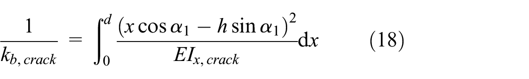
As shown in Figure 2, the gear tooth containing non-uniform crack can be cut into a finite number of slices, and the crack depth of each slice is considered as a constant. The bending stiffness and shear stiffness of the gear teeth are calculated with reference to the uniform crack. The overall bending stiffness and shear stiffness are obtained by numerically integrating the tooth width, as shown in equations (22) and (23).


Schematic diagram of stiffness calculation with non-uniform crack. 46
Therefore, equation (16) is transformed as:
Since the modeling of gear meshing stiffness is not the focus, only the case of uniform crack is investigated for simplicity. The structural parameters of a single-stage planetary gear set in a main reducer are shown in Table 1. The meshing stiffness of planet-ring pair with different crack levels when
Structural parameters of a planetary gear set.

Mesh stiffness of different crack levels on a planet gear tooth.
In fact, there are simultaneous meshing actions of eight gear pairs during the operation of the planetary gear set. When the sun gear meshes with all four planet gears, there may be phase difference between their meshing forces. Similarly, there may be phase difference between the four ring-planet pairs. In addition, each planet gear is engaged with both the sun gear and ring gear, and the phase relationship between the two meshing forces is also of concern.
Parker and Lin 7 conducted in-depth research on the meshing phase relationship of planetary gear set, and found that it is mainly related to the position angle of the planet gear and the number of gear tooth.
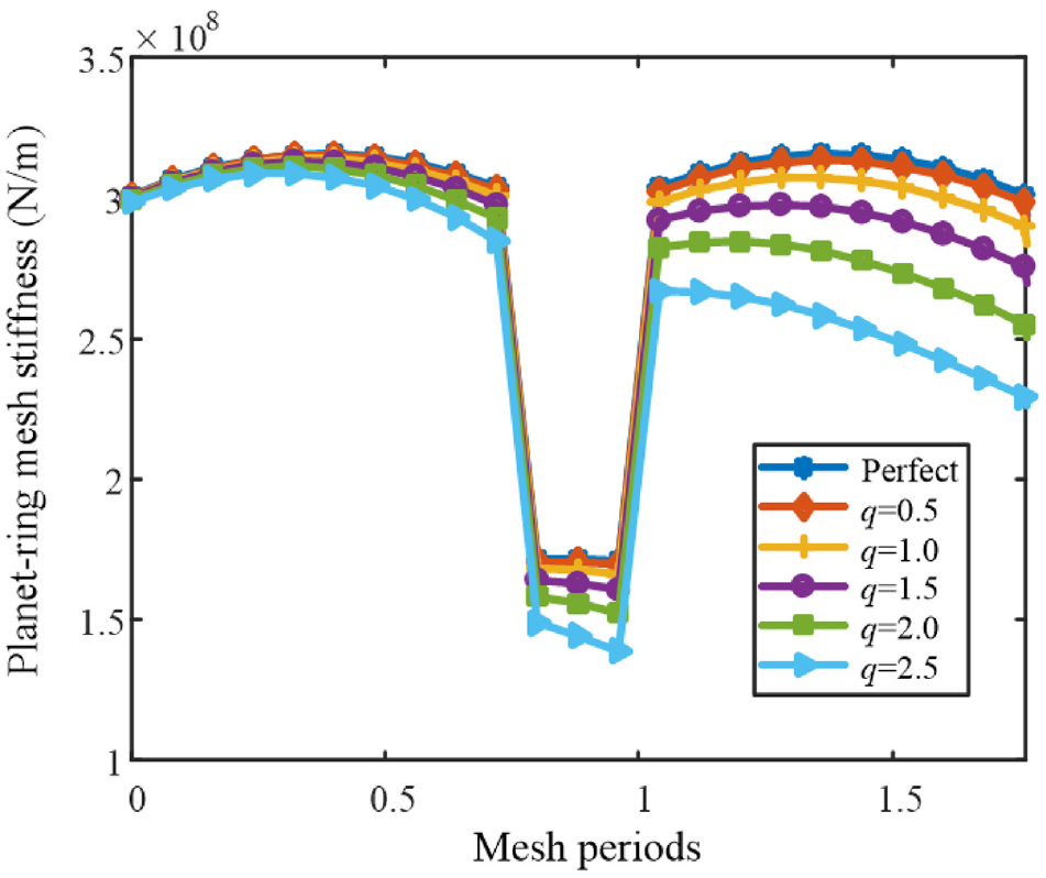
Without loss of generality, it is assumed that there is a crack q = 1.5 mm at tooth root (ring gear side) of planet gear p1. According to the structural parameters listed in Table 1, the amplitude and phase results of eight groups meshing stiffness of the planetary gear set are shown in Figure 4 and Table 2 referring to.
7

Meshing stiffness curves of planetary gear set with a planet gear crack: (a)
Relative phases of the planetary gear set.
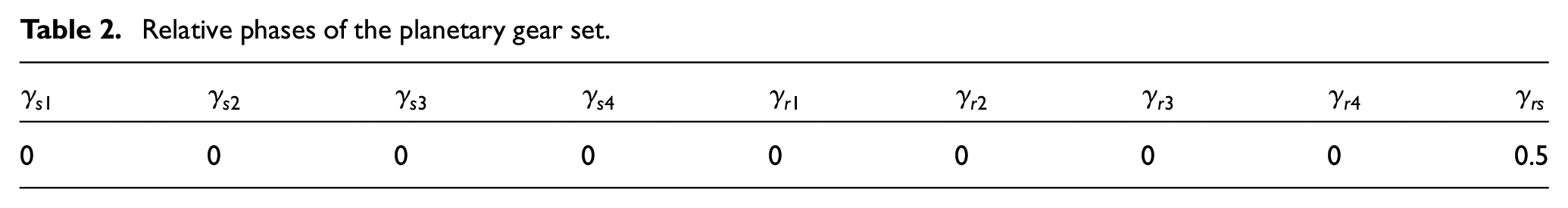
It can be seen from Figure 4(a) that the meshing stiffness amplitudes of four groups of sun-planet pairs keep the same and the phases remain synchronous as the perfect condition because the crack on the ring gear side is deemed that the sun-planet pairs are perfect. Figure 4(b) shows a significant amplitude decrease due to the presence of tooth crack, as shown by the yellow circle, which is distinguishing from the meshing stiffness of other three planet-ring pairs in Figure 4(c). In addition, the four phases of the planet-ring meshing forces remain the same. The
Bearing stiffness evaluation
As a precision mechanical part, rolling bearing has the remarkable advantages of low friction coefficient and power transmission efficiency. It is widely applied in various fields such as construction machinery and national defense equipment. As an important supporting component of rotating machinery, rolling bearing facilitates the smooth rotation at high speed, reduction friction, and bearing heavy load. It plays an important role in mechanical operation and determines the performance and reliability of mechanical equipment. Rolling bearings are widely used in the planetary gear set of gearbox because of the several components with complex motion relationships. In the planetary gear set listed in Table 1, the planet bearing is HK3020, whose parameters are shown in Table 3 below:
Parameters of planetary gear bearing.

As an important part of the gearbox, the mechanical properties of the bearing will also affect the dynamic behavior and vibration response characteristics of the system. From the dynamic model of planetary gear set established in the previous section, bearing stiffness is one of the most critical dynamic parameter. Therefore, it is necessary to evaluate the bearing stiffness.
It is assumed that the bearing only bears radial load

Variation of the rollers in spatial position: (a) even pressure and (b) odd pressure.
Without loss of generality, the bearing stiffness under odd pressure state can be evaluated and the bearing radial deformation is obtained by the following empirical formula 49 :

where

Substituting equation (26) into equation (25), the bearing stiffness under odd pressure is obtained:
The bearing stiffness under even pressure can also be calculated by the above formula. It should be noted that the maximum nominal load on the roller is the decomposition force on both sides of the action line in this case.
Assuming that the bearing stiffness is isotropic,


where
Numerical simulation and analysis
In this section, the dynamic model of faulty planetary gear set will be numerically simulated to investigate the vibration response characteristics at different crack levels. The main physical parameters have been listed in Table 1, and other dynamic parameters are shown in Table 4. It is assumed that the sun gear and carrier as input and output components are subjected to the applied torques
Dynamic parameters of planetary gear set.

Operation parameters of the planetary gear set.

Assumed the crack occurs at planet gear p1, the dynamic transmission errors

Dynamic transmission error
As can be seen in Figure 6(a), the response signal in case 1 is stable, and the basic vibration response comes from the periodic variation of the gear system meshing stiffness. When there is a small-scale crack (case 2) on the planet gear and the fault tooth enters the meshing duration, there are a series of sudden spikes in the time-domain response signal, but the spikes are still very weak at this case, as shown by the red arrows in Figure 6(b). And during the time when the faulty tooth is not involved in the engagement, the response amplitude is basically no different from that in the perfect case. With the extension of the crack length, the peak abrupt changes of the vibration response become more and more obvious, and present vivid periodic characteristics, as shown in Figure 6(c). The spikes period is Tp, which corresponds to the local fault frequency fp of the planet gear in Table 5. The above features are distinct fault symptoms, which imply that there must be a tooth fault on the planet gear p1.
Figure 7 shows the frequency-domain fragments of dynamic transmission error

Spectrum segments of
Figure 8 shows the dynamic transmission errors of the four planet-ring pairs in case 3. According to the comparison of the four subgraphs, the peak mutation of the response signal

Dynamic transmission errors of four planet-ring pairs in case 3: (a)
The dynamic meshing forces of four groups planet-ring pairs in case 3 can be calculated by equation (8), as shown in Figure 9 below:

The dynamic meshing forces of four groups planet-ring pairs in case 3: (a)
The time-domain characteristics of the four sets meshing forces presented in Figure 9 are agreement with the dynamic transmission errors in general. The dynamic meshing force

Spectrum segments of
Transmission path modeling of planetary gearbox
The fault dynamics model established in the previous chapter can simulate the three-direction responses of each component of the planetary gear set. However, in the engineering practice of prognostics and health management (PHM) for gearbox system, the sensor devices are usually arranged on the surface of the gearbox housing to monitor its vibration level to avoid destroying the structural integrity. Therefore, in order to simulate the vibration signal of the sensor measuring point, it is necessary to establish a mathematical model of the transmission path from the components of planetary gear set to the sensing device. In this section, the transmission paths of the measuring point signal are analyzed at first. Considering the periodic direction change and time variability of excitation source induced by components meshing, the frequency response functions from meshing forces of gear pairs to the measuring point are obtained by the finite element method and fitted to a multi-level Fourier series. Thus, the accurate mathematical expression of the transmission path model is acquired.
Transmission path effect analysis of measuring point signal
During the transmission process of the planetary gear set, the planet gears engage with both the sun gear and ring gear. There are three main transmission paths of the planet-ring pair meshing vibration, as shown in Figure 11. In the path 1, the vibration is transmitted directly from the gear meshing pair through the ring gear to the sensor (the transmission path of the superior arc is ignored due to the long length), as shown in the white dashed line. The path 2 is from the meshing pair through the planet gear body, sun gear, the planet gear closest to the sensor position, and then to the sensor in turn, as shown by the black dashed line. The path 3 is more complex and transmitted from the meshing pair through the planet gear body, planet gear bearing, support shaft, the carrier in turn, and then from the carrier to the sensor through the closest planet gear, as shown by the red dashed line. 29

Vibration transmission paths of the planet-ring pair.
Compared with the path 1, the path 2 and path 3 are longer and involve more parts. Considering the effects of backlash and damping, the vibration attenuation is more severe, and the vibration characteristics are seriously submerged. Therefore, the path 1 is mainly discussed for the vibration transmission path of the planet-ring pair.
There are three main vibration transmission paths from the planet-sun pair to the sensor, as shown in Figure 12. In the path 1, the vibration signal is transmitted from the meshing pair through planet gear, the ring gear, and then to the sensor in turn, as shown by the white dashed line. In the path 2, the vibration signal is transmitted from the meshing pair through the sun gear, the sun gear shaft, support bearing of sun gear shaft, the housing, and sensor in turn, as shown by the black dashed line. In the path 3, the vibration signal is transmitted from the meshing pair through the planet gear, the planet bearing and shaft, the carrier, the carrier bearing, the housing, and the sensor in turn, as shown by the red dashed line. The length of the last two transmission paths does not change with the rotation of the carrier.

Vibration transmission paths of planet-sun pair.
Likewise, the characteristics of the vibration signal may change or useful characteristic information may be lost due to the long route of the last two transmission paths, especially through the complex decay process of bearings. Therefore, the transmission path 1 will be considered as a priority.
As shown above, the shortest and most efficient transmission path for both planet-ring pairs and planet-sun pairs ends up being through the engagement of the planet-ring pairs. Therefore, this part will be modeled in detail.
Mathematical modeling of transmission path
For the planetary gear set with the inner ring gear fixed on the housing, the transmission path from the meshing point of the planet-ring pair to the sensor arrangement point changes periodically during the revolution of planet gear. During the process of the engagement point close to the sensor position, the transmission path gradually becomes shorter and the vibration signal perceived by the sensor becomes stronger and stronger; while when the engagement point gradually moves away from the sensor position, the transmission path becomes longer and the vibration signal obtained by the sensor continuously becomes weaker. The Hanning window and Hamming window functions are often used to describe the effects of transfer paths,27–31 but these functions have certain drawbacks. The aforementioned window functions are only a simplified mathematical formulation for the transfer path effect. Firstly, for specific gearbox housing objects, different physical properties such as size, structure, and material will reflect different transfer characteristics, which cannot be accurately described by the aforementioned window function. Secondly, the Hanning window only considers the meshing vibration between the part of the inner ring gear circumference (1/N) near the sensor and the planet gear, and the simulated transmission path error will be great when the number of planet gears is large. 27 If the failure occurs within the neglected meshing arc, the Hanning window function will fail the simulation. Therefore, this paper will apply finite element method to simulate the housing in modal test, and fit an accurate transmission path model of the planetary gearbox vibration response by calculating the frequency response function between the ring gear and the sensor.
Figure 13(a) and (b) show the 3D geometric model and finite element model of a planetary gearbox housing, respectively. The hexahedral element with fast convergence and high precision is adopted as the element type. The element side length is set 10 mm, and the housing material is steel. The force hammer experiment is simulated through the software to calculate the frequency response function of the housing. The arrow in Figure 13(b) shows the force hammer loading point, and the ring gear is marked successively in clockwise direction at equal intervals. In engineering practice, the sensors are usually arranged in the Z-direction perpendicular to the horizontal plane. Therefore, the vertical acceleration signals of the nodes 1–7 are extracted, and the amplitude frequency functions of all response point to the excitation position are calculated as shown in Figure 14 below. As can be seen from the figure, the farther the nodes of the ring gear are from the excitation point, the smaller the amplitudes of frequency response functions. Due to the structural symmetry of the housing, the frequency response functions of nodes on the left half ring gear to the excitation point can be obtained by mirror.
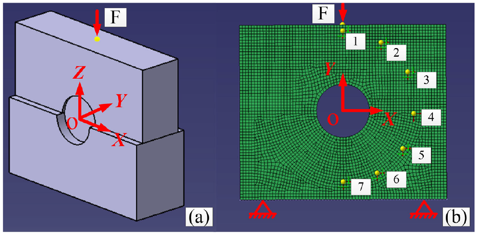
Planetary gearbox model: (a) 3D geometric model and (b) FEM.

Amplitude frequency function of housing.
According to the simulation condition of the dynamic model in the previous chapter, the system meshing frequency fm is 48.17 Hz, as shown in Table 5. The extracted frequency response amplitudes of the ring gear circumference under this case are shown in Table 6 below.
Frequency response amplitude of the nodes 1–7 under meshing frequency.

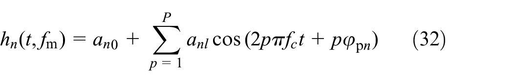
By fitting the frequency response amplitude of each discrete response point with Fourier series, the frequency response function from the ring gear circumference to the excitation position can be obtained as follows equation (31):

where
Considering many kinds of error indicators, the frequency response amplitudes in Table 6 are fitted by fourth-order Fourier series, and the results are shown in Figure 15.

Fourier series fitting curve.
To facilitate the joint simulation with the dynamics model of the planetary gear set, the independent variable
Characteristic analysis of resultant signal
In this section, the dynamic model of planetary gear set and transmission path model are fused for a joint numerical simulation, and finally the virtual measuring point signal of gearbox, namely resultant signal, could be obtained. Through the time domain and frequency domain analysis of resultant signal, the transmission characteristics and dynamic characteristics of the gearbox vibration signal are deepened, and the gear tooth fault mechanism of the planetary gear set is revealed. These analyses are conducive to the development of fault diagnosis algorithms.
The mathematical model of transmission path is established under the global coordinate system OXY, while the dynamic model of planetary gear set is developed based on the follow-up coordinate system Oxy. In order to achieve a joint simulation, the coordinate systems need to be unified. Firstly, the dynamic meshing forces
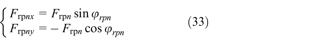
where
According to the transformation relationship between the follow-up coordinate system Oxy and the global coordinate system OXY,
4
the projections of

where
Therefore, the dynamic meshing forces


Figure 16 shows that the four groups dynamic meshing forces of planet-ring pairs in case 1 present obvious amplitude-frequency modulation after two projections, and the phase difference between the adjacent projection forces is
The mathematical model of the resultant acceleration signal at the sensor measuring point is given as follows, and the time-domain simulation results are shown in Figure 18.

Time-domain resultant accelerations: (a) case 1 and (b) case 3.
Observing the time-domain resultant accelerations under two cases in Figure 18, the obvious features are that both signals reflect the high-frequency vibration caused by time-varying meshing stiffness and the low-frequency modulation due to carrier rotation. Comparing the two subgraphs, it can be seen that there are weak periodic impacts on the acceleration signal due to tooth fault in case 3, as shown by the red arrow in Figure 18(b), which requires detailed observation to be known. However, at the time of fault tooth meshing out, the acceleration signals are basically the same in the two cases. Therefore, gear fault diagnosis from the perspective of time domain is not easy, and the signal could be converted to frequency domain for analysis.
Figure 19 shows the frequency domain comparison of acceleration signals under the two conditions. The main frequency components

Frequency-domain resultant accelerations: (a) case 1 and (b) case 3.

Resultant acceleration frequency-domain sections: (a) 75–115 Hz, (b) 75–85 Hz, and (c) 92–102 Hz.
Figure 20 shows the frequency band characteristics around the second order meshing frequency (75–115 Hz). Common ground of both cases is that there are several modulation sidebands with strong energy interval of
From the above time-frequency domain amplitude analysis, it is clear that the time-varying stiffness variation of the perfect bearing has a very limited effect on the resultant acceleration signals. In addition,
Comparison and verification
In this chapter, the resultant simulation signals of presented path model and the classical window function path model are compared in the time domain. Then, the consistency of the resultant signals deduced from the two models with the physical test signals are compared by building a fault diagnosis test platform of transmission system in the laboratory environment. Finally, it is verified that the resultant signal of presented model is accurate and effective to simulate the experimental signals of the faulty planetary gear set through the spectral comparative analysis.
Simulation comparison
To illustrate the advancement of transfer path model proposed in this paper, it is compared with the typical window functions developed in,28–33 as shown in Figure 21. Liang et al. 31 considered that the measured point signal could be regarded as the summation of window weighted vibration of each planet gear because the vibration of planet gears contains both the information of sun-planet mesh and ring-planet mesh, as shown in the equation (36):


Typical window functions for transmission path effect. 32
where
Through the comparative analysis by Liang et al.
32
it was concluded that the resultant vibration signal has relatively good consistency with the experimental signal when the modified Hamming window with
Figure 22 shows the resultant acceleration signals of faulty gearbox measuring points under two different transmission path models. As can be seen from the figure that the amplitude of the simulation acceleration signal weighted by the modified Hamming window is significantly larger than the simulation signal using the presented fitting model.

Comparison of resultant acceleration using two transfer path models.
Experimental verification
To verify the accuracy and effectiveness of the planetary gearbox hybrid model with a tooth fault, a test platform of gear transmission system for fault diagnosis and prediction was built. The platform consists of drive motor, bevel gear pair, two-stage planetary gear set (main reducer), load motor, lubricating oil pump, control system, and data acquisition system, as shown in Figure 23.

Gearbox fault diagnosis and prediction test platform: (a) test rig and (b) data acquisition system.
The rated power of the driving motor is 40 hp, and the speed is adjustable in the range of 0–4000 r/min. The rated power of load motor is 100 hp, and the load torque is adjustable in the range of 0–142 Nm. The control system and data acquisition system of the experimental platform are integrated. The control system is used to set the working mode and bench parameters, while the data acquisition system could collect eight vibration signals, one rotating signal, and one torque signal synchronously, and the sampling frequency range is 2.56–51.2 kHz. The accelerometer is model 608A11 of IMI company, whose sensitivity is 100 mV/g and frequency range is 0.5–10 kHz.
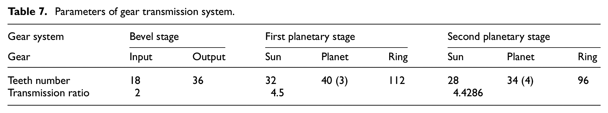
The main body of the test platform is a three-stage gear reducer, which has a total reduction ratio of 39.85:1, and other specific parameters are configured in Table 7.
Parameters of gear transmission system.
The test platform is capable of simulating multiple fault modes and damage evolution processes of key components in the transmission system, providing a validation environment for damage dynamics analysis, degradation state identification and remaining useful life prediction.
To eliminate the influence of environment noise and the original errors caused by installation and manufacturing, all gears are considered perfect before manual fault implantation, while the test under this condition was defined as a benchmark test. Sensors were arranged on the side and perpendicular to the horizontal plane of the main reducer housing, as shown in Figure 24. Spare parts for the second-stage planetary gear set p1 was processed with the wire cutting for root cracks of virous sizes to simulate different crack levels, as shown in Figure 25. The input speed and load torque of the transmission system were controlled and adjusted by the drive motor and the load motor respectively, which could make the test settings of the second-stage planetary gear set consistent with the settings of the simulation conditions.
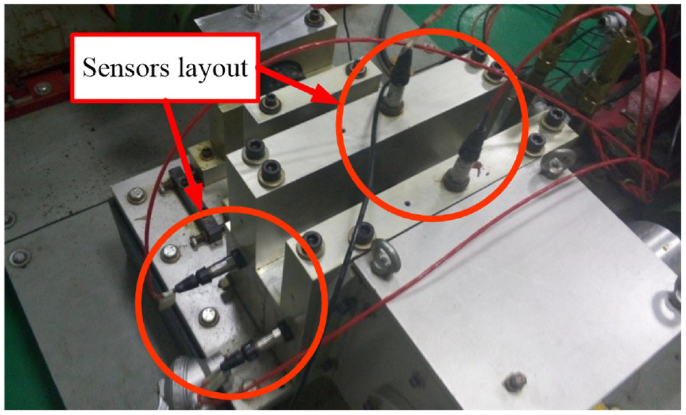
Sensor layout in main reducer.
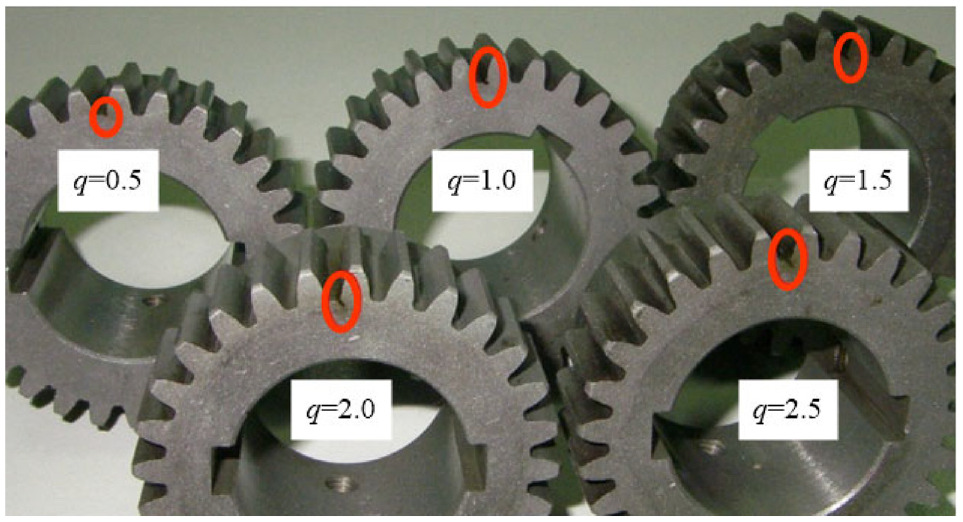
Multiscale crack implanted in planet gear.
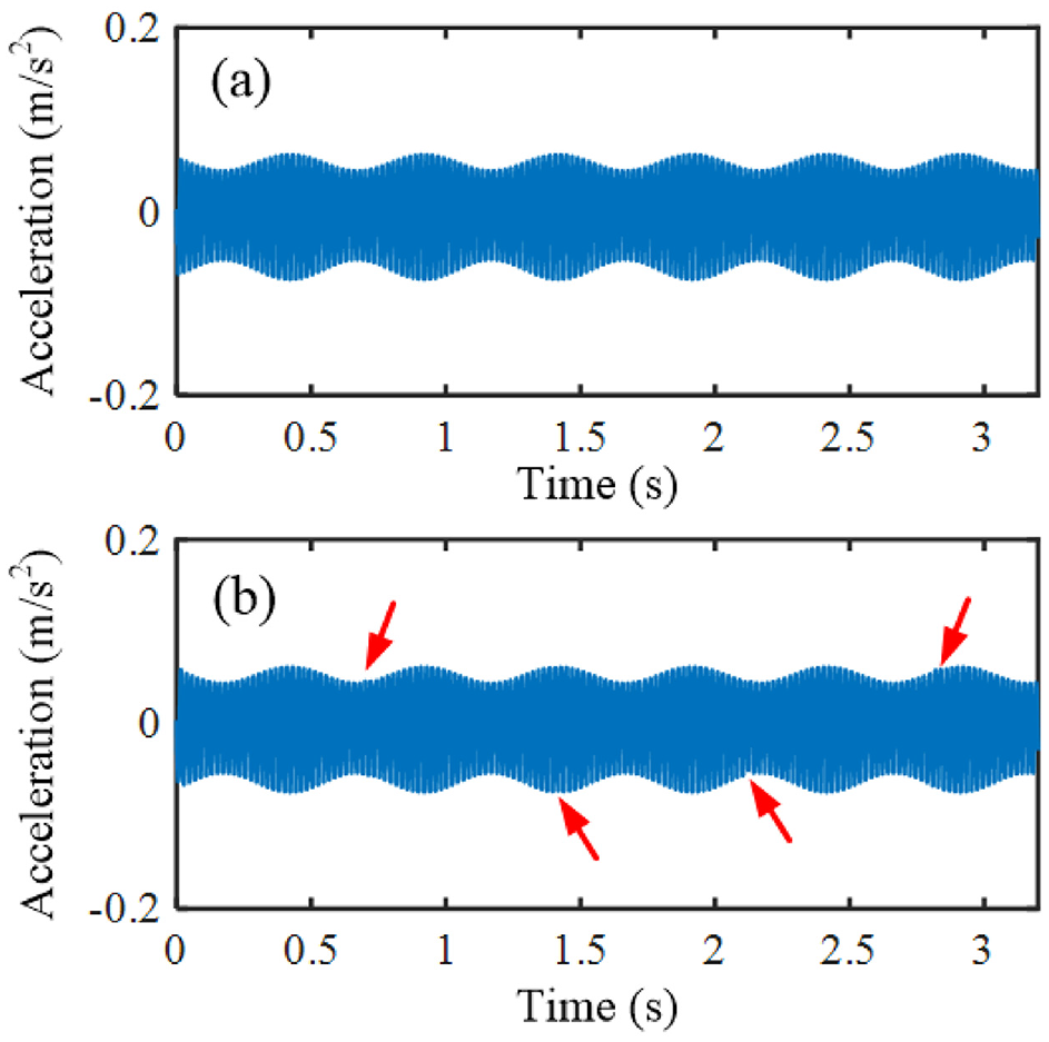
Several sets of experiments were conducted under different operating conditions to analyze the effects of planet gear cracks on the vibration characteristics of gearbox. Figure 26 shows the time-domain vertical acceleration signals of the benchmark test and fault test with q = 2.5 mm.
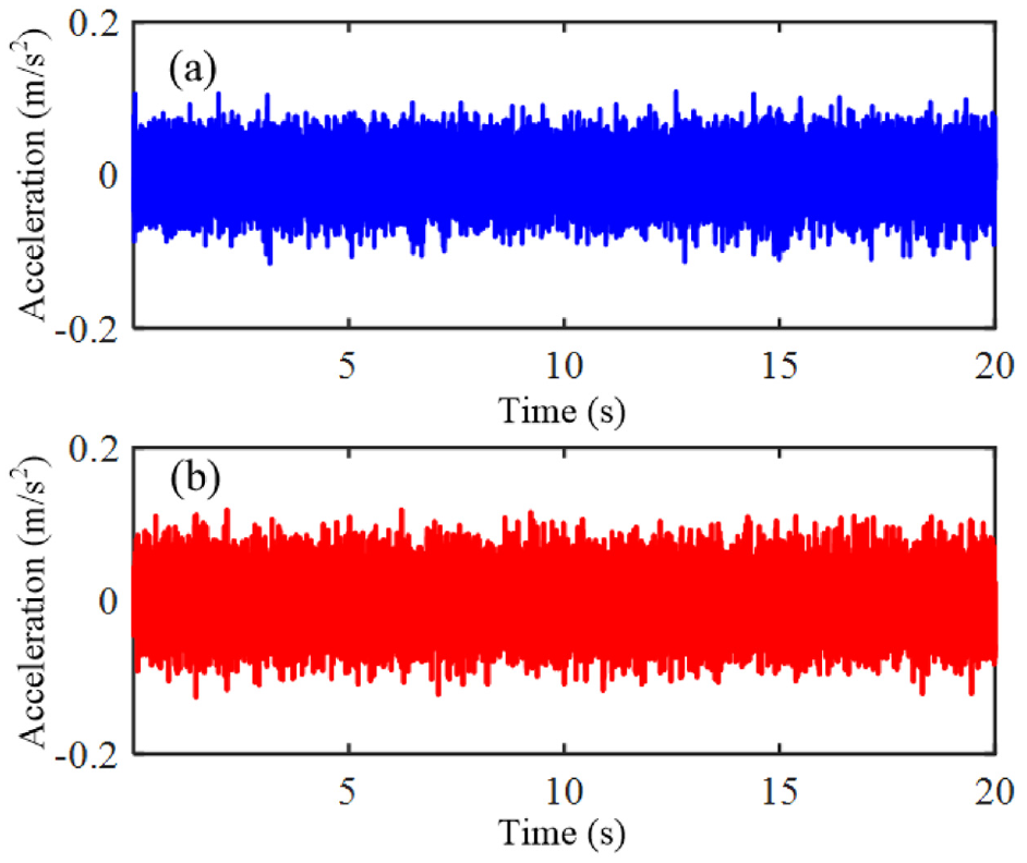
Time-domain experimental signals: (a) benchmark test and (b) fault test.
Visually comparing the simulated signals shown in Figure 22 with the experimental signals shown in Figure 26(b), the overall waveform and amplitude of the resultant signal using the proposed path model relatively match the experimental signal about 78%, while the amplitude of resultant signal weighted the modified Hamming window obviously has a large deviation. This phenomenon occurs because the modified Hamming window is only an extremely simplified empirical representation model class for path effect without rigorous mechanical analysis and the value
Actually, the amplitude of resultant signal using present path model is also smaller than that of the experimental signal evidently, because the resultant signal ignores multiple other minor vibration transmission paths. In addition, the experimental signal will inevitably be mixed with a variety of noises effect, which is also an important factor in the amplitude difference. It is worth noting that there is no significant difference in the time domain curves between the two experimental conditions, except that the overall signal amplitude in the crack condition is slightly larger than the benchmark test. The periodic impact symptoms are not clearly observed, which are overwhelmed by the noise mixed in the measuring process. Therefore, the frequency domain view may be a better perspective to analyze the fault symptoms.
Figure 27 depicts the comparison of the spectrum segments of the test signals in the two cases, covering the frequency band near the first four order meshing frequencies. As can be seen from the figure that the spectral structure and components of the signals in the two cases are basically the identical, and the difference lies in the magnitudes of the frequency components. In the vicinity of the first four order meshing frequencies, except for

Spectrum segments of two conditions: (a) 46–50 Hz, (b) 94–98 Hz, (c) 142.5–146.5 Hz, and (d) 191–195 Hz.
In order to implement a more intuitive comparison, a quantitative analysis of the sidebands (

Comparison of fault modulation sidebands near the first four order meshing frequencies.
As can be seen from the above figure, there is a significant increase in the amplitudes of the sidebands
In addition, the low frequency band of two signals are amplified in detail as shown in Figure 29 below. The response amplitudes are extremely weak for both the benchmark case and crack case, including the fault characteristic frequency

The low-frequency segments: (a) 0–5 Hz and (b) 12–18 Hz.
In summary, the vibration responses of different crack levels are analyzed in the time and frequency domains, and the accuracy and validity of the hybrid model of the sensor measuring point signal on the gearbox are verified. The test signals of the faulty transmission system could be simulated and restored by the proposed model to a large extent.
Conclusion
In this paper, a 21 degree-of-freedom translational-torsional model of the faulty planetary gear set is first developed to simulate the three-direction vibration responses of each component, incorporating several nonlinear factors such as time-varying mesh stiffness and damping, time-varying bearing support, backlash, and comprehensive transmission error. Finite element technology is introduced into virtual frequency response analysis to obtain an accurate transfer path model from the gear components to gearbox sensor measuring point considering the influence of simultaneous multi-point meshing vibration sources, which is different from the existing empirical representation window function. The resultant signal obtained by fusing the two aforementioned models can simulate the gearbox measuring point signal about 78%. In the time domain, the resultant signal has significant modulation phenomenon of carrier rotation frequency, but the fault symptoms and their periodicity are attenuate and not easily detectable; in the frequency domain, a large number of modulation sidebands are present when the planet gear occurs a crack, and the identification and localization of these sidebands can serve better for fault diagnosis. Several benchmark tests and fault implantation tests are conducted to confirm the accuracy and validity of the hybrid model for fault diagnosis. In addition, both simulation and experimental data support the interesting conclusion that the time-varying nature of healthy bearing stiffness has a very limited effect on the response characteristics of the gearbox system. The measuring point model of gearbox established in this paper can not only effectively reveal the fault mechanism and behavior characteristics, but also profoundly reveal the conduction rule of fault response inside the gearbox system, and provide front-end simulation big data support for promoting fault diagnosis and prediction using artificial intelligence algorithms.
Footnotes
Appendix
Handling Editor: Chenhui Liang
Declaration of conflicting interests
The author(s) declared no potential conflicts of interest with respect to the research, authorship, and/or publication of this article.
Funding
The author(s) disclosed receipt of the following financial support for the research, authorship, and/or publication of this article: This work is financial supported by the National Key Research and Development Program of China (Grant No. 2018YFB1702401), the National Natural Science Foundation of China (Grant No. 51975576, 52105133), and the Defense Industrial Technology Development Program (Grant No. WDZC20205500301, WDZC20205250305).