
Abstract
In shipbuilding, welds in sub-assemblies and unit-assemblies are long and various type. The robot arm needs the gantry movement to cooperate with the welding operation. However, there are joint redundancy and double-arm coordination problems, which cause difficulties in the welding trajectory planning. This paper proposes a strategy of decoupling the dual-arm system into a single-arm system for separate planning and prioritizing joint motion, and conducts welding trajectory planning research based on Matlab’s Simscape Multibody. Firstly, the 3D model of the welding workstation is established, its structure, the operation mode of the joint link and the degree of freedom are analyzed. The 17-DOF welding workstation is decoupled into a single-arm 9-DOF system, a kinematic model is established, kinematic analysis is carried out. The Matlab robot toolbox is used for simulation verification. Then the discretization of weld types and poses in sub-assemblies and unit-assemblies workpieces is analyzed. Finally, the welding workstation and workpiece model are imported into Simscape Multibody of Matlab to simulate the trajectory planning of different types of welds. The simulation results prove the effectiveness of the strategy and have certain reference significance for on-site welding in shipbuilding.
Introduction
In the shipbuilding industry, assembly is divided according to the flow direction. In the advanced manufacturing stage, the construction of the hull is divided into three flow stages: sub-assembly, unit-assembly, and grand-assembly. Figure 1 shows the design application of the principle of group separation. Due to the large number of sub-assemblies and unit-assemblies and the extensive and complex flow directions, only sub-assemblies and unit-assemblies are considered in the intelligent welding workstation. Sub-assemblies and unit-assemblies are a production management mode of shipbuilding and are also the production stages of hull segment assembly. It is a production management method developed by the modern shipbuilding industry in order to speed up shipbuilding, improve shipbuilding quality, and form large-scale production. It is to process the simplest hull structural components of ships on a fixed site.1–3 Unit-assemblies are the manufacturing process of an assembly consisting of a batch of parts and components. Sub-assemblies are the manufacturing process in which two or more parts are assembled on a platform to form a component. The typical forms of unit-assemblies include tube floors, double bottom floors, and small floors in topside tanks. Typical forms of sub-assemblies include T-row components, standard components, etc. Welding is an important step in hull assembly and an important factor affecting the quality of the hull.4–6,21 Many stations and processes in the processing of sub-assemblies and unit-assemblies in shipbuilding must rely on welding. Most of the sub-assemblies and unit-assemblies of shipbuilding enterprises still use the traditional manual welding method, which has low welding efficiency, low degree of automation and high labor intensity. Therefore, it is very necessary to carry out trajectory planning simulation research on welding robots.

Different forms of assemblies.
Depending on the type of hull design, the size of the workpiece used for segmented welding in sub-assemblies and unit-assemblies generally has various specifications. The size of the workpiece is large and the height difference is large, which requires the welding equipment to be able to move quickly and flexibly in a wide space. The active radius of industrial welding robots is usually 1.5 m, and this working range is also much larger than the working range of market-standard welding robots. Therefore, on the basis of the traditional standard welding robot, some different forms of auxiliary devices are added, which are mainly divided into the following three categories: gantry type, trolley-track type, and remote control trolley type. On the basis of the traditional manipulator, a gantry is attached to extend the moving distance in all directions and expand the reachable working space at the end of the manipulator, so as to meet the welding operation requirements in the wide space of the equipment.
The welding workstation has 17-DOF, which can perform flexible welding operations for welding seams of various sizes and different positions, but it also introduces new difficulties to the problem of trajectory planning. Even if the dual-arm system is decoupled, it is a single-arm system with 9-DOF, adding 3 degrees of freedom in the three-axis directions of the gantry, resulting in infinite inverse solutions of the redundant degree-of-freedom manipulator. The core of the motion planning of the welding manipulator in Cartesian space is to obtain the corresponding relationship between the pose of the end effector and the rotational position of its joints. For a 6-DOF manipulator, the end pose is usually expressed by mathematical analytical expressions, the motion trajectory is decomposed into discrete points, and the joint positions of these discrete points are solved by inverse kinematics and screened for optimization. When the robot performs welding operations, it needs to coordinate the control of its arms to complete the welding task.7–9 For example, two arms simultaneously weld two welding seams to improve welding efficiency, or two robotic arms perform double-gun fine welding on different sides of the same weld. The welding workpiece is usually placed under the gantry, and there may be a certain distance between the position of the workpiece and the mechanical arm. The type and length of the weld on the workpiece are also different. Therefore, the following issues should also be considered: The welds on the workpiece to be welded have various forms, including straight-line welds and arc-shaped welds, etc. Welding workstations have joint degrees of freedom redundancy and dual-arm coordination problems. The trajectory planning is not linked to the actual workpiece welding.
For the trajectory planning research of welding robots, the commonly used methods include polynomial interpolation, spline interpolation and some intelligent algorithms.10–14 Ning et al. 15 planned the trajectory of the 6-DOF welding robot in joint space and Cartesian space; Wang et al. 16 used the partitioned particle swarm algorithm to plan the welding point path of the 6-DOF welding robot; Amruta Rout et al. 17 proposed an optimal time trajectory planning method for a 6-degree-of-freedom welding robot based on the TLBO algorithm; Liu et al.18,19 proposed an optimal trajectory planning method for a multi-manipulator collaborative welding robot. The motion trajectory is interpolated into each joint space using a cubic b-spline curve, and the motion time node is optimized based on the particle swarm algorithm. Luo et al. 20 established kinematic and dynamic models of the friction stir welding robot. The trajectory equation of the welded joint under the condition of melon flap welding was established, and the spline trajectory was fitted by several discrete points. The trajectory planning and motion parameters of each joint under the condition of melon flap welding were obtained. Offline programing is also commonly used for trajectory planning of marine welding robots. Zych 21 propose a hybrid solution to sensor data to integrate the programing of robots into production processes to optimize individual production processes. Zheng et al. 22 propose a hybrid offline programing method that systematically combines CAD-based, vision-based, and visual-CAD interactive activities to overcome the limitations of existing automatic program generation methods for robotic welding systems. Aiming at the trajectory planning problem of robot and external axis coordination. Yuan et al. 23 propose a mobile collaborative welding method for complex welds. The collaborative welding method includes three steps: weld seam acquisition, weld seam classification and segmentation, and welding task assignment. It proposes a method of obtaining the spatial location features of welds based on human-machine collaboration. According to the spatial location characteristics of the weld, the welding type is identified, classified, and segmented. Finally, assign the welding tasks to robots and AGVs. Wang et al. 24 and Wang 25 reduced the order and linearization of the gantry-type double-arm welding workstation model and used the predictive control algorithm to simulate, with the help of Simulink tools, the welding state of the robotic arm under different conditions. He 26 analyzed the structure and model of the welding workstation, clarified the goals and constraints of the motion planning algorithm design, and combined the ideas of a series of algorithms such as predictive control and iterative learning to design a motion planning algorithm for the gantry-type dual-arm welding robot.
This paper first analyzes the characteristics of small erection workpieces in ships, and proposes a strategy of decoupling the double-arm system into a single-arm system for separate planning and prioritizing joint motion for typical straight-line welds and arc-shaped welds. Redundancy of joint degrees of freedom and coordination of the two arms. The 17-DOF system of the dual-arm system is decoupled into the 9-DOF system of the single-arm system, and the priorities of different moving joints and rotating joints are divided. Considering some actual constraints, the simulation of the welding trajectory is carried out through the Simcape Multibody module of Matlab, and the simulation results verify the effectiveness of the strategy.
The structure of the rest of this paper is as follows: The second part models the small vertical welding workstation of the ship and conducts a kinematic analysis. The third part analyzes the welding seam types and discretization problems in the middle group establishment. The fourth part determines the actual constraints and proposes a strategy of decoupling the dual-arm system into a single-arm system for planning and prioritizing joint motions to reduce redundant degrees of freedom and imports the workpiece and welding workstation into the Simcape Multibody module of Matlab for simulation analysis. Finally, the fifth section gives the conclusion of this study.
Analysis of welding workstation model
The welding workstations of sub-assemblies and unit-assemblies studied in this paper are a combination of a standard 6-degree-of-freedom industrial welding robot and a gantry-type mobile device. By hanging the two welding robots upside down on the beam and cantilever of the gantry, the moving distance of the welding robot in the up and down, front and rear, and left and right directions in the space is enlarged, so that the gantry and the welding robot can coordinate with each other to complete the welding work independently or together. The robot and the gantry are controlled by two control cabinets, respectively, which are used to complete the welding of various weld types in the sub-assemblies and unit-assemblies in the ship.
System architecture
The welding workstation can be divided into two parts: a gantry-type mobile mechanism and two standard 6-DOF welding robots. Its three-dimensional structure is shown in Figure 2, and the physical map is shown in Figure 3. It consists of a gantry unit, a vision unit, a robot unit, a welding unit, and a general control unit. The two welding robots are installed upside down at the end of the vertical axis of the gantry, and the linkage control between the gantry and the welding robot is realized through the servo motor.
Three-dimensional model diagram of welding workstation.

Photo of welding workstation.
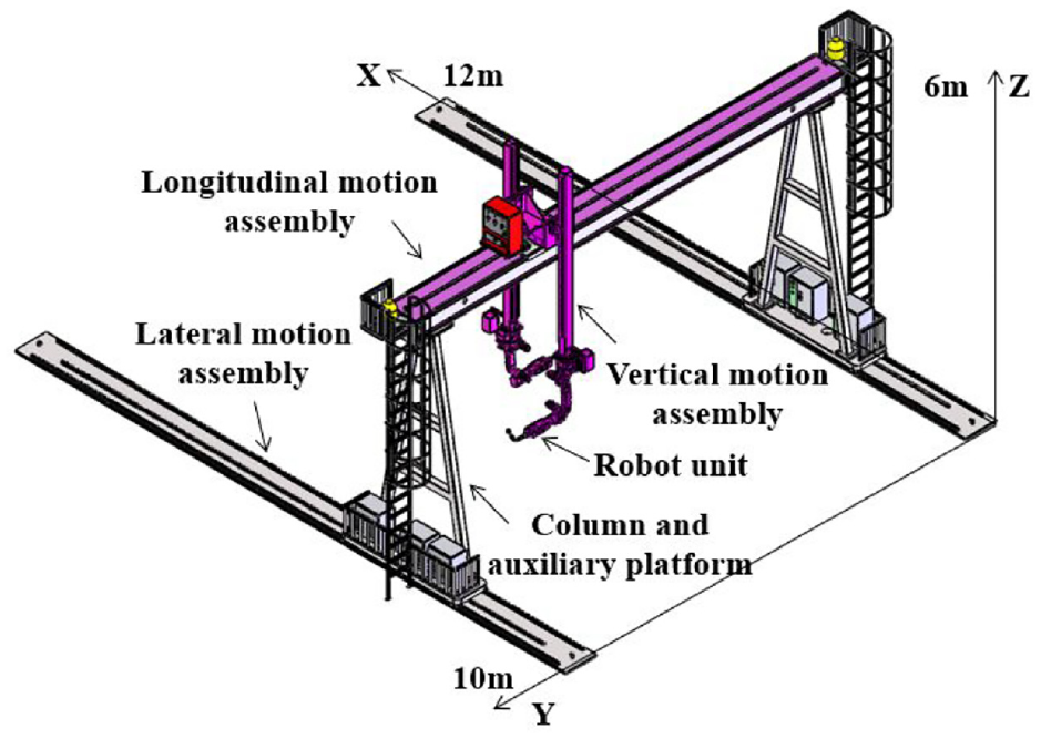
The gantry unit is mainly composed of lateral movement components, longitudinal movement components, vertical movement components, columns, and auxiliary platforms. The lateral motion component is installed on the ground to realize the X-axis movement of the gantry as a whole along the direction of the guide rail, and the length is greater than 10 m; the longitudinal component is installed on the column, which can assist the robot in moving in the Y-axis direction. The main beam is 12 m long and is off the ground. The height is about 6 m; the vertical motion component is installed on the Y-axis of the gantry, and the robot is flipped on its bottom, which can assist the robot in moving in the Z-axis direction. The upright column is connected with the horizontal and vertical moving mechanisms. The auxiliary platform has a simple design structure, is stable and firm, and has a beautiful overall appearance, which can meet the needs of equipment layout and daily operation of personnel. There is one main platform and one auxiliary platform. The main platform is mainly used to ride on various electrical control boxes and the driving part of the active trolley moving in the front and rear directions. The vision unit is installed at the end of the robot, and the scanning, modeling, and tracking functions of the welding seam are realized through the movement of the robot. The robot cell uses a JARI-CP-30 series welding robot. The welding unit consists of a welding power source, a wire feeder and a welding torch. The master control unit consists of a welding intelligent process library, PLC, industrial computer, master control cabinet, and power distribution cabinet.
Operation mode of system joints
The dual-arm welding robot of the welding workstation stands on two guide rails and moves forward and backward within a range of 10 m. The horizontal main beam is about 12 m long and about 6 m above the ground, and the arms can move horizontally independently on the main beam. Each independent arm of the robot can move at a height of 2–4 m from the horizontal main beam. Each robotic arm has six rotating joints, and the control of the six rotating joints can meet the needs of the robot to achieve precise trajectory control according to the welding process. The welding workstation has 17 joints, including 5 sliding motion axes and 12 rotating motion axes. The motion form of each joint is shown in Figure 4.

Joint structure of welding station.
Kinematics analysis
Joint posture changes
The full name of the D-H parameter is the Denavit-Hartenberg parameter, which was first proposed by Denavit and Hartenberg.27–29 It reflects the relationship between various mechanical structures by using connecting rod parameters. This method can be applied to any structure of the manipulator and is not limited by its complexity and structural order. When using the D-H method to establish a robot model, it is necessary to first determine its initial position and posture, and then gradually establish the coordinate system of each joint from the base to determine the D-H parameters. The adjacent joints of the welding station are connected by connecting rods. The description of the pose of the system can be started from the base, transmitted from adjacent joints to the end effector, and an independent coordinate system is established on each joint axis, which is obtained by a homogeneous transformation matrix. The coordinate transformation relationship between adjacent joints.
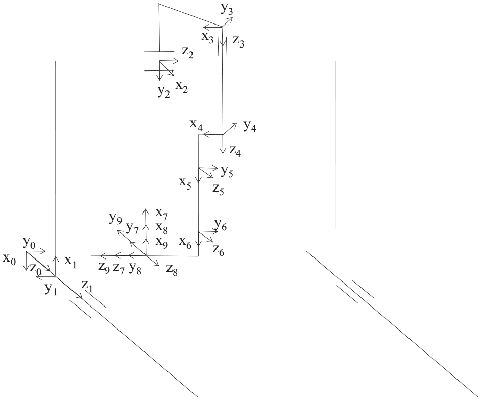
In the welding workstation system studied in this paper, the two cantilevers share the gantry as the only associated degree of freedom, and the other degrees of freedom of the two arms are independent of each other, so the two cantilevers on the beam can be planned separately in the subsequent algorithm. In this way, the original 17-DOF of the system are simplified to 9-DOF of the gantry and the single arm. Define xi—yi—zi as the coordinate system of the ith joint of the gantry frame and the manipulator. The gantry frame has 3 moving joints, and the manipulator arm has 6 rotating joints. The coordinate system of all connecting rods is established, and the D-H coordinate system of the system is established according to the improved D-H parameter method, as shown in Figure 5. Set the origin position of the base coordinate system x0-y0-z0 at the end point of the gantry moving track. The z0 direction is consistent with the forward movement direction of the guide rail, x0 is vertically downward along the gantry, and y0 is along the beam direction to the right. According to the transformation relationship between the joints, the coordinate systems of other joints are established in turn, and the D-H parameters thus obtained are shown in Table 1. The generalized homogeneous transformation matrix between adjacent joint coordinate systems is shown in formula (1). Substitute the D-H parameters in Table 1 into formula (1) to obtain the homogeneous transformation matrix between nine adjacent joints, and then multiply them continuously. The change matrix of the end of the manipulator relative to the base coordinate system is then obtained. Finally, the forward kinematic equation of the welding workstation is obtained, as shown in formula (2).
Joint coordinate system of the robot.
Modified D-H paramater of 9-DOF manipulator.

In the table:


In the equation: c means
Differential kinematics
The Jacobian matrix is to study the linear mapping relationship between operation space velocity and joint space velocity, and can also represent the force transfer relationship between spaces. The linear velocity of the end effector of the robotic arm relative to the base coordinate system and the velocity of each joint are separated from each other. However, in the actual working process of the robotic arm, whether it is the precise positioning of points or the welding of straight and arc welds, the goal of trajectory planning is the end effector, and the motion-controlled actuator is the drive motor of each joint. The Jacobian matrix can establish the relationship between the two types of velocities through mathematical formulas and can also describe the relationship between the contact force and the joint force between the end effector and the outside world. Therefore, the Jacobian matrix and differential kinematics play an important role in kinematics analysis.
The analysis of the welding workstation model shows that the gantry has three moving joints, and its rotational angular velocity is 0. The six joints of the welding robot are all rotary joints, and the last three rotation axes intersect at one point. The vector method is used here to construct its Jacobian matrix. The expression of the moving joint is the same as the formula (3), and the expression of the rotating joint is the same as the formula (4).


The Jacobian matrix of each joint is shown above, and the Jacobian matrix of the gantry double-arm welding robot system can be obtained by stitching it together, as shown in equation (5):

The differential equation of the system can be derived as equation (6):

Simulation verification
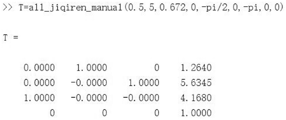
The Robotics Toolbox of Matlab is used to model and kinematically simulate the welding workstation, and the Link and fkine functions are used for modeling and simulation solutions. The movement range needs to be set for the moving joint of the gantry, and the rotation range needs to be set for the rotating joint of the manipulator. Set the input value of each joint as (0.5, 5, 0.672, 0, −π/2, 0, −π, 0, 0). The simulation posture of the manipulator is shown in Figure 6, and the simulation posture of the welding workstation system is shown in Figure 7.

Welding robot simulation model pose.

Welding workstation system simulation attitude.
The attitude matrix of the welding workstation end obtained by using the fkine function of Robotics Toolbox is shown in Figure 8. After programing the positive kinematics equation in Matlab and inputting the same initial joint angle, the resulting end pose matrix is shown in Figure 9.

End matrix solved by robot toolbox.
End matrix solved by theoretical programing.
It can be seen from Figures 8 and 9 that the end matrix solved by the fkine function and theoretical programing is consistent, which verifies the correctness of the modeling and kinematics simulation of the welding workstation.
Weld type and discretization
Weld type
A typical leading group is usually composed of plate parts and stiffeners. When there is a single stiffener, the height of the rib is less than or equal to 600 mm. When there are two stiffeners, the rib plate is perpendicular to the base plate. The workpieces are placed without overlapping, ensuring that the spacing between adjacent ribs meets the corresponding relationship between the spacing and height of the vertical plates. Ribs are installed vertically and horizontally. The vertical and horizontal ribs are perpendicular to each other. There is a straight-line weld between the rib and the bottom plate, and a vertical filet weld between the rib and the rib. After the small group is assembled into the middle group, it contains both normal and reversed plate frame structures, and there is a perpendicular relationship between the plates. Therefore, there are two kinds of filet welds in the middle assembly, which are the vertical plate, the double-sided straight-line welds between the rib plate and the bottom plate, and the vertical filet weld between the vertical plates. When there is a certain radian in some of the plates and ribs standing in the middle and small groups, arc welds are formed. Therefore, typical welds in medium and small formations include: straight-line welds and arc-shaped welds. A typical form of a middle group stand is shown in Figures 10 and 11.

Typical form of sub-assembly.

Typical form of unit-assembly.
Welds in sub-assemblies and unit-assemblies vertical workpieces can be divided into straight-line welds and arc-shaped welds. Weld curves can be classified into three categories: straight line welds formed by the intersection of two space planes, plane arc shape welds formed by space planes and space curved surfaces, and space arc shape welds formed by space curved surfaces and space curved surfaces. The three types of welds can be represented by the general formula (7), and can also be represented by the trigonometric function expression (8) for the convenience of description. Before the simulation analysis, it is necessary to establish the workpiece coordinate system and the welding point coordinate system, and obtain the pose transformation matrix between them. Taking the straight line weld as an example, the established coordinate system is shown in Figure 12.


Schematic diagram of weld coordinate system.
Discretization of weld seams
There are many factors affecting welding quality, such as welding speed, welding torch posture, arc voltage and current, etc. Arc current mainly affects the depth of penetration. Arc voltage mainly affects the weld width. The adjustment of the torch attitude depends on the relative position of the welding seam; Welding speed refers to the length of weld completed in unit time, and is also the relative speed between welding gun and weld. In order to ensure uniform welding speed and welding quality, for continuous weld, it is necessary to discretize the weld, including the discretization of position and posture. In this case, the welding linear velocity V0 is constant and its size is determined by the welding process. A series of weld discrete points are generated by the velocity V0 and the interpolation period T. Attitude discretization to define the welding gun linear velocity direction, generally along the direction of the weld.
Discretization of linear welds
Let the starting point of the weld be p1 = (x1, y1, z1), finish for p2 = (x2, y2, z2).
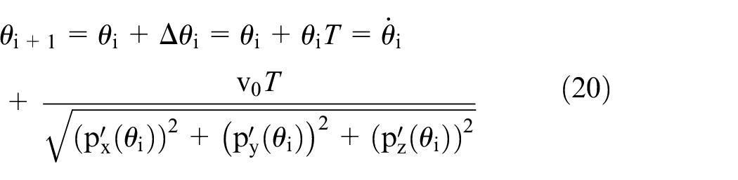
The direction vector of the weld can be expressed as n = (x1 − x2, y1 − y2, z1 − z2), V0 is the welding speed, T is the interpolation cycle. The coordinates of discrete points at Pi position can be obtained from the previous weld point Pi − 1:

The equation of a straight line in space can be represented by two plane equations

Then the normal vectors

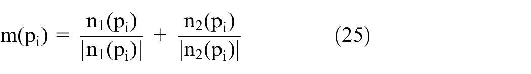
The Z-axis direction of the weld coordinate system is the angular bisector direction m of the normal vectors

The unit vectors u, v, and w of the three axes of the discrete point coordinate system of the weld can be expressed as:

Combining the above formulas, the pose transformation matrix of the discrete points of the weld and the workpiece coordinate system can be obtained as:

Discretization of arc-shaped welds
The position expression of the coordinate system of discrete points of the weld is:

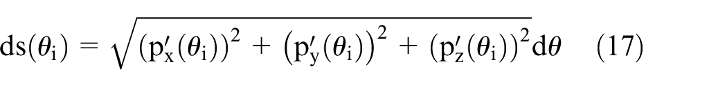
The formula of arc length is:

The arc differential formula is:


Then the position coordinates of the discrete point Pi of the weld are:

The expression of the space curve is:

The tangent vector at the discrete point Pi of the weld can be expressed as:

The normal vectors n1 and n2 of the surfaces on both sides of the weld can be expressed as:

The axis direction of the welding seam discrete point coordinate system can be expressed as:
The unit vectors u, v, and w of the three axes of the discrete point coordinate system of the weld can be expressed as:

Combining the above formulas, the pose transformation matrix of the discrete points of the weld and the workpiece coordinate system can be obtained as:

Generation of welding track
The welding trajectory planning simulation is carried out for the straight line weld and the arc-shaped weld in the middle and small groups. First, the physical constraints of the welding workstation system are determined, and then the priorities of different joint movements are divided, and then the two-arm coordination problem is considered according to the weld type., decouple the dual-arm system into a single-arm system for separate planning, and finally perform a visual simulation of trajectory planning based on Matlab’s Simscape Multibody. The simulation flow chart is shown in Figure 13.

Simulation flow chart.
Constraints
The welding manipulator system studied in this paper mainly contains two types of constraints from the point of view of actual physical constraints. These constraints are input as constraints during simulation.
(1) Constraints on upper and lower limits of joint movement and rotation speed caused by the running speed of the driving motor;
In the welding workstation, each joint is equipped with a stepper motor, and the joint motion is driven by the motor. Commonly used stepper motors include two-phase and three-phase synchronous or asynchronous motors. Generally, the absolute values of the upper and lower limits of the motor drive speed are the same, but the signs are opposite. The motor parameters referred to in the literature are as follows: maximum speed 170 mm/s, maximum acceleration 170 mm/s2, rated power 1.5 kW, rated speed 3000 r/min. The maximum angular velocity of each joint of the manipulator is 180°/s, the maximum acceleration of motion of each joint is 180°/s2.
The joint velocity constraint can be expressed as:

(2) Constraints on upper and lower limits of joint movement range caused by joint limit of the system;
In the ship welding workstation, there is a certain range for the moving distance of the gantry and the angle of the rotating joint of the robotic arm. This range is determined by the physical structure of the system and the requirements of the mechanical system characteristics. For the moving range of the translational joint of the gantry frame, it is necessary to refer to the effective running length of the link in the coordinate system. Take the system as an example, in the structural design, the gantry frame as a whole along the guide rail to achieve the X-axis movement range of about 10 m. The length of beam of Y-axis is 12 m, and the mobile range of horizontal joint is about 10 m considering devices such as door frame column auxiliary platform. Due to the principle that both arms are divided and no crossing is allowed, the effective mobile range of single manipulator joint on Y-axis is about 5 m. The Z-axis movement range is about 4 m above the ground. For the rotary joint of the manipulator, its motion range has been given in Table 1.
For translational joints, its position constraints can be expressed as:

For rotary joint, its position constraint can be expressed as:

Division of exercise priorities
For ship welding workstations, the main function of the gantry is to quickly adjust the posture in a wide space. The inverted mechanical arm is mainly used for the precise adjustment of the end posture. Different task types can be combined by different joints according to their kinematic characteristics. This eliminates the duplication of joint functions and provides a new idea for welding trajectory planning. The motion accuracy of the gantry body, the adjustable joint of the gantry, and the inverted two 6-degree-of-freedom welding manipulators are different. For different task types, the three joints can be further classified.
The motion priority of the ground guide rail of the gantry frame is the lowest, which is used for fast initial positioning. In ships, small groups of parts are usually quite large in size, perhaps several meters. In the initial stage of welding positioning, the gantry frame and manipulator system are in the initial state of 0, and the distance from the target workpiece is far, requiring the gantry frame body to move and position quickly. The movement range of the ground guide covers the entire operating space of the manipulator, which is the most suitable for the initial positioning task. When the gantry frame moves, it must bear the weight of the whole system. The moving cost is high, and the moving speed is restricted to some extent.
The priority of the horizontal prismatic joint and vertical prismatic joint on the beam is in the middle. They are often used for auxiliary positioning and can make up for the deficiency of adjusting position when the gantry joint moves alone. These two joints are loaded with an arm of the robotic system, and the cost of motion is slightly lower than the doorframe joints. However, its driving mode is the same as that of the gantry joint, and its motion accuracy is the same as that of the gantry joint according to its mechanical characteristics. There is still a big gap compared with the 6-DOF welding manipulator.
The rotary joint motion of the manipulator has the highest priority. Due to the high speed and high precision, the conventional welding task is usually completed by the inverted welding manipulator under the vertical prismatic joint. There is no redundancy in the six rotary joints and their positions are easy to determine. There is no conflict with the three translational joints of the gantry, and the welding task can be completed quickly.
Simulation and discussion
For the typical straight-line welds and arc-shaped welds in the workpieces of sub-assemblies and unit assemblies, taking the small rib and bottom plate of the topside tank as an example, as shown in Figures 14 and 15, the robot welding trajectory planning research is carried out. Simplify the welding workstation model established by Solidworks, define the relative position of the workpiece and the welding workstation through position constraints, and then import the Simcape module of Matlab in the form of an XML file, and the built simulation environment is shown in Figures 16 and 17.
(1) For straight-line welds, usually two robotic arms perform dual-gun welding on different sides of the same weld. Take a straight line weld on the small floor of the topside tank as an example, and the same method is used for other straight line welds. The main process of trajectory planning for straight-line welds are as follows:
Step1: The gantry returns to the origin of the guide rail;
Step2: Adjust the gantry position. According to the division of joint motion priorities, the gantry ground rails are used for rapid positioning, and the horizontal and vertical joints are used for auxiliary positioning, so that the weld seam of the welded workpiece is within the reachable space of the two welding robots;
Step3: Adjust the pose of the dual robotic arms. Decouple the dual-arm system into a single-arm system and plan separately and adjust the poses of the two robotic arms so that the welding torch faces the welding seam and moves to the starting point of the welding seam;
Step4: According to the target weld path, decouple the dual-arm system into a single-arm system and plan separately. The selection of the inverse solution of the manipulator in Cartesian space is based on the principle of “weighted summation.”“Weighting” refers to assigning different weight coefficients to different joints. The first three joints of the robotic arm are large joints, and the last three joints are small joints. Based on the principle of “move more small joints and less large joints,” different weight coefficients are set for different joints; “adding” means selecting a set of solutions with the least amount of joint change. The core of the method idea is to assign different weight coefficients to different joints and minimize the sum of joint rotation angles, which can be expressed by the following formula. The inverse solution optimization is performed on the manipulator, and the welding is completed from the starting point to the end point of the weld.


Small floor of the top side tank.

Bottom plate.

Simulation environment of welding workstation.
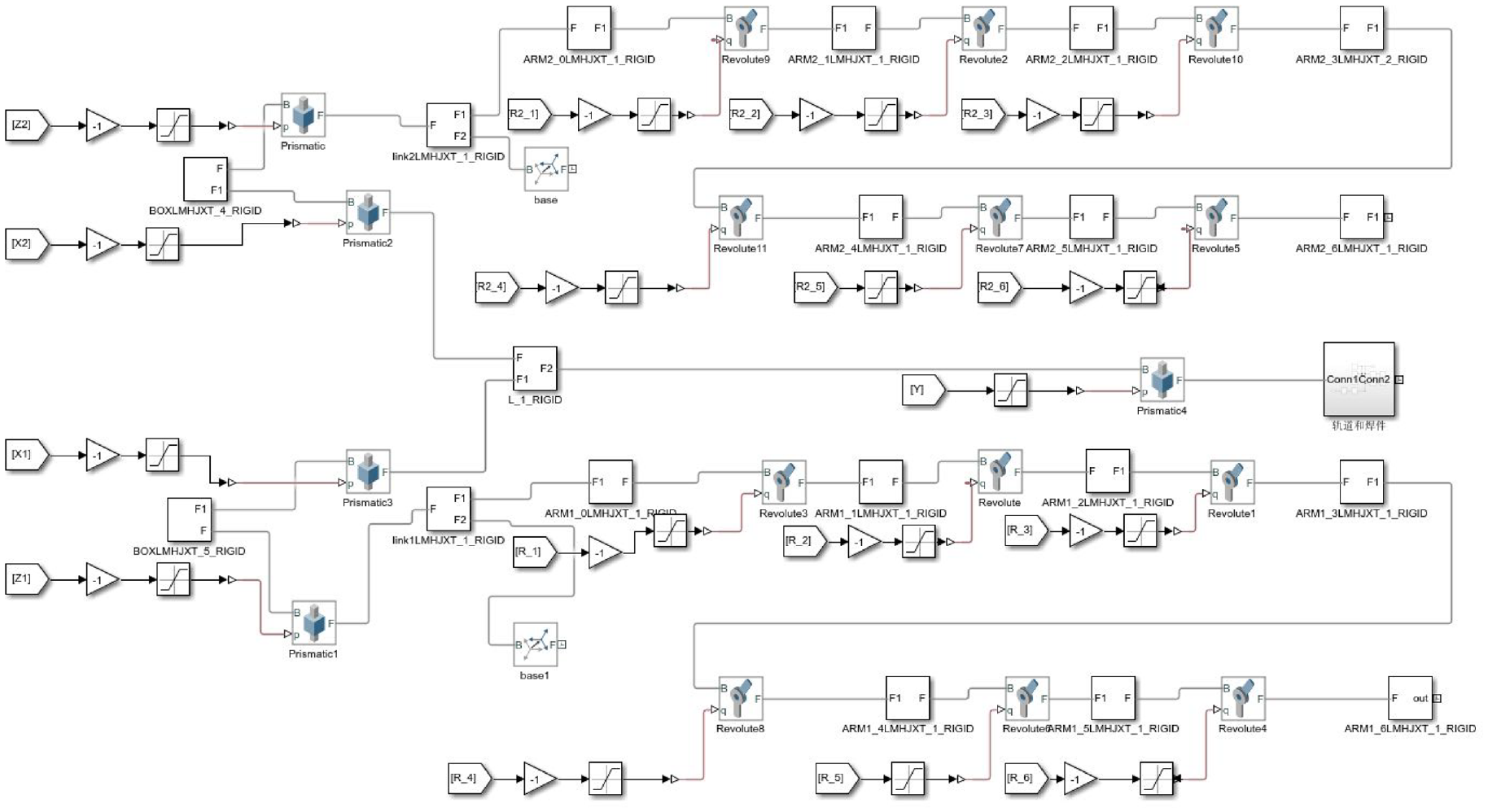
Simulink model.
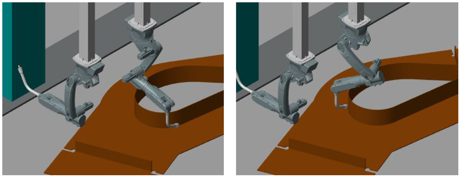
The simulation is carried out according to the above process, the welding process diagram is shown in Figure 18, and the angle change of each joint of the double manipulator is shown in Figure 19.

Welding process diagram.

Joint curves of two robots.
The whole simulation process is divided into three sections. The ground rail of the gantry is moved to a suitable position, the robot arm adjusts the initial welding posture, and the robot arm completes the welding from the starting point to the end point of the welding seam. Figure 19 shows the curve of each joint value information of the robot. It can be seen that during the simulation process, the two manipulators keep synchronized during the welding process, and the joints of the manipulator change smoothly without sudden change, indicating that the two manipulators are in the simulation process. It can run smoothly to complete welding tasks.
(2) For arc-shape welds, the arc-shape weld on the base plate is single-sided, and one side of the weld is finely welded by a single robotic arm. Taking an arc-shape weld seam on the base plate as an example, the trajectory planning of it is studied, and the main process is the same as that of straight-line welds. The welding process diagram is shown in Figure 20, and the angle change diagram of each joint of the manipulator is shown in Figure 21.
Welding process diagram.

Joint curves of robot.
The whole simulation process is divided into three sections. The gantry moves to the appropriate position, the robotic arm adjusts the initial welding posture, and the robotic arm completes the welding from the start point to the end point of the weld. Figure 21 shows the curve of each joint value information of the robot. It can be seen that in the simulation process, the first five joints of the robot arm change smoothly during the welding process, the fluctuation is small, and there is no obvious mutation. Although joint six has changed greatly in the figure, it is because its range of change is ±180°, and the value has changed abruptly. The rotation direction is rotated from the specified negative angle area to the positive angle area, and the actual welding process is continuous. There is no obvious mutation. The robotic arm can run smoothly to complete the welding task during the simulation process.
Conclusion
In the shipbuilding industry, there are many sub-assemblies and unit-assemblies, many types of welds and complex flow directions, and the degree of automation of welding is low. When performing welding operations, a gantry frame is required to cooperate with a robotic arm to complete the welding operation. The gantry extends the moving distance in the three-axis direction and increases the flexibility of the system, but there are also problems of joint redundancy and double-arm coordination. Aiming at this problem, the strategy of decoupling the dual-arm system into a single-arm system is adopted to plan separately and distinguish different joint motion priorities. The welding trajectory planning and simulation of various types of welds are carried out using typical sub-assemblies and unit-assemblies as research objects. The main conclusions are as follows:
The three-dimensional model of the sub-assemblies and unit-assemblies welding workstation of the ship was established by using Solidworks. Its structure, joint operation mode, and degrees of freedom are analyzed. Using the improved D-H parameter method and differential kinematics theory, the kinematics model and differential kinematics equation of the workstation system are established, and the angular velocity and linear velocity of the end-effector of the manipulator in the task space are linked with the motion velocity in the joint space. Finally, the correctness of modeling and kinematics simulation is verified by using the robot toolbox of Matlab.
The typical forms of sub-assemblies and unit-assemblies workpieces and different types of welds are analyzed, including linear welds and arc welds, etc., and the pose discretization analysis of the welds is carried out.
For the typical straight-line and arc-shaped welds in ship sub-assemblies and unit-assemblies, taking the welds on the small floors and bottom plates of topside tanks as examples, the research on welding trajectory planning is carried out. The dual-arm coordination and redundant degrees of freedom problems are solved by decoupling the dual-arm system into a single-arm system to plan separately and prioritize different joint motions. Considering the actual physical constraints, a visual simulation is carried out through the Simscape Multibody of Matlab. The simulation results show the effectiveness of the strategy, which has certain reference significance for the on-site welding of shipbuilding.
Footnotes
Handling Editor: Chenhui Liang
Declaration of conflicting interests
The author(s) declared no potential conflicts of interest with respect to the research, authorship, and/or publication of this article.
Funding
The author(s) disclosed receipt of the following financial support for the research, authorship, and/or publication of this article: This research was funded by High-Tech Ship Scientific Research Project from the Ministry of Industry and Information Technology ([2019]360) and Zhengzhou University Youth Talent Enterprise Cooperative Innovation Team Support Program Project (2021).