
Abstract
A stainless steel flux for manual metal arc welding (MMAW) has been developed. The coated electrode is a rutile electrode whose basic components are titanium (IV) oxide and stainless steel powder. Some of the other components were substituted; the more popular but expensive potassium silicate binder was replaced with readily available sodium silicate binder. For the binder to perform effectively, it was enriched with potassium carbonate, which was sourced locally from palm bunch. Cellulose, a good gas former was replaced with starch, which was gotten from cassava. The components were sieved into 75 µm particle size. The experimental design was set up using Central Composite Design in Design Expert software. The design varied the percentage composition of calcium carbonate, binder, titanium (IV) oxide, silicon (IV) oxide, and stainless steel powder. Twenty-six (26) test samples were produced using the central composite design tool of the design expert software and tested for tensile strength. The experimental results were analyzed and optimized using Response Surface Methodology and Validated using the ANOVA tool of the Design Expert software. An optimal composition of 10% CaCO3, 13% Binder, 13% Titanium oxide, 12% silicon (IV) oxide, and 36% stainless steel powder were obtained to give a corresponding 539.7 N/mm2 tensile strength.
Introduction
The saying that “No welding, No industry” is a true fact seeing that welding is one of the more basic forms of metal joining. Even with the increasing trend in the introduction of composite materials into our everyday products, metals still remain very important to the society especially when it has to do with the support of structural members, thus making the need to join metals an indispensable production operation. Manual metal arc welding is one of several fusion processes for joining metals and it is the most widely used in developing economies. 1 By applying intense heat, metal at the joint between two parts is melted and caused to intermix directly, or more commonly, with an intermediate molten filler metal. Upon cooling and solidification, a metallurgical bond is created. The use of bare electrode causes the oxidation of the weld metal which in turn has an adverse effect on the weld, thus creating the need to protect this condition. To prevent this condition of oxidation from occurring, the use of flux becomes very important. 2 Flux is a material used to prevent, dissolve or facilitate the removal of oxides and other undesirable substances. Shielded metal arc welding (SMAW), also known as manual metal arc welding (MMAW), flux shielded arc welding or informally as stick welding, is a manual arc welding process that uses a consumable electrode covered with a flux to lay the weld. 3 The flux generates gases which protects the weld and shield it from harmful atmospheric oxygen, nitrogen, and any other contamination. There are over 100 different raw materials used in the production of welding electrode fluxes. These materials perform different functions and have several characteristics for which they are easily identified.
Researchers have discovered that the quality of the weld and the increasing strength of the resulting welds are being influenced by each chemical constituent element of a flux. There are several flux/coatings compositions. The composition selected depends on its utility. Arun and Randhawa 4 in their research work said that Achebo 5 observed that various manufacturers have produced different flux compositions depending on the weld strengths they intend to achieve; this being the criterion for developing their own unique flux compositions. Welding flux design is one of the key areas of arc welding technology that require improvement because the weld-metal quality, productivity of the welding process and economical weld production depend largely on the flux formulation. Operational characteristics such as arc initiation and stability, minimum spatter, positional welding, high deposition rate, penetration, and bead morphology are influenced by the welding flux formulation. The quality of weld-metal is often evaluated by many characteristics such as chemical composition, mechanical properties, bead profile and microstructure. Studies have shown that these characteristics are influenced by the welding flux formulation; therefore it is important to select the right type of welding flux ingredients and choose the appropriate proportions of the various flux ingredients to attain a good weld-metal quality. 4
The components in this work are bye products of different local manufacturing processes within our environment. There is a need to combine these components together in appropriate quantities to form an acceptable blend of flux. There are over 100 (100) materials used in the production of welding electrode fluxes. These materials perform different functions and have several characteristics for which they are easily identified. The gas forming operation of the flux is mainly done by cellulose, calcium carbonate, and some little percentage of other components. Most frequently in the past, components such as iron II oxide, silicon IV oxide, and calcium fluoride (flouspar) have been used as slag formers. In addition to these, titanium oxide and potassium carbonate were used as arc stabilizers. There are other constituents which though very little in percentage contribution have great effect in the formulation. These include the alloying substances such as ferro-chrome, ferro-manganese, and ferro-silicon which also act as deoxidizers. The most popular binder is potassium silicate. Glycerin, sodium silicate, organic gum, and plastic have also been used in the past as binders. 6
In this work cerium oxide was introduced as one of the raw materials for the formulation of the new flux for stainless steel electrode, in addition to the bye products of different local manufacturing processes within our environment.
Materials and method
The development of welding flux requires quite a number of materials as well as distinct production procedures.
Materials
The materials used in compounding fluxes must be of very high purity (at least 85% pure). Impurities like sulfur and phosphorus will produce poisonous fumes that are harmful to man. In addition, impurity can occur in the form of iron sulfide (FeS2). Effort will be made as much as possible to acquire very pure materials free from contamination. The major reasons for purifying the raw materials are to avoid: corrosion of the filler rod, improper fusion of metals, explosion, poor production of weld, and production of dangerous/hazardous fumes during welding.
The materials utilized for the flux development are;
Starch
Starch was used as a substitute for cellulose. It is easily obtainable in all the carbohydrate storing food products. Cassava tubers being readily available were obtained, washed, peeled and sent for processing. At the end of the processing, a good product was obtained with more than 80% starch content.
Silica
Fresh water sand was collected from the bank of River Niger. This sand was washed with tetraoxosulfate (VI) acid until it was clean and then was dried.
Cerium oxide
Cerium is most heavily used in the form of mischmetal for metallurgical purposes. Cerium is the major component of mischmetal (50%–75% by weight for the most common grades), a commercial mixture of metallic light lanthanides prepared by the electrolysis of mixed lanthanide chlorides and fluorides obtained from bastanite or monazite. Mischmetal reacts with the impurities found in metals to form solid compounds, thereby reducing the effect of these impurities on the properties of the metal. The cerium oxide that was used was bought at Onitsha.
Limestone (CaCO3)
The calcium carbonate that was used was obtained from purified limestone from deposits found in Nigeria. It was bought at Onitsha.
Magnesium oxide
This is a fine white powder obtained by calcining (to heat to a high temperature without fusing in order to drive off volatile matter or to effect changes) magnesite or dolomite (CaCO3MgCO3) and refining chemically. It is usually called magnesia. It offers some good thermal resistance, high electrical resistivity and moderately high thermal conductivity and is relatively easy to be sintered. The magnesium oxide that was used was bought at Onitsha.
Sodium silicate
Sodium silicate is made by strongly heating two part by mass of silicon oxide with one part by mass of sodium trioxocarbonate until the mixture melts.
The sodium silicate that was used was in the form known as water glass. Water glass is obtained by dissolving sodium silicate in hot water under pressure to form a viscous liquid which solidifies on exposure to air. The sodium silicate was bought at Onitsha. Sodium silicate and potash were used as binder so as to eliminate the use of potassium silicate which is not manufactured in Nigeria.
Other products
Other items that will be used as directly purchased from the market are aluminum oxide (from aluminum smelting industry Ikot Abasi ALSCON), chromium oxide, nickel oxide, core wire/rod (from Ajaokuta steel complex), and stainless steel powder which was bought from China.
Methods
The methods for the formulation of the flux include the following;
Flux formulation and compounding
Flux formulation and compounding involves sorting out the appropriate flux elements and mixing them in their right proportions to achieve a required composition. In order to achieve this objective, an intensive research was carried out on each component, its primary and secondary functions, appropriate percentage composition, and the possibility of sourcing it locally in the country. The functions of the materials are presented in Table 1.
Material components and their respective functions.

Manufacturing method
This involves the methodology adopted to produce the test specimen. The apparatus and the materials that were utilized in the production process include; flux material (compounded), binder (sodium silicate), weighing balance, 75 μm sieve, mortar and pestle, core wire (gage), and gage mold.
The component materials were sieved to their required sizes into a tray using a 75 μmsieve. This process was carried out for all the flux materials that have higher than the recommended size. The optimized value of each material was weighed out in a 250 cm3 beaker and poured into a mixing mortar. The batch was thoroughly mixed to produce the flux paste. The compounding and compaction was carried out in a mortar to ensure proper and thorough mixing. This gave rise to a compact paste devoid of air bubbles. The paste was filled into both halves of the mold. The appropriate filler rod was inserted in the corresponding mold in such a way as to obtain maximum concentricity. This is necessary because eccentricity does not allow for arc stabilization during the actual arc welding. The two-halves were closed and subjected to clamping force to remove excess flux paste. The mold was opened and the fresh molded electrode was taken out.
The fresh molded electrode was allowed in the open air for a day to absorb CO2 and also dry up. The dry electrode stick was baked in an oven at a regulated temperature of 350°C for 1 h. The thoroughly baked electrode was removed and allowed to cool down in an environment after which it was thoroughly wrapped to avoid moisture absorption. After this a series of test was carried out in order to know the quality and reliability of the electrode. The tests include tensile strength so as to determine the tensile strength of the weld deposited by the electrode, performance test in order to determine the arc stability and efficiency, as well as the position test carried out in order to determine the suitable welding positions for the electrode.
Design of experiment
The Central Composite design tool of the design expert 10 software was used to design the percentage composition of the test samples. A total of 26 runs were obtained from the design as shown in Table 2. The factors considered are the percentage composition.
Experimental factors and response in the development of the flux.

Factors and response
The factors and response considered in the development of the flux is shown in Table 2. Five factors were considered in the designs which are the percentage composition of CaCO3, binder, Titanium Oxide, Silicon (IV) oxide, and Stainless steel powder while tensile strength was the response considered in the experiment. The design gave rise to twenty six (26) experimental runs comprising of twelve (12) core points, nine (9) star like points, and five (5) center points. The responses obtained from various runs are significantly exceptional, (Quadratic) which implies that each of the factors have substantial effect on the response.
Tensile strength test
The welded joints were created on tensile steel plates using the developed electrode samples. The welded samples were then cut into the designated shape as seen in Figure 1, to enable firm grip by the jaws of the universal testing machine. The samples are 15 cm long, with grip ends of 4 cm by 2 cm. On gripping the samples on both ends, they are pulled slowly until they fracture. The test is performed under room temperature.

Tensile test samples.
Microstructural analysis
The Scanning Electron Microscope was used to study the microstructural analysis of the welded joints. Two stainless metal sheets were welded together and 5 × 5 cm section, with the welded joint at the middle was cut out as test samples. Test samples were created for both the new flux formulation and existing E308H-16 electrode.
Results and discussion
Central composite design
The design matrix of the Central Composite Design is presented in Table 2.
Fit summary and ANOVA for the CCD
The Analysis of Variance (ANOVA) was used to interpret the Central Composite Design. With the aid of the Analysis of Variance the F-value tests were performed to estimate the significance of the various models. The result of the F-value helps to identify the highest order model, with significant terms.7,8 This highest order model predicts the most accurate relationship between the factors, hence is chosen. Lack-of-fit test measures the adequacy of the different models based on response surface analysis.9,10 The obtained Model F-value of 131.55 implies the model is significant. There is only a 0.01% chance that an F-value this large could occur due to noise.
Final equation in terms of actual factors
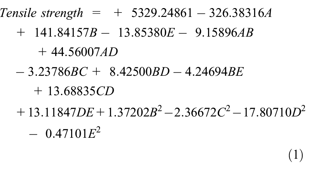
The equation in terms of actual factors can be used to make predictions about the response for given levels of each factor. In a regression equation, when an independent variable has a positive sign, it means that an increase in the variable will cause an increase in the response while a negative sign will result in a decrease in the response. 11 Hence, a decrease in CaCO3, increase in binder, decrease in titanium oxide, decrease in silicon (IV) oxide and decrease in stainless steel powder will cause an increase in the tensile strength. The Binder will have more significant effect in the increment of the response since its coefficient is the highest. Eliminating the insignificant terms, the final model for tensile strength is represented in equation (1).
3D response surface plots
The 3D response surface plots for Tensile Strength are shown in Figure 2. The plots show a minimum and maximum tensile strength of about 400 and 650 MPa respectively, with the composition of the factors CaCO3, Binder, Titanium oxide, Silicon (IV) oxide, and stainless steel powder ranging from 8%–10%, 13%–18%, 13%–18%, 10%–12%, and 30%–36% respectively which is in accordance with the model.

3D surface plot for flux development showing combined effects of the factors: (a) CaCO3 versus silicon (IV) oxide, (b) Titanium oxide versus binder, (c) Stainless steel powder versus binder, and (d) stainless steel powder versus silicon (IV) oxide.
The 3D response surface plots are graphical representation of the interactive effects of any two variables of the factors. The plots show that all the considered constituents have an effect on the tensile strength of the developed electrode. The stainless appears to have a more pronounced effect which is positive in nature on the tensile strength. This can be deduced from Figure 2(c) and (d). The effect of CaCO3 and silicon is also seen from Figure 2(a) to be positive up to a tensile strength of about 560 N/mm2, after which the effect becomes negative. The same trend of effect can also be concluded for titanium oxide and binder as seen in Figure 2(b).
Optimization of the central composite design
The optimization of the factors was done using the optimization tool of the design expert software. The factors (CaCO3, Binder, Titanium oxide, Silicon (IV) oxide, and stainless steel powder), were set within range as initially imputed for the experimental design. For the response, tensile strength was set within the range set in the initial design of the experiment. The selected solution show factor levels of 9.655% CaCO3 content, 17.770% Binder content, 16.010% Titanium oxide content, 10.757% silicon (IV) oxide content, and 32.956% stainless steel powder content. Thus, the actual optimized composition is 10% CaCO3, 13% Binder, 13% Titanium oxide, 12% silicon (IV) oxide, and 36% stainless steel powder. With the factor levels given, a response of 539.7 N/mm2 tensile strength was obtained.
Scanning electron microscopy (SEM)
The micro structural analysis of the welded portion of stainless steel done with the developed electrode was conducted using the Scanning Electrode Microscope. Figure 3 presents a SEM image of the welded portion. The figure shows a little number of black spots. This indicates that there is little carbon inclusion, thus making the developed flux composition a good one. Compared to the SEM image of the existing formulas shown in Figure 4, a better continuous flow is observed for the new formulas. This indicates it will give a better carbon/particulate inclusion free weld than the existing formulas. The circled portion of the SEM images show areas of observation. Comparing the circled areas on the two SEM images, fewer particulate inclusion is noticed on the part of the newly developed flux. This goes to show that the introduced additives reduced the formation of particulate inclusion.
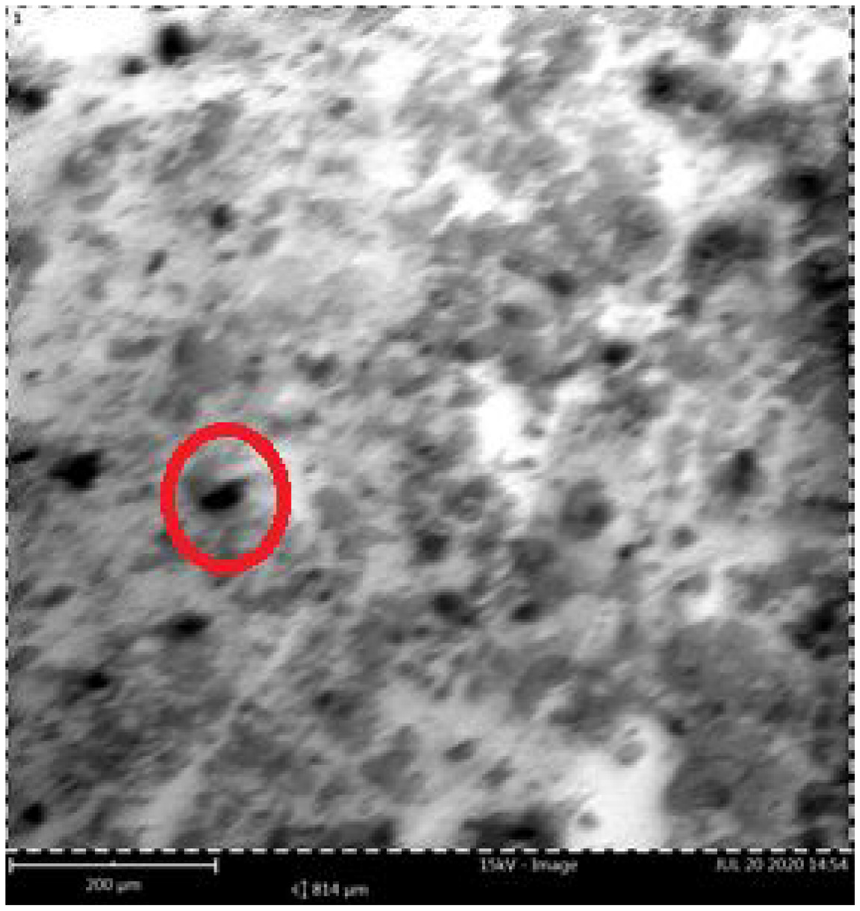
SEM image for welded area for new formulation.

SEM image of welded area of control formulation.
Comparison with existing results
The comparison of the optimized result obtained from the new formulation and those developed with the use of other materials by Ugoamadi 12 is shown in Table 3. It could be seen that the tensile strength of 539.7 N/mm2 obtained in the new formulation is close to that of the foreign electrode, also reported by Ugoamadi. 12
Tensile strength of optimum formulation and other flux formulations.

FTIR analysis
FTIR spectrum of the welded areas for the existing (E308H-16 electrode) and new flux formulations are shown in Figures 5 and 6 respectively. The IR spectra indicates one significant absorption peak at 916.9 cm−1 and 909.5 cm−1 for the welded areas of the existing and new flux formula respectively. Both absorption peaks are assigned to the C-H Vinyl functional group. 13 The similarity between the FTIR spectrum of the new flux formulation and that of the existing formulas, shows that the C-H Vinyl functional group is common for stainless steel electrodes of this nature.

FTIR spectrum of welded area for existing flux formulation.

FTIR spectrum of welded area for new flux formulation.
Conclusion
This study saw the formulation of a new flux for welding stainless steel using manual metal arc welding. The design varied the percentage composition of calcium carbonate, binder, titanium (IV) oxide, silicon (IV) oxide, and stainless steel powder to estimate the thermo-mechanical properties of the stainless steel plate joined with the re-engineered electrode. The optimization result gave an optimal percentage composition of 9.655% CaCO3 content, 17.770% Binder content, 16.010% Titanium oxide content, 10.757% silicon (IV) oxide content, and 32.956% stainless steel powder content. Thus, the actual optimized composition is 10% CaCO3, 13% Binder, 13% Titanium oxide, 12% silicon (IV) oxide, and 36% stainless steel powder. With the factor levels given, a response of 539.7 N/mm2 tensile strength was obtained.
Footnotes
Handling Editor: Chenhui Liang
Declaration of conflicting interests
The author(s) declared no potential conflicts of interest with respect to the research, authorship, and/or publication of this article.
Funding
The author(s) received no financial support for the research, authorship, and/or publication of this article.