
Abstract
To study the axial compression performance of precast circular semi-continuous concrete-filled steel tube (PCSCFST) column, a total of 17 specimens were prepared and tested, including 13 PCSCFST columns and 4 continuous CFST columns. This PCSCFST column is made up of upper and lower steel tubes and outer steel tubes connected by bolts, which has the advantages of easy factory production and convenient transportation. The results showed that shear failure occurred in continuous CFST columns, but not in PCSCFST columns, bolts had obvious influence on failure mode. Maintaining the consistency of the thickness of each steel tube on the specimen can not only improve the local buckling, but also avoid the short plate effect to give full play to the material performance. Moreover, with the increase of steel tube thickness, concrete strength, bolt diameter, reduction of specimen length and pure bolt connection instead of bolt and weld combination connection, the deformation resistance of bolts and axial compression performance of specimens had been enhanced. However, the increase of bolt diameter from 12 to 18 mm resulted in a better strength degradation rate, but worse bearing capacity and deformation resistance. Finally, the predictions of the ultimate bearing capacity of PCSCFST columns under axial compression agree well with the test results, the average value of Nexp/Npre and the variance are 0.998 and 0.00111.
Keywords
Introduction
Relying on its high strength, high ductility, excellent seismic resistance, and rapid construction concrete-filled steel tube (CFST) members have been widely used in high-rise buildings, industrial buildings and arch bridges.1,2 Meanwhile, research researches efforts on CFST columns have been devoted to better promoting its application and development in engineering structure. Moreover, the research of CFST had made considerable progress in terms of shape and structure, as well as compression methods and research methods in recent years.3–12
Du et al. 13 discovered the bottom of the steel tube is prone to local buckling. And as Lai and Ho’s 14 research reported in 2012, as steel dilates more than concrete, the imperfect interface bonding during initial elastic phase, which results in the reduction in the elastic strength and also the initial stiffness. Furthermore, Wei et al. researched that high-strength steel wire can effectively restrain and delay the local buckling of steel tubes in CFST columns. 15 As reported in the author’s previous research, 16 spiral reinforcement can considerably improve ductility but cannot increase the bearing capacity. However, Ding et al. 17 proved welding the stirrup cage to the inner wall of the steel tube not only can considerably enhance the seismic performance of specimens under high axial force ratio, but also overall stiffness, maximum bearing capacity and hysteretic energy dissipation capacity.
The abovementioned studies show that the current research has been mainly focused on investigations of continuous CFST, but the mechanism of mechanical properties of precast CFST is scarce. Moreover, precast buildings have developed rapidly duo to its main advantages, which included high efficiency, high precision, excellent quality, and environmental protection characteristics in recent years. It is easy to find that the joint has a great influence on the performance of the fabricated component. 18 However, the conclusion that poor design of the connection between beams and columns and poor design details of structural members led to the collapse of precast and reinforced concrete systems was reported.19–21 To solve the above motioned problems, much efforts has been directed toward the research on the connection of precast members, including the study of precast pin dowel connections and precast semi-rigid and rigid dowel connections.22–29
Meanwhile, many researches on precast CFST structures are focused on analyzing the assembly problems or joints of two or more members, rather than the assembly problems of the members themselves, which is a pity, just as proposed by Ding et al., a new connection system between steel beams and CFST columns with satisfactory rigidity and bearing capacity is used to connect steel beams in two directions with the help of pre-welded side plates on the column. 30 In order to solve the shortcomings of the continuous CFST columns: (1) it cannot be precast during construction and has poor flexibility; (2) it is hard to transport; (3) it is not environmentally friendly. Thus, a new type precast circular semi-continuous concrete-filled steel tube columns (PCSCFST) columns that members can be easy to produce in the factory and easy to transport in application, which made up of upper and lower steel tubes and outer steel tubes connected by bolts came into being, as shown in Figure 1.

Components of PCSCFST: (a) before assembling (b) after assembling.
In this paper, the mechanical properties of PCSCFST columns under axial compression are studied. By considering the influence of parameters such as connection method, bolt diameter, upper and lower steel tube and outer tube thickness, core concrete strength and steel tube length on the mechanical properties of PCSCFST columns, the failure form, ultimate bearing capacity, load-displacement curve and stress-strain curve of the specimen were analyzed accordingly. Then, the ultimate bearing capacity strength model of the PCSCFST columns was established.
Experiment program
Test specimen
In this study, a total of 17 specimens were prepared and tested, including 13 PCSCFST columns numbered PCSCFST1–PCSCFST13 with different tube thickness and length, different outer tube thickness, connection method, concrete strength as well as four continuous CFST columns numbered DBCS1–DBCS4 with different tube thickness and concrete strength as the control group. Table 1 shows the details of all specimens. Especially, the steel tubes are compact enough. These dimensions are selected in order to maximize the consideration of existing conditions and better serve the research. And the dimensions in the table are shown in Figure 2. All specimens were cast by pouring core concrete into upper and lower tubes, outer tubes and continuous tubes. After curing the columns for 28 days in the laboratory, the PCSCFST assembly procedure was followed. Different types of CFST columns in this paper are shown in Figure 3.
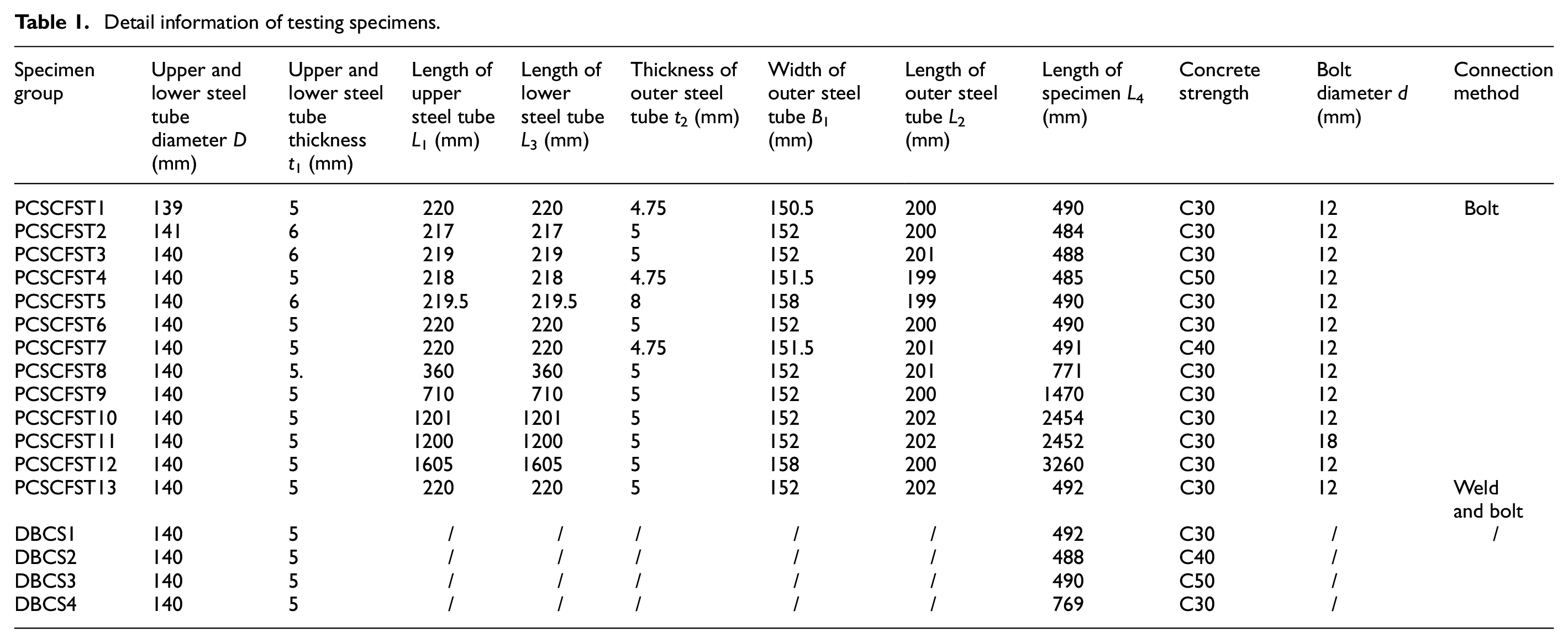
Detail information of testing specimens.

Detail information of specimen size.

Types of CFST columns: (a) PCSCFST1, (b) DBCS1, and (c) PCSCFST13.
Material properties
According to the Chinese standard GB/T 50107-2010, 31 standard concrete cubic blocks with a dimension of 150 × 150 × 150 mm which had been cured for 28 days and made at the same time as the test specimens were fabricated to obtain the concrete material properties. Through the test of concrete blocks, we knew that the average measured cube strengths fcu of C30, C40, and C50 in the specimens were 31.1, 45.3, and 51.4 MPa respectively.
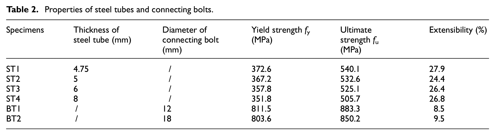
Moreover, follow the Chinese standard GB/T 228-2010. 32 Twelve tensile coupon tests (three coupon tests to each thickness) were conducted to obtain the material characteristics of the steel tubes. In addition, six bolt tensile parts were tested. The average values of measured yield strength, ultimate strength and extensibility of steel tubes and connecting bolts were presented in Table 2, in which ST1–ST4 represent steel tube materials and BT1–BT2 represent bolt materials.
Properties of steel tubes and connecting bolts.
Test setup
A 500-tones electro-hydraulic servo pressure test machine was employed to carry out the axial compression experiments in the structural testing laboratory of Anhui Polytechnic University, and the loading device was shown in Figure 4. In order to ensure the concentric loading condition, the centroids of the pedestal, the specimen and the steel loading block were located on the same line. And the program with set loading rate controls the real-time load generated by the actuator to act on the specimen through the loading plate, and the equipment base is the source of the reaction force at the bottom of the specimen. It was difficult to install adequate strain gages to capture all these random buckling deformations. Thus, after considering the excellent symmetry of the circular section, 10 measuring points, consisting of 6 on the steel tubes surface and 4 in the middle of the bolts, were arranged as shown in the Figure 5 to measure their hoop and axial strain. L1, L2, L3, and L4 in Figure 5 correspond to the data in Table 1. And the data measured at odd-numbered measuring points are circumferential strain, while the data measured at even-numbered measuring points are longitudinal strain.
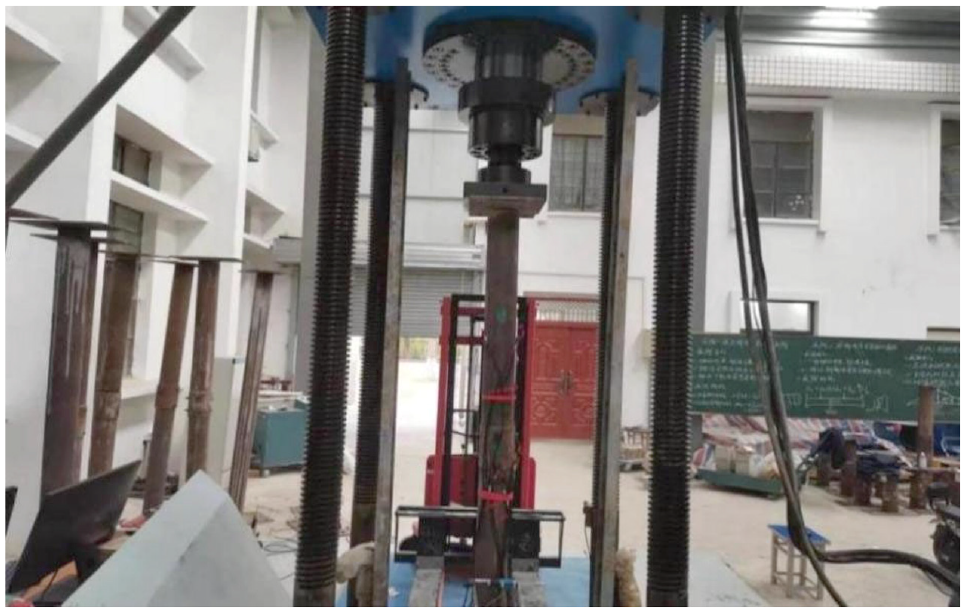
500-tones electro-hydraulic servo pressure test machine.

Test arrangements: location of strain gages and LVDTs: (a) three-dimensional diagram and (b) two-dimensional diagram.
And the LVDT displacement sensors were arranged as shown in Figure 5 to measure the vertical and lateral displacement changes of the specimen. Numbers 1–12 in the figure refer to strain gages on steel tubes, while numbers 13–20 refer to bolts. Especially, considering that the lateral displacement of the short column is small or even may not exist, the lateral displacement meter were given enough initial displacement to prevent the short column from bending in the opposite direction. The specimens were loaded by controlling the vertical loads and displacements of the pressure plate of electro-hydraulic servo pressure testing machine. Under the rate of 6 kN/min, the load was applied until the load reaches 200 kN, which changed to the rate of 0.15 mm/min, and when the load dropped to 85% of the ultimate load or the deformation of the specimen was large, the loading was stopped.
Experimental results and discussion
Failure mode
Continuous CFST column
All the specimens experienced a similar failure process in the early stage of loading, only the residual cement mortar on the steel tube gradually peeled off. And the local buckling of DBCS1–DBCS3 with the same length only near the top and bottom of steel tube, as shown in Figure 6. DBCS1–DBCS3 were subjected to shear failure, which is manifested by two obvious local buckling and a clear shear failure line on the steel tube. The failure mode of DBCS4 was an S-shaped bending, accompanied by local buckling in the mid-height region.
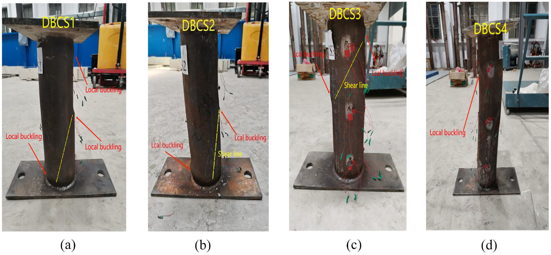
The failure mode of DBCS1–DBCS4: (a) DBCS1, (b) DBCS2, (c) DBCS3, and (d) DBCS4.
PCSCFST column connected by weld and bolt combination
We can see that the lower steel tube of PCSCFST13 had no obvious deformation, and the closer the upper steel tube was to the weld joint, the more serious the deformation was, and the two bolts were also cut off, which caused one side of the outer steel tube to slide down, as shown in Figure 7. This phenomenon reflects that the improvement of failure mode of PCSCFST column by welding connection may be far weaker than that of bolt connection.

The failure mode of PCSCFST13.
PCSCFST column
The failure modes of PCSCFST1–PCSCFST4PCSCFST6–PCSCFST7 with the specimen length of about 490 mm were very similar as shown in Figure 8(a) to (d) and (f) to (g). Local buckling first appeared in the middle of these PCSCFST short columns, and then obvious annular convex or arc-shaped expansion deformation appeared near the column feet of the upper or lower steel tubes, which is often referred to as “elephant’s foot buckling.” Moreover, the end deformations of the two bolts connecting the upper steel tube and the two bolts connecting the lower steel tube on the outer steel tube were respectively warped toward the top and bottom of the steel tube. Therefore, we can deduce that the upper and lower bolts bend in the direction of acting force and reaction force respectively. The upper steel tube of PCSCFST5 was severely deformed while the lower steel tube was basically not deformed, as shown in Figure 8(e). Moreover, PCSCFST5 had no bolt warping and no local buckling in the middle of outer steel tube, which was different from other short columns with a length of 490 mm. Only the part of the upper steel tube that was not wrapped by the outer steel tube of the whole specimen had local buckling. And that part looked more like an independent short column individual with elephant’s foot buckling. This may be due to the semi-continuity of the specimen itself and too thick outer steel tube, which hindered the continuous development of deformation. The main failure mode of the long columns PCSCFST8–PCSCFST12 with a length greater than 490 mm was bending in the middle area, as shown in Figure 8(h) to (l). In addition, PCSCFST8–PCSCFST11 outer steel tube has local buckling in the middle region, while PCSCFST8 upper and lower column feet have arc-shaped local buckling. Meanwhile, the PCSCFST12 had the initial eccentricity caused by bending due to the error of the actual size of the outer steel tube of PCSCFST 12 compared with the design size. This may have aggravated the bending of PCSCFST12, which caused the bolts to be sheared. Furthermore, the deformation of PCSCFST10–PCSCFST12 was mainly the bending in the middle of the specimen, and the local buckling was too small to be observed clearly.
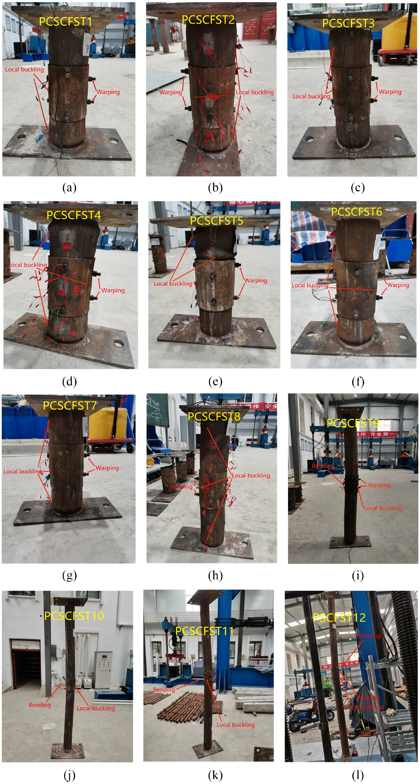
The failure mode of PCSCFST1–PCSCFST12: (a) PCSCFST1, (b) PCSCFST2, (c) PCSCFST3, (d) PCSCFST4, (e) PCSCFST5, (f) PCSCFST6, (g) PCSCFST7, (h) PCSCFST8, (i) PCSCFST9, (j) PCSCFST10, (k) PCSCFST11, and (l) PCSCFST12.
Adding bolts had obvious effects on the failure mode. This is because the bolt has the function of resisting shear, so that there was no obvious shear failure of PCSCFST. Furthermore, under the condition of ensuring the consistency of steel tube thickness at all positions, PCSCFST column is more beneficial to engineering application than CFST column because of its more regular local buckling. Thus, the performance of PCSCFST column in failure mode is better than that of continuous CFST column as control group. And the performance of pure bolted PCSCFST column is better than that of continuous CFST column, which can also be clearly seen by comparing the failure modes.
Axial load (N)-axial displacement (Δ) curves
Continuous CFST column
The bearing capacity and stiffness of continuous CFST columns were gradually enhanced with the increase of core concrete strength, as shown in Figure 9. Meanwhile, this favorable influence on PCSCFST column and continuous CFST column was greatly reduced after the concrete strength increases beyond C40. On the contrary, the increase of the length of the specimen produces the opposite result, that is, the bearing capacity was obviously reduced.

The axial load-axial displacement curve of DBCS1–DBCS4.
Comparison of three types of CFST columns
Figure 10 shows the axial load-axial displacement relationship of three different CFST columns. From Figure 10(a) to (d), we can see that the bearing capacity and stiffness of PCSCFST were enhanced with the increase of core concrete strength, which was similar to that of continuous CFST columns; nevertheless, with the increase of the strength of the core concrete, the increasing range of the bearing capacity after the elastic stage was not as obvious as the stiffness. Compared with the PCSCFST columns, the continuous CFST columns have curves with a much deeper slope in the initial stage of loading, but after that, the curve of PSCFS columns are obviously larger than that of continuous CFST columns. Thus, it can be concluded that PCSCFST columns had a much smaller stiffness in the initial stage of loading, but a higher load carrying capacity and a better deformation resistance at the later stage. The ultimate load of the specimens is defined as the maximum applied load during loading. However, no matter whether it was PCSCFST column or continuous CFST column, the bearing capacity of specimens with length less than 1470 mm did not decrease during loading. Compared with DBCS1, PCSCFST13 had a worse stiffness, but a better bearing capacity after the elastic stage, as shown in Figure 10(e). Thus, the conclusion that the performance of bolted connection was superior to that of welded connection can be drawn.
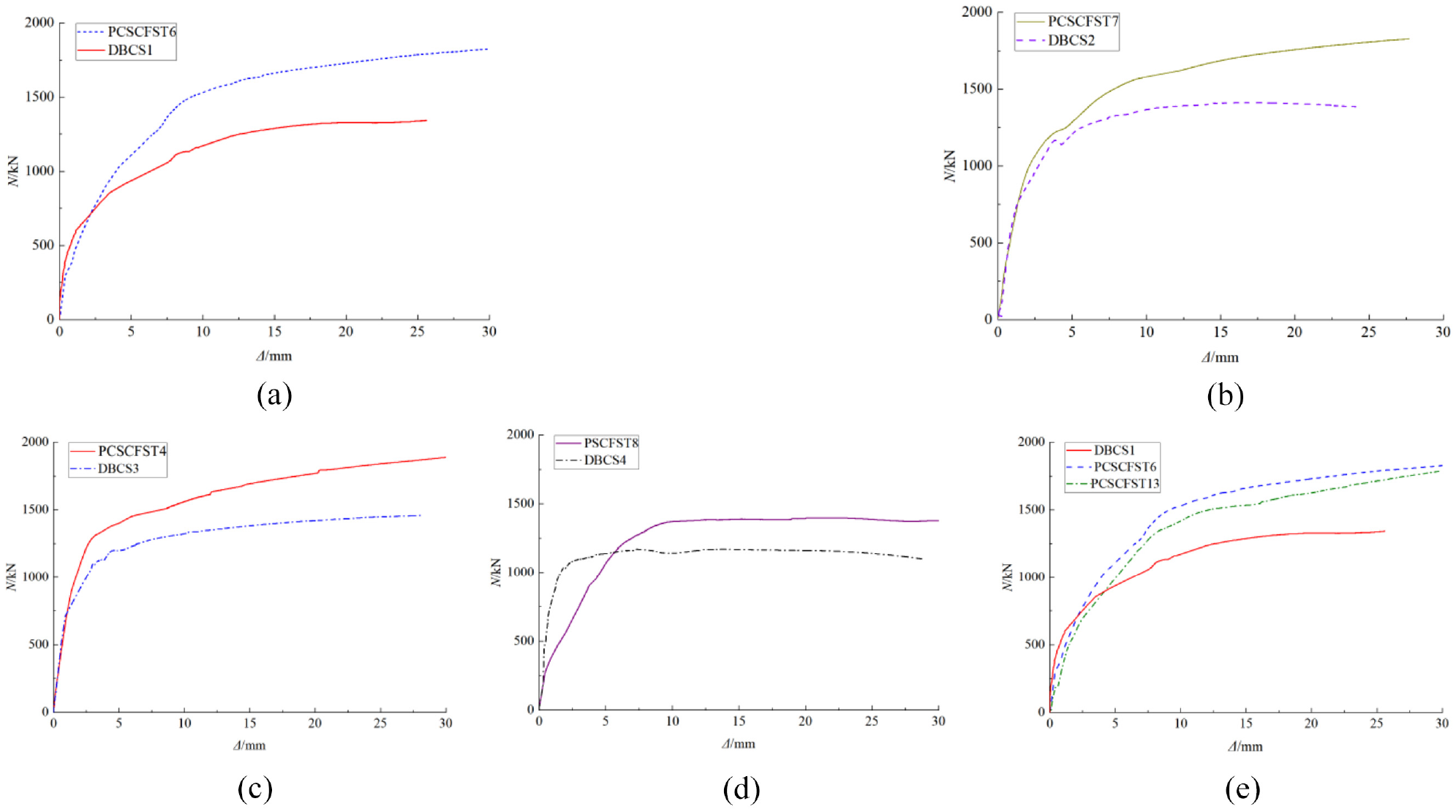
The axial load-axial displacement curve of three types of CFST columns: (a) 30 MPa concrete strength, (b) 40 MPa concrete strength, (c) 50 MPa concrete strength, (d) 770 mm specimen length, and (e) connection method.
Parameter analysis of PCSCFST column
Figure 11 shows the influence of each parameter on the axial load-displacement relationship of the specimen. From Figure 11(a), we can see that the bearing capacity and stiffness of PCSCFST were enhanced with the increase of core concrete strength. The bearing capacity and stiffness of PCSCFST column increased with the increase of the thickness of outer steel tube, as shown in Figure 11(b). We can see the PCSCFST3 have a larger stiffness in the elastic stage, but a worse bearing capacity at the later stage. Similarly, we can deduce from Figure 11(b) that increasing the thickness of the upper and lower steel tubes can also enhance the bearing capacity and deformation resistance of the specimen. Moreover, it can be concluded that when the thickness of steel tubes was not exactly the same as that of outer steel tube, the short board effect occurred. Thus, to improve the bearing capacity and material utilization of the specimens, a higher consistency between steel tubs thickness and outer steel tube thickness, is recommended. From Figure 11(c), we can easily know PCSCFST10 have a larger bear capacity, but a worse deformation resistance after the axial pressure reached 93% ultimate load. In addition, the increase in bolt diameter from 12 to 18 mm resulted in a reduction in ultimate load of approximately 6.5%. The increase of bolt diameter by 50% made the specimen have a worse compressive bearing capacity but a better shear capacity after the failure stage. So excessive increase of bolt diameter not only reduced the bearing capacity of the specimen, but also the deformation resistance. This may be due to the excessive increase of the bolt diameter, which led to the excessive reduction of the area of concrete that shared the main bearing capacity in the section area. And what Figure 11(d) shows is the bearing capacity and stiffness of PCSCFST columns were enhanced with the increase of their length, and the curve has a descending stage after slenderness ratios (λ = 4L/D, where L and D are the calculated length and diameter of the column respectively) of specimens reached 42. As the length of the specimen increased from 1470 to 2454 mm, the ultimate load decreased by approximately 13.3%. For columns with large slenderness ratio, the larger the initial eccentric moment caused by various accidental factors, the larger the additional bending moment and the corresponding lateral deflection, which increased the eccentric moment of the load. With the increase of the load, this interaction caused the columns to be destroyed in advance and dropped the compressive load of long columns. In addition, under the long-term load, the creep of concrete further increased the lateral deflection of the column, which led to the further decrease of the bearing capacity of the long column. It was the turn of PCSCFST12, and the ultimate load was greatly reduced, as shown on Figure 11(d). As the length of the specimen increased from 2454 to 3260 mm, the ultimate load decreased by approximately 77.9%. Particularly, PCSCFST12 had to stop loading because of manufacturing errors that caused it to bend abnormally in the later stage of loading. From the above data, we can draw the conclusion that the greater the slenderness ratio increased, the more severe the compressive bearing capacity of the member decreased.
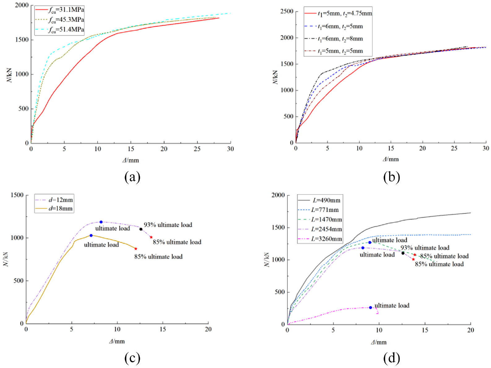
The axial load-axial displacement curves with different parameters: (a) concrete strength, (b) thickness of steel tube, (c) diameter of bolt, and (d) length of specimen.
Axial load-lateral deflection curves
The measured lateral displacement of the short column is very small and the local buckling of the steel tube is dominant, which proves the conjecture before the test. Thus, PCSCFST10 with complete lateral deflection record and load drop stage was selected as a typical example for analysis. Figure 12 shows the curve of axial load and transverse deflection along the height of the PCSCFST column. Lateral deflection developed slowly until the load reaches 85% Nu. When Nu was reached, lateral deflection became severe. The influence of the second moment resulted the lateral deflection increased rapidly after the load reached Nu. 33 PCSCFST10 was found to bend at about three fifths of the height, which led to the asymmetry of lateral deflection here. Anyway, we can still see that the lateral deflection at each loading level was approximately semi-sinusoidal in shape.

The axial load-lateral deflection curve of PCSCFST10.
Load-strain curves of steel tubes
The load-strain curves are illustrated in the following figures to display the effect of core concrete strength, thickness of steel tubes and outer steel tube, length of specimens, diameter of bolts, and connection method, respectively. In graph, the left part illustrates the relationship between the axial load and the axial strain, and the right part represents the relationship between the axial load and the hoop strain. The axial and hoop strains shown in the figure are typical measuring points selected after measuring with resistance strain gages. The deformation in the failure mode can prove that the strains did reach the yield strain even though what some of the following figures show is not, which was caused by the breaking of the connecting line of the strain gage during the experiment. Particularly, on the basis of considering the symmetry of the specimen, measuring points 5 and 6, 9 and 10, 15 and 16, 17 and 18 were selected as the typical measuring points for steel tubes, outer steel tubes and bolts, respectively. The monotonic ascending state of the curve and the existence of bilinear relationship are similar to the strain phenomenon in the article of Tang et al. 34 This phenomenon shows that the core concrete of PCSCFST column and CFST column was strongly constrained by the steel tubes.
Continuous CFST column
The increasing of the core concrete strength of continuous CFST columns had little effect on the hoop strain, but a negative effect on the axial strain before the steel tube yielded, which tends to be stable with the increasing of the concrete strength, as shown in Figure 13. This may be because the core concrete mainly provides the bearing capacity of members rather than resisting deformation. Combined with the phenomenon in failure mode, it can be seen that the measuring points of DBCS4 were not at the bending deformation.

The axial load-strain curves of steel continuous CFST columns.
Comparison of three types of CFST columns
What Figure 14 shows is the anti-deformation advantage of PCSCFST column compared with continuous CFST column was not clear in the elastic stage, but obvious after the steel tube yielded. From the phenomenon in Figure 15(a) that the slope of the curve of the combination connection of bolt and weld is much more obvious than that of the pure bolt connection, the conclusion that the bolt connection can greatly improve the deformation resistance of the specimen can be deduced. It can be observed from the figure that the strain of the outer steel tube near the weld is significantly larger than that of the steel tube.
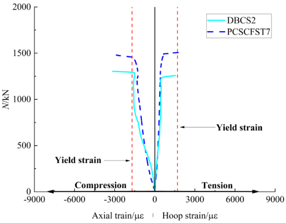
The axial load-strain curves of steel tubes.
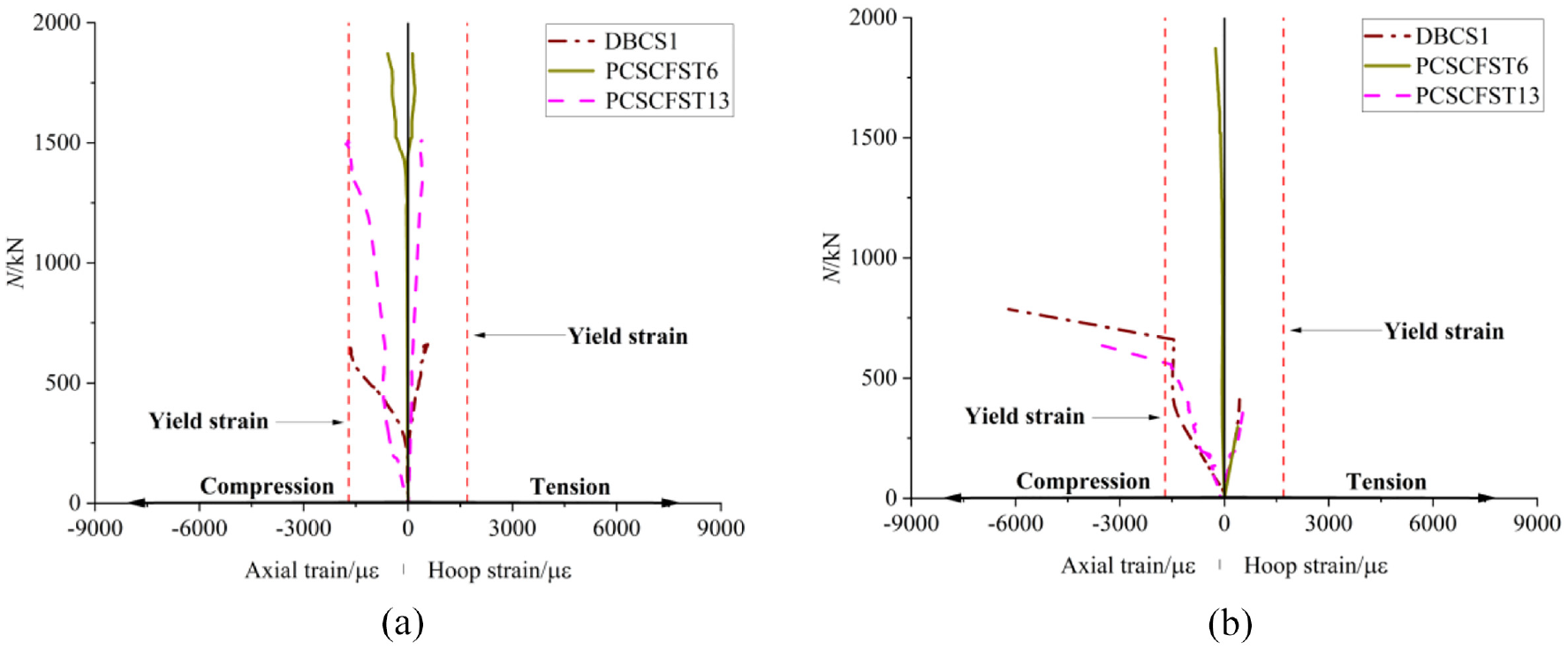
The axial load-strain curves of different types CFST columns: (a) points 5 and 6 and (b) points 9 and 10.
Parameter analysis of PCSCFST column
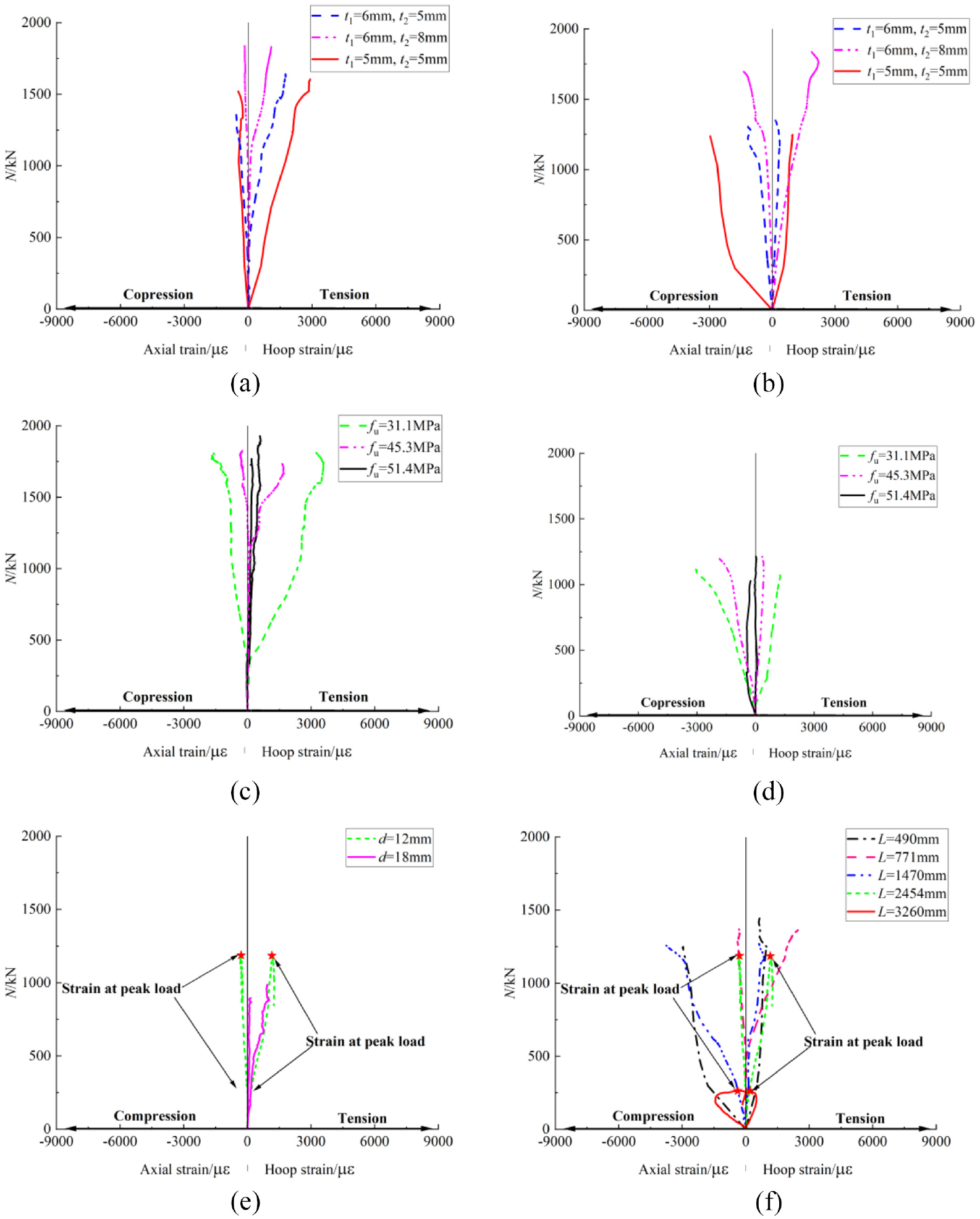
With the improvement of concrete strength, the strain curve of PCSCFST column changes similar to that of continuous CFST column, as shown in Figure 16(a). Figure 16(b) and (c) shows that the smaller the thickness of steel tube and outer steel tube, the larger the curve slope and strain, which proved that the increase of the thickness of steel tube and outer steel tube improved the load-carrying capacity and ductility of the specimens, which was attributed to the enhanced external constraints of the core concrete. The conclusion that the consistency of the thickness of the steel tube and the outer steel tube can significantly enhance the deformation resistance of the specimen can be drawn. The reverse extension of strain curve in different situations after peak load can be observed in Figure 16(d), which reflects the expansion of core concrete after crushing. The phenomenon that the slope and height are different and the influence of bolt diameter change on strain is mainly manifested in the outer steel tube area can also be observed. Thus, a 50% increase in bolt diameter resulted not only in a reduction in bearing capacity but also lightly in ductility and anti-deformation ability can be concluded. The slope of the strain curve of the outer steel tube of the specimen with the length of 770 –2454 mm is positively correlated with the length, as shown in Figure 16(g). Meanwhile, Figure 16(f) and (g) show that the strain change of steel tubes is not much obvious when the bolt diameter and specimen length change, but the strain curve of the outer steel tube shows obvious changes correspondingly. This indicates that instability may lead to the deformation of PCSCFST columns with slenderness ratio greater than 70 under axial compression, mainly bending in the middle region, and local buckling also concentrated in the outer steel tube. It should be noted that PCSCFST12 has obvious initial eccentricity before axial loading due to manufacturing errors, which makes its strain change not accord with the above conclusions.

The axial load-strain curves of steel tubes with different parameters: (a) points 5 and 6 with concrete strength, (b) points 5 and 6 with thickness of steel tube, (c) points 9 and 10 with thickness of outer steel tube, (d) points 5 and 6 with diameter of bolt, (e) points 9 and 10 with diameter of bolt, (f) points 5 and 6 with length of specimen, and (g) points 9 and 10 with length of specimen.
Load-strain curves of bolts
Figure 17 shows the influence of various parameters on bolt strain. From Figure 17, it can be seen that the strain curves of the upper and lower bolts connecting the upper and lower steel tubes on the outer steel tube show an approximately axisymmetric phenomenon, which is mutually verified with the previous failure mode. Figure 17(a) and (b) shows that the ductility can be enhanced by increasing the thickness of steel tube. When the thickness of the outer steel tube is increased to a large difference from that of the steel tube, the specimen has a larger strain. Considering the strain of steel tubes comprehensively, the strain of steel tubes decreased and the strain enhancement of internal bolts, which was caused by the fact that the thickness of outer steel tube is greater than that of upper and lower steel tubes, which weakened the internal force shared by buckling of steel tubes and aggravated the internal force shared by bolts. Thus, in order to better develop the deformation resistance of components in engineering applications, to keep the thickness of upper and lower steel tubes and outer steel tube highly consistent is recommended. Figure 17(c) show that the strain of bolts is hierarchical, but its magnitude and growth rate decrease with the increase of concrete strength, which may be caused by the arrangement of the strain gage of the outer steel tube just in the discontinuous area of the core concrete. The smaller the strength of concrete, the smaller the value and variation range of strain can be observed from the figure. Considering the strain of steel tubes comprehensively, the strain increase of inner bolts and the strain decrease of steel tubes were due to the increase of core concrete strength, which intensified the internal force shared by bolts and weakens the internal force shared by steel tube buckling. Increasing the bolt diameter by 50% is not conducive to ultimate bearing capacity, while beneficial to improving ductility, as shown in Figure 17(e). Excluding the influence of initial eccentricity and local buckling at the measuring point, Figure 17(f) shows that the strain decreases with the increase of specimen length. Therefore, to appropriately increase the bolt diameter in engineering application is recommended. The increase of the length aggravated the instability of the specimen, which resulted in the internal force borne by some core concrete being shared by the steel tube, which can lead to the conclusion that the force borne by the bolt becomes smaller. And the strain gage was damaged shortly after the experiment began, which led to the bolt strain of the specimen connected by weld and bolt combination could not be obtained. However, the conclusion that the deformation of the bolt in the connection mode of pure bolt connection was better than that in the connection mode of bolt and weld joint can still be summarized by means of failure mode.
The axial load-strain curves of bolts with different parameters: (a) points 15 and 16 with thickness of steel tube, (b) points 17 and 18 with thickness of steel tube, (c) points 15 and 16 with concrete strength, (d) points 17 and 18 with concrete strength, (e) points 15 and 16 with diameter of bolt, and (f) points 17 and 18 with length of specimen.
Prediction of axial load-bearing capacity
To the best of the authors’ knowledge, the PCSCFST column in this paper is a new research object whose outer sleeve and bolts are equivalent to constraints on the specimen, that is, it can be regarded as a new derivative form of confined CFST column. Thus, the axial bearing capacity formula of confined CFST columns is used as a reference for the analysis in this chapter.
Confined CFST column
An analytical model, Lai and Ho’s model, 14 was proposed to predict the axial bearing capacity of CFST columns confined by rings. The authors previously proposed to relate σsθ/σsy(where σsθ is the hoop stress in the steel tube under bi-axial state; σsy is the uniaxial yield strength of the steel tube) and n for predicting the axial bearing capacity, which should satisfy the following boundary conditions:
Lower bound: σsθ = 0 and is = σsy (σsz is the axial stress in the steel tube). In this condition, the confinement index ξ is so small (taken as ξ ≤ 1/75) that the induced confinement effect can be ignored. Thus, the steel tube will serve as longitudinal reinforcement only without contributing any confinement effect.
Upper bound: σsθ = σsy and σsz = 0. In this case, the confinement provided is very strong and the specimen will become very ductile (taken as ξ ≥ 6.68). Thus, the steel tube serves as confining reinforcement without contributing any axial resistance. The proposed equations are as follows:

Geometry and hoop stress of the steel tube by considering the free body diagram as shown in Figure 18.


Free body diagram for confining stress (with rings).
Where fcc is the confined concrete stress;
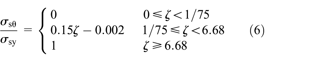
When Von-Mises failure criterion (Equation (1)) was used, the radial stress of steel tube can be neglected.14,35,36 Since there is always friction between concrete and steel tube, the above-mentioned upper boundary conditions can’t be met, Lai and Ho proposed a modified model. Equation (6) was modified to:

Besides modifying formula (7), it was also considered that the axial bearing capacity under 0.1 axial strain may not be feasible in practical design. Therefore, in this model, the strength corresponding to 0.05 axial strain was regarded as the bearing capacity of normal-strength concrete-filled-steel-tube (NSCFST) column, which showed no strength degradation in the post-elastic stage. Equation (8) is the description of the instability reduction factor of the bearing capacity formula of slender columns in Zhu and Liang’s model. 33

where φ is the slender reduction factor for specimens, ul is the effective length of the specimen, Isc is the sectional inertia.
Propose the analytical models of PCSCFST column
The bearing capacity prediction formula of PCSCFST column needs to be revised on the basis of Lai et al. and because of the existence of bolts and semi-continuity. Equation (5) was modified to:


Based on the constraints at both ends of the experimental specimen and the length of component, Equation (10) modified from Zhu and Liang’ s model is used to determine the reduction factor of the specimen.

Where Asc is the area of the PCSCFST section, k1k2 are the correction coefficient of bearing capacity, n’ is the number of bolt, Nbc is the bearing capacity of bolt, d’ is the diameter of bolt,
And the predicted ultimate bearing capacity is compared with the experimental results and listed in Table 3. For the specimen with no descending section of load-displacement curve, the strength corresponding to 25 mm axial displacement was regarded as the bearing capacity of PCSCFST column; with descending section of load-displacement curve, the first peak strength is regarded as the bearing capacity.
Test results and predicted results of PCSCFST columns.

Conclusions
In this paper, an axial compression behavior of PCSCFST columns was presented. A total of 17 specimens were prepared and tested to examine the effect of tube thickness, outer tube thickness, connection method, concrete strength and tube length, including 13 PCSCFST columns and 4 continuous CFST columns. Moreover, a theoretical equation was proposed for predicting the ultimate bearing capacity of PCSCFST based on an analysis of the test results and a reference of typical models. The test results and discussions lead to the following conclusions:
Compared with continuous CFST columns, PCSCFST columns had better bearing capacity, stiffness, and ductility as the existence of bolts and outer steel tube that strengthens the constraint of steel tubes to core concrete.
Maintaining the consistency of the thickness of each steel tube on the specimen can not only improve the local buckling, but also avoid the short plate effect to give full play to the material performance.
On the premise that the thickness of each steel tube is relatively consistent, the increase of steel tube thickness enhanced the confining pressure of PCSCFST column and thus, the axial compression performance was improved.
The improvement of bearing capacity and stiffness with the increase of concrete strength was more obvious than the enhancement of anti-deformation ability as the main function of core concrete is to bear the pressure.
Pure bolt connection can improve the axial compression performance of PCSCFST column more than weld joint and bolt combination connection. Meanwhile, the existence of bolts led to the failure mode of PCSCFST column not including obvious shear failure as continuous CFST column. However, the increase of bolt diameter from 12 to 18 mm resulted in a better strength degradation rate, but worse bearing capacity and deformation resistance.
The increase of slenderness ratio aggravated the degradation of axial compression performance of PCSCFST column, which was the same as that of continuous CFST columns.
With the increase of steel tube thickness, concrete strength, bolt diameter, reduction of member length, and pure bolt connection instead of bolt and weld combination connection, the deformation resistance of bolts had been enhanced.
Based on all the test results and three analytical models taking into account the confining and slenderness ratio effects, as well as the consideration of bolts, a formula for estimating the axial bearing capacity of PCSCFST column is proposed. It is seen that the modified model proposed by the authors give the best prediction of axial bearing capacity of the PCSCFST columns.
Footnotes
Handling Editor: Chenhui Liang
Declaration of conflicting interests
The author(s) declared no potential conflicts of interest with respect to the research, authorship, and/or publication of this article.
Funding
The author(s) disclosed receipt of the following financial support for the research, authorship, and/or publication of this article: This study is funded by Colleges and Universities in Anhui Province Project under Grant No.KJ2020A0366 and KJ2021A0504 and KJ2018A0118, Anhui Natural Science Fund Project under Grant No.1708085QE121, National Natural Science Fund Pre-project of Anhui Polytechnic University under Grant No. 2019yyzr08, National Innovation and Entrepreneurship Training Program Project for College Students under Grant Nos. 202010363123 and 202110363122, Anhui Polytechnic University Research Project under Grant Nos. Xjky2020173 and Xjky2020170 and Xjky110201912.