
Abstract
Many loads on engineering structures had obvious randomness, such as earthquakes, wind, sea waves, uneven pavement, etc. The calculation and analysis of random vibration were complicated and inefficient, which has perplexed the development of engineering technology for a long time. To solve the above problems, this paper proposed a harmonic equivalent excitation method for structural random vibration analysis. The excitation force of multi-frequency action in continuous time interval was converted into harmonic excitation force with the same effect as superposition excitation in each discrete time interval by a harmonic equivalent method. The frequency and amplitude of harmonic excitation force in discrete-time intervals were calculated, which were then taken as the deterministic load input of the structure. The response of the structure was calculated by the conventional structural dynamic analysis method. Finally, the harmonic equivalent excitation method was used to analyze random pavement excitation and its application in the control of time-delay vibration reduction. The results show that the harmonic equivalent excitation method simplifies the calculation form of random vibration analysis without reducing the accuracy, and provides an effective method for analyzing random vibration in the engineering field.
Introduction
Marked by Einstein’s study of Brown motion in 1905, random vibration has entered the scope of academic research. As a technical discipline with a wide range of engineering backgrounds, random vibration was generally believed to have been discussed for more than half a century since an academic conference on the application of random vibration was held at Massachusetts Institute of Technology in 1958. Its importance was also increasingly recognized by academia and engineering circles. However, their application in the engineering field was greatly limited because the traditional calculation and analysis methods were too complicated.1–4
Random vibration of vehicles produced by defects in roads and tracks, and its efficient management, have become major concerns in the design of vehicle safety, comfort, and durability in recent years, with the fast expansion of car and train to high speeds.5,6 When the structural system was quite complex, the calculation and analysis of random vibration were complex and inefficient, which has puzzled the development of engineering technology for a long time. Taking vibration reduction of dynamic vibration absorber as an example, Olgac and Hosek7,8 first proposed the concept of absorbing the vibration energy of the main system by using a time-delay feedback control structure based on the displacement of the vibration absorber mass and achieved a notable effect. In order to further verify the damping effect of time-delay control and design the dual-frequency time-delay dynamic vibration absorber that can completely suppress the vibration of the main system under fixed dual frequency.9,10 Chen and Cai11,12 studied the time-delay active control of the rotating motion of the flexible beam and the harmonic excitation force. The numerical simulation and experimental verification show that the time-delay H ∞ control can effectively suppress the elastic vibration of the plate. Zhao and Xu 13 studied the damping performance of nonlinear dynamic vibration absorbers with time delay under single frequency excitation for the main system by using multi-scale method. Through numerical simulation, it was verified that the time-delay dynamic vibration absorber has a good vibration reduction effect on the main system. Alhazz et al. 14 successfully applied the time-delay vibration reduction control mechanism to the vibration reduction of cantilever beams and achieved ideal vibration reduction effect. Although great achievements have been made in time-delay vibration reduction control, the above researches only focused on the main system subjected to a single frequency excitation force, and under such circumstances, the time-delay dynamic vibration absorber has an excellent control system for the vibration response of the main system. However, when the system was subjected to random excitation, the frequency of the excitation force was constantly changing, and the fixed-value time-delay feedback control force cannot effectively control the real-time change of the excitation force frequency. 15 In order to overcome the defect that the traditional passive vibration absorber had a small damping frequency domain and can only obtain effective damping control for specific frequency excitation, finding an active control force that can effectively improve the damping performance of dynamic vibration absorber under random excitation had always been the main research direction of vibration active control technology.
Aiming at the problems brought by random vibration analysis, this paper proposes a harmonic equivalent excitation method of random excitation, which converted multiple simultaneous excitation forces in continuous time intervals into harmonic excitation forces with the same effect as superposition excitation in each discrete time interval. Then the frequency of harmonic excitation force in discrete time interval was calculated, that is, the harmonic excitation corresponding to each assumed frequency was superimposed together as equivalent excitation. Then, the dynamic response of the structure under this deterministic load excitation was calculated. Obviously, the response can be regarded as the superposition of the corresponding responses when each harmonic excitation was assumed to act alone. Finally, the generality and convenience in practical application of the harmonic equivalent excitation method were analyzed through pavement excitation and taking a two-degree-of-freedom vibration absorber as an example.
Principle of harmonic equivalent excitation method
Taking a linear system subjected to a single-point stationary random excitation

In the formula, the transfer function structured by

According to the definition of transfer function

If a harmonic equivalent random excitation

The method of harmonic equivalent excitation was applied to analyze the stochastic dynamic response of the structure. The time-domain range

To calculate the response of the structure under harmonic equivalent excitation, there were:
Analysis of random pavement excitation based on harmonic equivalent excitation method
The excitation of uneven pavement made the vehicle vibrate during driving, thus affecting its ride comfort. Since the 1970s, a large number of scholars have begun to conduct a large number of researches on the random process of pavement roughness.17–19 To undertake vibration analysis, platform experiment, pavement damage prediction, and interactive vehicle-road dynamics, it was essential to construct a time domain model of pavement irregularity as the excitation to automobiles. In this paper, a road roughness time domain model is constructed by filtering white noise method based on random road standardization, 20 and simulated and verified road excitation through the harmonic excitation equivalent method proposed in this paper.
Pavement roughness power density
Random road roughness power spectrum. The longitudinal profile curve of the road (roughness function) 21 refers to the change of the height of the road relative to the datum planeness along the road strike length, as in Figure 1.

Pavement longitudinal section curve.
Generally, the excitation of road roughness is a random process, and the statistical characteristics of the road surface can be expressed by its power spectral density:

Where
ϑ——Frequency index, indicating the slope of the diagonal line on the double logarithmic coordinate, which determines the frequency structure of the road roughness. The low and high frequency bands correspond to different frequency indexes. Under normal road conditions, the frequency index of the graded road surface spectrum is ϑ = 2. Table 1 specifies the upper and lower limits and geometric mean of the road roughness coefficient
Classification standard of road roughness.

Considering the influence of vehicle speed
From equations (1) and (2), the relationship between the power spectral density

The pavement speed power spectral density
Filtered white noise generation method
The basic idea of the filtered white noise generation method was to abstract the random disturbance of road roughness into white noise satisfying certain conditions, and then perform appropriate transformation by the filter to fit the output into a random process with specified spectral characteristics. Filtered white noise road simulation generation method had the advantages of small computation, fast speed and high simulation accuracy. 22 In the simulation process, the “white noise” in the road speed power spectral density expressed by formula (3) was converted into colored noise, thus obtaining the state equation of road roughness in time domain as follows

where
Select the vehicle speed

Harmonic equivalent excitation diagram of Class A pavement: (a) 10S harmonic equivalent excitation diagram of class A pavement, (b) 1S harmonic equivalent excitation diagram of class A pavement, (c) Harmonic equivalent excitation diagram of amplitude of grade A road, and (d) lg value of harmonic equivalent excitation frequency of grade A pavement.
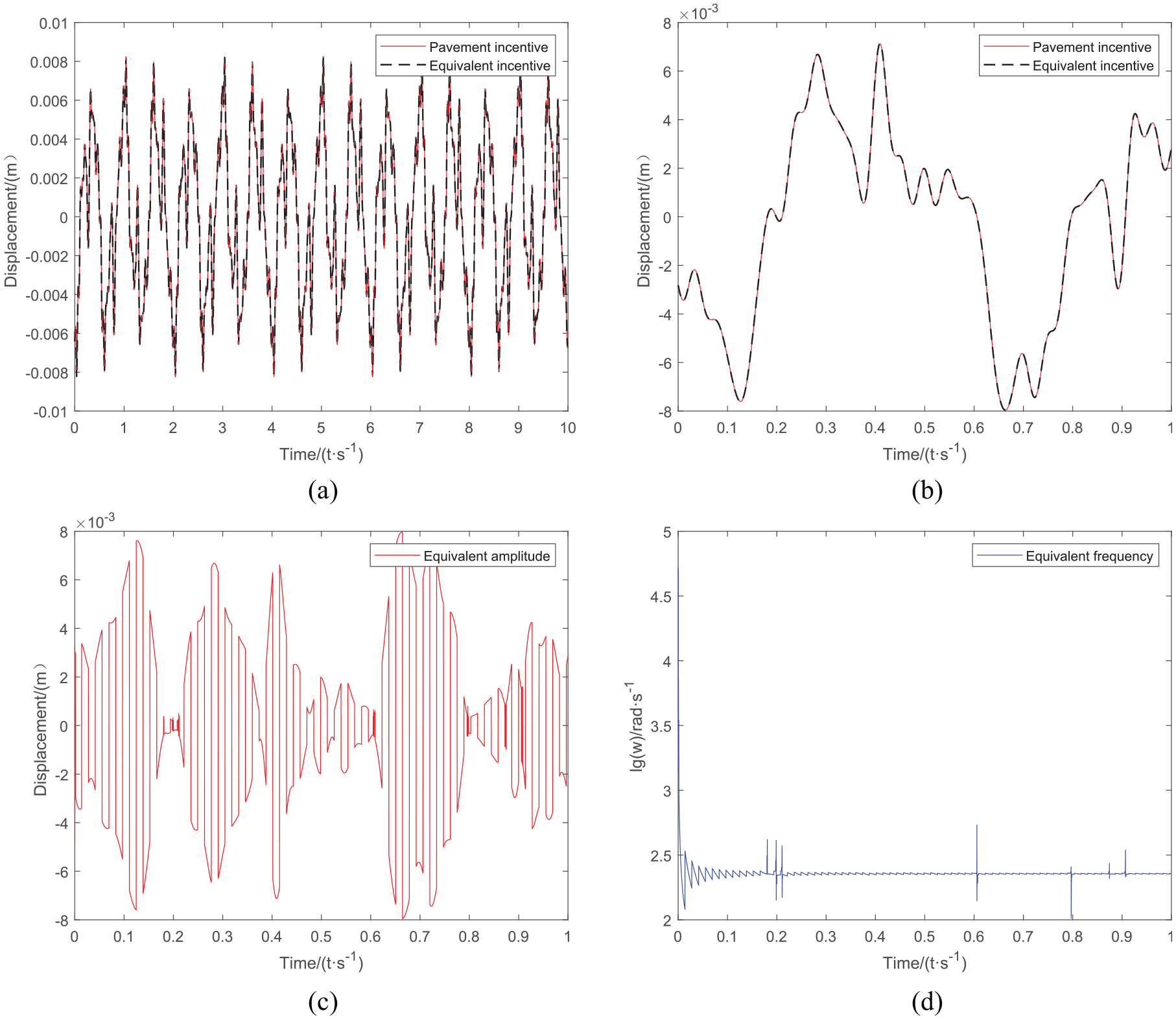
Harmonic equivalent excitation diagram of Class B pavement: (a) 10S harmonic equivalent excitation diagram of class B pavement, (b) 1S harmonic equivalent excitation diagram of class B pavement, (c) Harmonic equivalent excitation diagram of amplitude of grade B road, and (d) lg value of harmonic equivalent excitation frequency of grade B pavement.

Harmonic equivalent excitation diagram of Class C pavement: (a) 10S harmonic equivalent excitation diagram of class C pavement, (b) 1S harmonic equivalent excitation diagram of class C pavement, (c) Harmonic equivalent excitation diagram of amplitude of grade C road, and (d) lg value of harmonic equivalent excitation frequency of grade C pavement.
The harmonic equivalent excitation diagram of Class A pavement was obtained by simulation (as shown in Figure 2). From Figure 2(a) and (b), it was concluded that the harmonic equivalent excitation in each step size can completely simulate the Class A pavement excitation. From Figure 2(c) and (d), it can be seen that that equivalent amplitude
Application of harmonic equivalent excitation method in time-delay vibration reduction control
The use of the harmonic equivalent excitation technique in vibration reduction control was studied using the 2-DOF vibration model of a time-delay dynamic vibration absorber in this section. Previous studies have shown that the time-delay vibration absorber had good vibration reduction control effect for harmonic excitation with single frequency, and the vibration of the main system can be almost completely attenuated. However, the control effect of multi-frequency random excitation was not obvious. In this section, through the proposed harmonic equivalent excitation method, the harmonic equivalent frequency and amplitude were calculated in the discrete interval, and the multi-frequency analysis was divided into single-frequency analysis in the discrete interval. The vibration absorber’s control time-delay settings were then calculated by examining the system’s critical stability in the discrete time interval under equivalent harmonic excitation. 23
Establishment of 2-DOF vibration model
The system dynamics equation of the model is

Where ma is the absorber’s mass, ka is the absorber’s stiffness coefficient, and ca is the absorber’s damping coefficient; xa represents the vibration displacement of the absorber, x represents the vibration displacement of the main system, and xd represents the external displacement excitation; m represents the mass of the main system, k represents the stiffness coefficient of the main system, and c represents the damping coefficient of the main system.

2-DOF vibration system with time-delay dynamic vibration absorber.
Critical stability parameters of time-delay dynamic absorbers
When the external excitation is 0, the dynamic equation of the time-delay dynamic absorber is:

Laplace transform is performed on equation (12), and its characteristic equation is obtained as:

The characteristic equation (13) states that the transcendental equation has an unlimited number of roots, each of which corresponds to a time delay gain g, and the numerical connection is as follows:

The real component of the characteristic root s is denoted by a.
The angle connection is satisfied by the answer of characteristic equation (2):


From equation (15), the progressive direction of the characteristic root locus of the equation is:
When

When

According to engineering control theory,
24
if the system characteristic equation root is located on the left side of the imaginary axis of the complex plane, namely

Where
The Laplace transform of the system dynamic equation (11) can be obtained as follows

Where

The frequency response functions of the vibration displacement of the absorber and the vibration displacement of the main system are respectively given by equations (18) and (19).


Allow for a 0.01 sin external excitation (10t). The critical time-delay parameters of the time-delay dynamic absorber are
As in Figure 6, the frequency response of the main system tends to zero at

(a) Time-delay dynamic absorber frequency response function curve and (b) main system frequency response function curve.

(a) the absorber’s vibration displacement and (b) the main system’s vibration displacement.
Simulation results show that the time-delay control parameters obtained by equations (16) and (17) can effectively control the vibration of the main system.
Harmonic equivalent excitation method for random excitation
It was demonstrated that the time-delay dynamic vibration absorber’s dampening effect was effective for harmonic excitation. The variable harmonic excitation was utilized to replace the random excitation equivalently once the random excitation was known, and the time-delay control parameters corresponding to the harmonic excitation’s equivalent frequency were found in a short time period. Then, in a continuous time period, the time-delay dynamic vibration absorber demonstrated a time-varying time-delay control.
The random excitation was equivalent to the harmonic excitation in the discrete time interval when the random excitation was known, and the continuous time interval was divided into short time intervals, with the harmonic excitation being used to approximate the random excitation in each short interval when the random excitation was known. The harmonic equivalent excitation may entirely approach the original random excitation when the time division was fine enough, and the amplitudes of the two excitations were the same at each discrete time point in the continuous time interval.
In this paper, random excitation was constructed by the method in Su and Tang.
25
Let the equivalent excitation time interval of harmonic excitation be

The harmonic equivalent excitation and the actual excitation equivalent diagram (a) 0–20 s simulation diagram and (b) 0–1 s simulation diagram.
Figure 8 shows how the harmonic equivalent excitation created using the above approach closely resembles the actual random excitation. Figures 9 and 10 show the equivalent amplitude
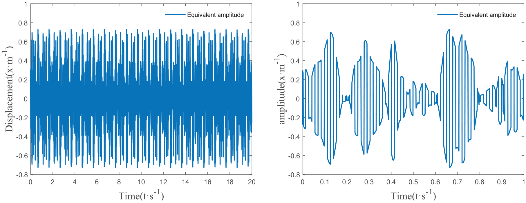
Equivalent amplitude.
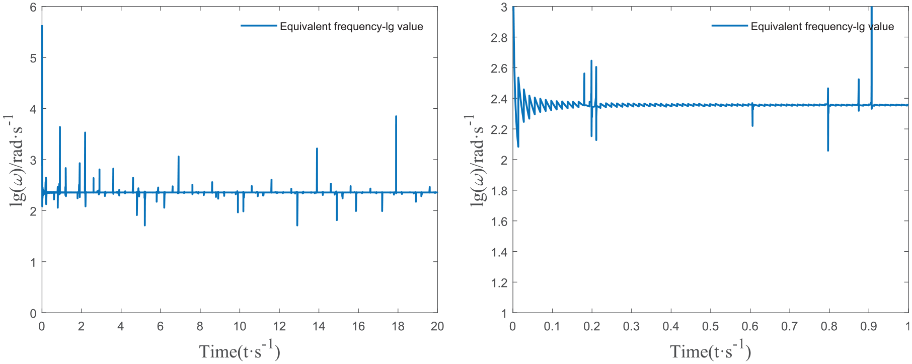
Equivalent frequency.
Time-varying feedback control parameters
According to the critical time-delay solution method, the critical time-delay control parameter

Time-varying time delay.
This paper opted to regulate the vibration absorber with time-varying, time-delay, and constant gain in order to decrease energy consumption during control as much as feasible. To get an adequate fixed time-delay gain g, the foregoing time variation and time delay operated on the time-delay dynamic vibration absorber. The optimization variable was chosen as the time-delay gain g, and the optimization objective function was chosen as the weighted root mean square (WRMS) of each time domain response of the main system. As a result, the modified particle swarm optimization technique was used to optimize and solve the delay gain. 26
The exact integration approach
27
was utilized to solve the 2-DOF vibration system in Figure 5. The time domain response of the vibration system at each time point within

Let the optimization objective function be

where

Flow chart of the optimization process (as in Figure 12)

Flow chart of improved particle swarm method.
The algorithm flow is as follows:
Step 1: Firstly, n pairs of delay control parameters (τn, gn) are randomly selected and denoted as:
Step 2: Calculate the numerical solution of the system dynamics equation (11) under the action of each pair of time-delay control parameters (τn, gn), and obtain the time-domain response of the system. According to the objective function (23), calculate the value of the corresponding evaluation index J, and use array for storage, denoted as:

Where m is the number of groups where the objective function is located, and n is the position of the objective function in each group.
Step 3: Compare the evaluation indexes J1 to Jn one by one in the group, select the time-delay control parameters τ and g corresponding to the minimum evaluation index as the optimal values of the control parameters τp1 and gp1 in this group, and record the smallest evaluation index Jmin in the group as Jp1. When calculating the first group, the global optimal evaluation index Jg is equal to the optimal evaluation index Jp1 in the group, and the global optimal values τg and gg are equal to the optimal values in the group τp1 and gp1.
Step 4: After obtaining the optimal time-delay control parameters in the first group, update the time-delay control parameters, and the update rules are as follows

Where m is the number of groups of the updated control parameters, and n is the position of the control parameters in each group. τpm−1 and gpm−1 are the optimal control parameter values within the group m-1, and τg and gg are the global optimal values. The parameters in the formula are selected as: w = 0.6, a1 = 1.2, a2 = 2.2, r1 and r2 are random numbers uniformly distributed between 0 and 1. Because it is meaningful only when the time lag τ > 0, the absolute value sign is added to the update formula of the time delay

Step 5: Then carry out the second round of calculation when m = 2, according to the method for solving the system dynamics equation and the method for calculating the objective function in the first round, the objective function obtained from the second group of calculations is stored as

The minimum objective function in the second group can be obtained as the optimal time-delay control parameters corresponding to Jpm, denoted as τpm and gpm.
Step 6: Compare the minimum evaluation index Jpm of the m = 2 group with the global minimum evaluation index Jg. If the minimum evaluation index in the group is less than the global minimum evaluation index (Jpm<Jg), the optimal control parameter in the group is used as the global minimum evaluation index. The optimal control parameters (τg = τpm, gg=gpm) if the minimum evaluation index in the group is not less than the global minimum evaluation index (Jpm≥Jg), the global optimal control parameters remain unchanged (τg = τg, gg = gg).
Step 7: When the stopping condition is satisfied (usually the preset operation precision or the number of iterations), the search ends. Then output the result. Otherwise, you need to return to step 3.
Simulation results
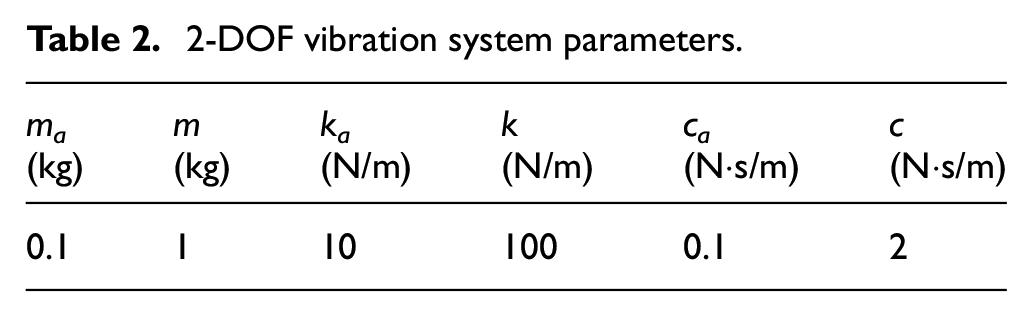
According to the vibration system parameters in Table 2 and the time-varying delay feedback gain control parameters shown in Figure 11, it is brought into the dynamic equation (11) to simulate the vibration response of the main system in time domain. The vibration response of the main system under the action of time-varying delay control strategy and passive control strategy is analyzed. According to 20 s simulation data as in Table 3, for random excitation, the time-varying parameter time-delay dynamic vibration absorber achieved better vibration reduction control effect than the fixed parameter one. Under the control of the fixed parameter delay vibration absorber, the RMS value of the vibration displacement of the main system was reduced from 0.0470 to 0.0355, and the vibration reduction efficiency was 24.53%%. The RMS value of the vibration speed of the main system was reduced from 0.4503 to 0.3348, and the vibration reduction efficiency was 25.65%. The RMS value of the vibration acceleration of the main system was reduced from 0.2147 to 0.1882, and the vibration reduction efficiency was 13.45%. Under the control of the time-varying parameter and time-delay vibration absorber, the RMS value of the vibration displacement of the main system was reduced from 0.0470 to 0.0308, and the vibration reduction efficiency was 34.58%. The RMS value of the vibration speed of the main system was reduced from 0.4503 to 0.3006, and the vibration reduction efficiency was 33.25%. The RMS value of the vibration acceleration of the main system was reduced from 0.2147 to 0.1690, and the vibration reduction efficiency was 22.26%. The simulation results showed that the dynamic absorber with time variation and time delay obtained by equivalent intermittent excitation method was better than the absorber with fixed time delay on damping effect of the main system under random excitation with the effect reaching about 30%. The harmonic equivalent excitation method was used to transform the complex multi-frequency problem into a single-frequency problem in discrete time for random excitation, resulting in the time-delay control parameters of the time-delay dynamic vibration absorber appearing as time-varying time-delay fixed gain parameters in the continuous time interval, reducing the difficulty of time-varying time-delay analysis.
2-DOF vibration system parameters.
Evaluation index root mean square value.

Conclusions
This paper proposes a harmonic equivalent excitation method for random vibration analysis. The following conclusions are obtained through the harmonic equivalent excitation of pavement excitation and its application in time-delay vibration reduction control.
Through the harmonic equivalence of pavement excitation, it is shown that the performance of harmonic equivalent excitation is the same as that of random excitation in discrete time interval. At the same time, the corresponding frequency and amplitude of each time point can be obtained, and the total response of the structure under multi-frequency excitation can be calculated, thus overcoming the difficulties faced by random vibration analysis.
The harmonic equivalent excitation method is introduced to make the time-delay gain adjustment range of the time-delay dynamic vibration absorber wider, and better control parameters can be obtained by using the optimization algorithm, which has more obvious effect than the vibration absorber with fixed time-delay parameters.
Using the equivalent method of intermittent excitation, the vibration response of the system can be accurately calculated from the vibration analysis of harmonic excitation only by constructing a suitable harmonic equivalent excitation according to random excitation.
Footnotes
Handling Editor: Chenhui Liang
Declaration of conflicting interests
The author(s) declared no potential conflicts of interest with respect to the research, authorship, and/or publication of this article.
Funding
The author(s) disclosed receipt of the following financial support for the research, authorship, and/or publication of this article: This work is supported by National Natural Science Foundation of China (Grant No. 51275280).