
Abstract
In order to accurately understand the internal loading state of the single-row tapered roller bearings doubly supporting the main shaft of wind turbine, a 5-DOF mechanical model of such bearing combination in wind turbine was established which considered the axial preload, bearing ring tilt, and roller crown. The positions of the points on the bearing raceways were described mathematically in the Cartesian coordinate system, and the mathematical relationship between the roller-raceway contact deformations and the bearing ring displacements was derived. The effect of bearing ring tilt caused by external loads on the contact load distributions along rollers was considered by dividing the rollers into laminae. The contact stress distribution between roller and raceway was obtained by iterative calculation of the finite length line contact model. The RMSE of the roller load distributions of the upwind bearing and the downwind bearing is 2.25 kN and 3.02 kN respectively. The obtained smallest size necessary for the roller laminae is 1.25% of the roller length. The bearing ring tilt will cause uneven contact load distribution along the roller, and modification of the roller profile improves the load and stress distribution. The machining error leads to the unbalanced contact stress distribution along the roller.
Introduction
Energy shortage and environmental pollution have become the focus of attention in the world. Wind power generation is an important way to develop and utilize clean, environmental, and renewable new energy. In recent years, wind power equipment technology has developed rapidly, 1 and wind turbines are developing toward large-scale models. Bearings are the key load carrying components of wind turbine.2,3 Due to the difficulty of lifting and maintenance of wind turbine, it is very demanding on the reliability of the bearings over a 20 year time span of lifetime. The researches on the related technology of the wind turbine bearings are receiving more and more attention. At present, most researches are aimed at judging the working state of wind turbine bearings for reasonable operation and maintenance arrangement, such as condition monitoring,4,5 fault extraction,6–8 fault diagnosis,9–11 fault prediction, 12 life prediction, 13 health assessment, 14 temperature prediction, 15 etc. The research on mechanics analysis of wind turbine bearings mainly focuses on the pitch bearing or the yaw bearing. Aguirrebeitia et al. 16 established the acceptance load surface of four-contact-point ball bearing which is used in the pitch system or the yaw system of the wind turbine, and the acceptance load surface can be applied for the initial selection of the pitch bearings or the yaw bearings. Zhang et al. 17 established the mechanical models of a four-contact-point ball bearing which is used in the wind turbine with rigid ring and flexible ring assumption respectively. The flexible ring was described by elastic deformation theory of thin-walled ring. The raceway contact forces were calculated for both rigid ring and flexible ring bearing model respectively. Plaza et al. 18 presented a superelement-based finite element model of a four-contact-point ball bearing considering the particular geometries and operational conditions in the pitch system of the wind turbine, the use of superelements significantly reduced the computational cost of finite element model. Shang et al. 19 built a finite element model of a four-contact-point ball bearing and the surrounding structure in the yaw system of the wind turbine by substituting the rolling elements with nonlinear compression springs, which considered the effect of the elasticity deformation of the surrounding structure. Chen and Wen 20 performed finite element analysis of the four-point contact ball bearing in the pitch system of the wind turbine, the traction springs were used to model the rolling elements, the hub and blade were also included in the model. Leupold et al. 21 established a flexible multi-body simulation model of a wind turbine for calculating the rolling element load distribution of the pitch bearing. The hub, bearing ring, and blade were modeled in FEM for considering the flexibility of the bearing rings and the surrounding structural components.
In the existing wind turbines of different types, there are various types of bearing structures supporting the main shaft system. 22 For wind turbines with power above 4 MW, single-supporting double-row tapered roller bearings and double-supporting single-row tapered roller bearings have become the major support forms of direct-drive, hybrid, and doubly-fed wind turbine main shaft systems. For the single-supporting double-row tapered roller bearing form, one double-row tapered roller bearing is used to support the main shaft. 23 For the double-supporting single-row tapered roller bearing, two single-row tapered roller bearings with different size are mounted back to back to support the main shaft together. Compared with single-supporting double-row tapered roller bearing, double-supporting single-row tapered roller bearings not only have advantages in carrying performance, but also can maintain the stability of generator air gap within a certain range through axial preload.
The double-supporting single-row tapered roller bearing of the wind turbine main shaft system is shown in Figure 1. The outer ring of the bearing is mounted in the stator shell of the generator, and the inner ring of the bearing is mounted on the main shaft of the generator. The main shaft is connected to the hub, and the inner ring of the bearing rotates with the main shaft. This kind of support structure can flexibly adopt two bearings with different sizes to meet the needs of loads carrying. The upwind bearing sustains a larger load, so the structure size is larger than the downwind bearing.
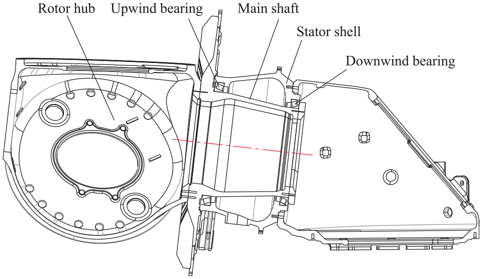
Wind turbine main shaft system.
The load carrying mechanism of tapered roller bearing is complex, and there are many factors affecting the carrying performance. In recent years, scholars have carried out relative research work on tapered roller bearings from different perspectives. Yang et al. 24 proposed a quasi-static equilibrium model for double-row tapered roller bearing in the presence of combined external loads and angular misalignment. The resisting moment, contact loads, and fatigue life of double-row tapered roller bearing under different loads were analyzed, the effect of roller crown on the roller forces was not consider in their work. Tong and Hong 25 investigated the effect of angular misalignment between inner and outer rings on the stiffness characteristics of tapered roller bearing by solving a statics model. The natural frequency behaviors with the stiffness variation due to angular misalignment were also studied by using a dynamic model of a spindle supported by tapered roller bearings. Their model can be used to estimate the characteristics of the bearing. Kabus et al. 26 presented a frictionless quasi-static time-domain model of a tapered roller bearing. The model uses elastic half-space theory to simulate the contact pressures and allows for an arbitrary stiffness of the outer ring supporting structure. Their model considers the bearing misalignments and structural deflections in detailed fatigue life calculation. Zheng et al. 27 presented a quasi-static model of a double-row tapered roller bearing used to support the main shaft of an offshore floating wind turbine for analyzing the fatigue life under oscillating external load and speed conditions. Numerical simulations were carried out to investigate the effects of the oscillating load and speed, angular misalignment, and internal clearance on the fatigue life of the bearing. Duan et al. 28 developed a coupled model by incorporating a quasi-static model of tapered roller bearing and an elastohydrodynamic lubrication model for investigating the roller load distribution and evaluating the lubrication state of roller raceway contact. The effects of crown drop on azimuthal roller load distribution, film thickness, and pressure distribution in the contact area were investigated. Verma and Tiwari 29 proposed an optimum design method of tapered roller bearing for maximum dynamic capacity and minimum variation in dynamic capacity due to variation in basic dimensions. A nonlinear constrained optimization problem with single objective function, 30 realistic constraints and 11 design variables were established. The variation of dynamic capacity with respect to all basic design variables was calculated. Tong and Hong 30 optimized the profile parameters of the partially crowned roller of tapered roller bearing by taking the fatigue life and stiffness as objective. A statics model which is feasible for both aligned and misaligned bearings was used to evaluate the stiffness and fatigue life of the tapered roller bearing. The optimal central flat length and crown radius of the roller profile were obtained by a dimensionless curve-fitting formula. Liu et al. 31 proposed a dynamic simulation method for a tapered roller bearing with a localized surface fault on the rib of the inner race, and the non-Hertzian contact of tapered roller to raceway and rib was considered. The time-varying deflection excitation caused by the fault was formulated by the method. Wu et al. 32 established a multi-body contact dynamic model of tapered roller bearing for considering the dynamic contact relationship among the cage, rollers, and raceways. The impacts of load, grease rheological properties and temperature on the roller tilt, roller skew and bearing slip were simulated by solving the model. Deng et al. 33 established the dynamic differential equations of tapered roller bearing for analyzing the roller dynamic characteristics and cage whirling considering roller tilt and skew. Fine integral method and predict correct Adams-Bashforth-Moulton multi-step method were used to solve the dynamic differential equations of the tapered roller bearing.
Till now, the analysis for single-row tapered roller bearing or double-row tapered roller bearing can be found in the literature, while the analysis for the combination of two single-row tapered roller bearings with different size by one model has not been found yet. The existing research work mainly focuses on the mechanical analysis of a single tapered roller bearing and fails to fully consider the influence factors such as axial preload, bearing ring tilt, and the roller crown on the internal load distribution of two bearings simultaneously. In this study, a calculation method of the internal load distribution by a 5-DOF mechanical model was searched for the combination of two single-row tapered roller bearings which doubly supports the main shaft of wind turbine. The influence factors such as the axial preload, the ring tilt, and the roller crown were included in the method, and the key factors effecting the internal load distribution were analyzed. The rollers were divided into laminae to consider the influence of the bearing ring tilt on the contact load distribution along the rollers. The contact stress distribution in the whole contact region between roller and raceway was calculated iteratively by using finite length line contact model. The main contributions of this paper are summarized as following:
A 5-DOF (Fx, Fy, Fz, My, Mz) mechanical model was proposed for the combination of two single-row tapered roller bearings which doubly supports the main shaft of wind turbine.
The geometric description method for two single-row tapered roller bearings with different size was established. The analysis for the two bearings by one model was proposed for the first time.
The sensitivity analysis of the laminae thickness of the roller on the contact stress distribution was performed, and the smallest size necessary for the laminae was obtained.
The sensitive factors affecting the contact stress distribution between the roller and the raceway of single-row tapered roller bearing were discovered.
The remainder of the paper is organized as follows. Section “Geometric description of bearings” derives the geometric description of two single-row tapered roller bearings in a Cartesian coordinate system. The relationship between the external loads and the displacement of bearing rings is established in section “Load-displacement relationship of bearing rings”. The static equilibrium equations of the two bearings are established in section “Equations of static equilibrium”. The calculation method of contact stress between roller and raceway were derived in section “Contact stress between roller and raceway”. Analysis and discussion of a case is performed in section “Analysis and discussion”. Conclusions and findings are given in section “Conclusion”.
Geometric description of bearings
The main bearings of the wind turbine are used to withstand the loads from the wind wheel and the gravity of the main shaft. These loads act in the load coordinate system at the hub center. In order to facilitate the description of the geometric relationship inside the bearings, a Cartesian

Coordinate system of bearing combination.
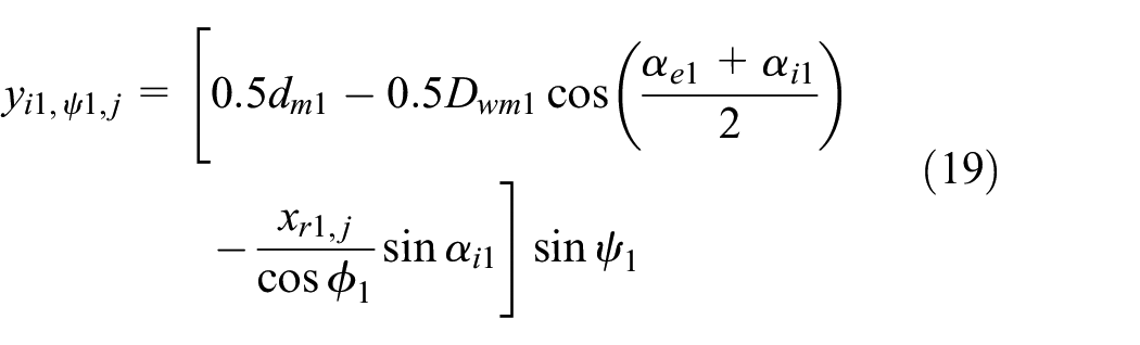
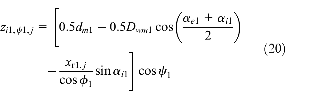
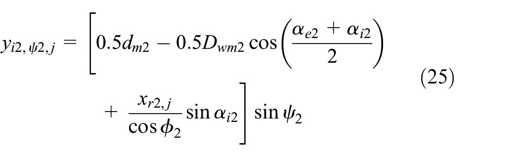
Coordinates of roller-raceway contact line midpoint
Under the action of external loads, line contact between the roller and raceway will occur. The two sets of bearings have four raceways, and the midpoint of the raceway contact line is denoted by
At roller location azimuth

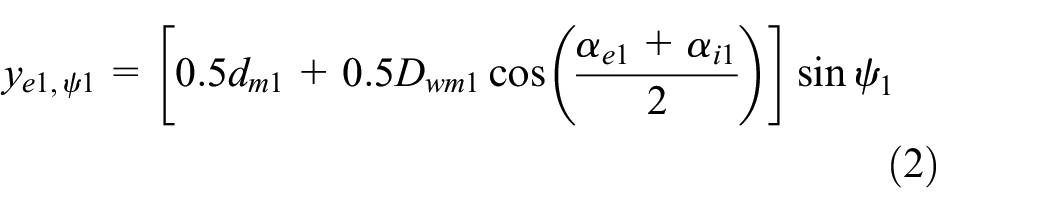

where
The coordinates of the contact line midpoint


At roller location azimuth


where
The coordinates of the contact line midpoint


Coordinates of roller lamina-raceway contact point
In order to consider the influence of ring tilt and roller crown on the contact load distribution of roller, the roller was divided into laminae along the axial direction. In the bearing axial plane where the roller axis is located, a two-dimensional coordinate system
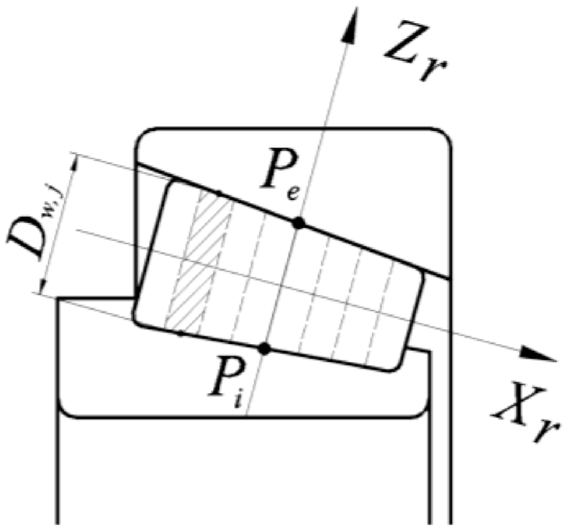
Coordinate system of roller.
According to the relationship in Figure 3, the coordinate of the thickness center of each roller lamina in the

where
The roller diameter at the central position of the thickness of each roller lamina can be expressed as:

where
In combination with the geometric relationship in Figures 2 and 3, the coordinate expression of the contact line midpoint between the roller lamina and the raceway can be obtained. At roller location azimuth


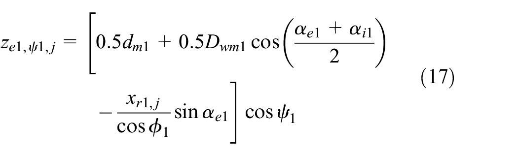
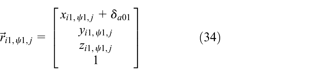
The coordinates of the contact line midpoint between the roller lamina

At roller location azimuth


The coordinates of the contact line midpoint between the roller lamina


Load-displacement relationship of bearing rings
Under the action of external loads, contact deformation occurs between the rollers and raceways inside the two bearings, thus causing the displacement of the bearing rings. It is assumed that all rollers are evenly distributed on the circumference of the bearing, and the location azimuth of each roller remains unchanged before and after the bearing being loaded.
Displacement of bearing rings under preload
In order to maintain the stability of the generator air gap, the rigidity of the main shaft need to be improved by the axial preloading of the main shaft bearings. Under the action of axial preload

The contact load between roller and outer raceway is 34 :

where

where
Consider the bearing inner ring and all rollers as an isolation body, it sustains the joint action of axial load

where
From equations (27) to (30) above, the displacement of the inner ring of the upwind bearing along the
Similarly, the displacement of the inner ring of the downwind bearing along the

where
Displacement of bearing rings under external loads
In order to calculate the position of the point on the raceway contact line after the bearings being loaded by external loads, the coordinates of the point on the contact line are expressed in vector form as following equations (33)–(36):


The outer rings of the two bearings are mounted in the fixed stator shell of the generator and remain stationary . Under the action of the external load

After the displacements of the main shaft and the bearing inner rings being generated, the vector


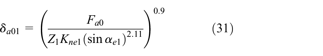
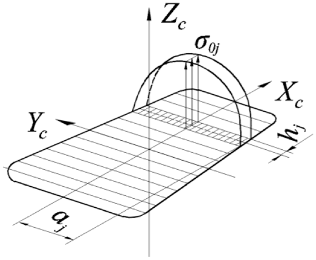
Profile crowning of the rollers is necessary for avoiding the stress concentration at the roller ends. Lundberg 36 firstly proposed a crowning shape defined by a logarithmic function. Lundberg’s equation has the drawback that the profile curve is not continuous at the ends. Stress concentration cannot be completely avoided as bearing ring tilt occurs. Many researchers try to improve the shortcomings of Lundberg’s methods, 37 such as combining logarithmic curve with circular arcs, introducing more parameters into the logarithmic profile equation. These improved logarithmic equations contain more parameters, which need to be calculated repeatedly till obtaining reasonable values, otherwise, concentrated stress cannot be overcome at the roller ends. These studies only stay at the academic level, which are not convenient for design, implementation, and manufacturing of the roller. In this paper, the profile equation of the roller from ISO/TS 16281:2008 38 was used. This formula has been verified by a lot of practice and recognized by the bearing manufacturer. The profile equation of the roller was defined as 38 :

The elastic contact deformation between the roller lamina

The elastic contact deformation between the roller lamina

At roller location azimuth
At location azimuth

Similarly, the expression of normal contact load
Equations of static equilibrium
The isolation body composed of the bearing inner rings and all rollers is in equilibrium state under the combined action of external load
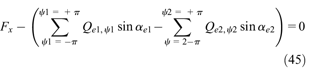


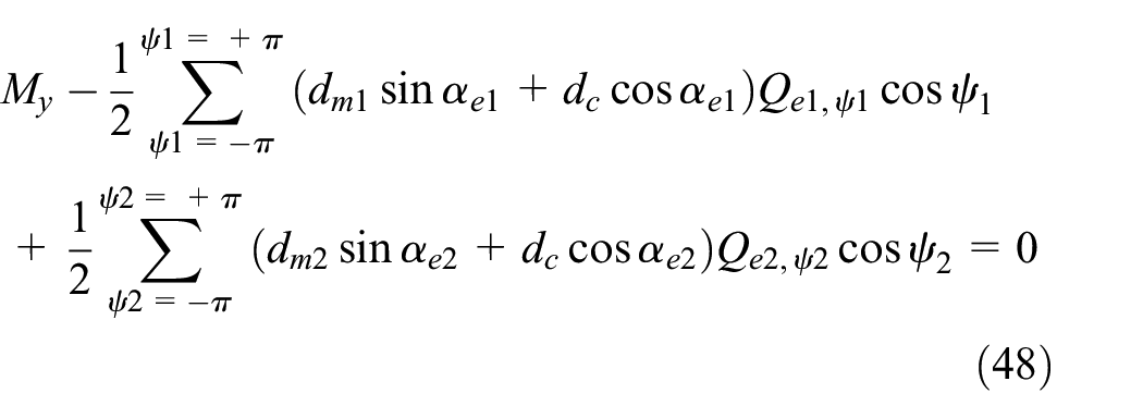

Equations (45)–(49) constitute a system of nonlinear equations with unknown quantities
Contact stress between roller and raceway
The contact between the roller and raceway is a finite length line contact, which belongs to a non-Hertzian contact problem. Suppose that the roller surface and raceway surface are continuous and smooth, and the influence of surface roughness is ignored. The friction between roller and raceway is not considered. In order to calculate the contact stress distribution between the roller and raceway, the contact region coordinate system
Coordinate system of contact region.
According to the finite length line contact theory, the basic equation of contact between two elastic bodies under the action of external force


where,
Considering the tilt of roller generatrix relative to raceway generatrix, equation (51) becomes the following form:

where
The contact region between the roller and raceway is divided into strip elements along the
where
According to equation (53), the normal contact load generated by the element

Define the flexibility coefficient

Equations (54) and (55) were used for discrete processing of equations (50) and (52), so the following can be obtained:


where
Equaitons (56) and (57) constitute the basic equation of the contact mechanics model between the roller and raceway. The parameters
Analysis and discussion
The two single-row tapered roller bearings to be analyzed are used in a 6 MW direct-drive wind turbine. The calculations were performed by the proposed method, and they were also performed by the commercial software Romax for verification purpose. The main design parameters of the bearings are listed in Table 1. The axial span between the width centers of the two bearings is dc = 1500 mm. According to the translation theorem of force, the acting loads at the hub center were translated to the coordinate origin at the bearing span center, and the acting loads at the span center were obtained as follows: Fx = −35.2 kN, Fy = 161.0 kN, Fz=−1738.4 kN, My=−21,315.0 kN m, Mz=−897.5 kN m.
Main parameters of bearings.
Analysis of internal load distribution
Based on the acting loads and design parameters of the bearings, a 5-DOF mechanical model of the bearings was established firstly by using equations (45)–(49), then the solutions were obtained as follows:

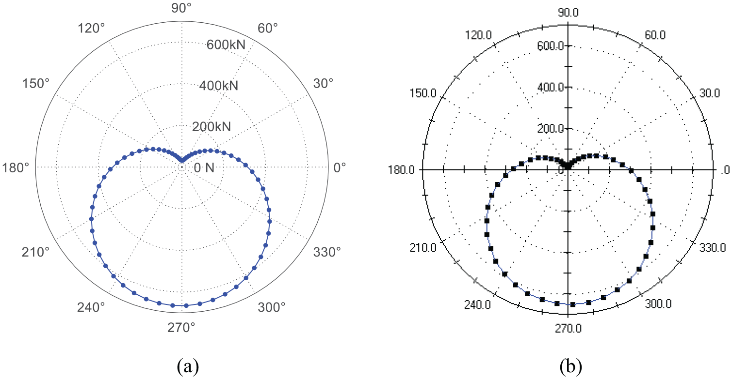
Roller load distribution of upwind bearing: (a) results by proposed method and (b) results by Romax software.
Roller load distribution of downwind bearing: (a) results by proposed method and (b) results by Romax software.
As can be seen from the figure, all rollers of the two bearings are subjected to load, so the bearings are in a tight preloaded state. The RMSE between the roller load distributions of the proposed method and those of Romax were calculated as following, the upwind bearing is 2.25 kN, the downwind bearing is 3.02 kN, the level of these differences is negligible. This shows the correctness of the method in this paper. Figure 7 shows the lamina load distribution of the most heavily loaded roller. The angular displacement of the bearing ring causes the roller to have a slight uneven load distribution along the roller. Because of the modification of roller profile, the lamina load on both ends of roller decreases gradually.

Roller lamina load distribution: (a)upwind bearing and (b) downwind Bearing.
According to the obtained maximum roller load and roller tilting angle, the contact stress distribution between the roller and the inner raceway was calculated by using equations (56) and (57). The sensitivity analysis of the laminae thickness on the contact stress distribution between the roller and the raceway was performed. RMSE change of contact stress distribution curve with the laminae thickness change is shown in Figure 8. Horizontal scale of the figure is the percentage of the laminae thickness to the roller length. As shown in the figures, with the decrease of the laminae thickness, the RMSE curve first drops rapidly and then flattens out. When the laminae thickness percentage drops to 1.25, the RMSE of the upwind bearing is 0.29 MPa, the upwind bearing is 0.40 MPa, the level of these errors is negligible. So the smallest size necessary for the laminae is 1.25% of the roller length.

RMSE of contact stress distribution curve: (a)upwind bearing and (b) downwind Bearing.
The contact stress distribution between the roller and the inner raceway results by the proposed method and Romax are shown in Figures 9 and 10. The RMSE between the contact stress distributions of the proposed method and those of Romax were calculated as following, the upwind bearing is 6.03 MPa, the downwind bearing is 9.57 MPa, the level of these differences is negligible. These shows the correctness of the method in this paper. The contact stress is evenly distributed along the roller generatrix, and there is no stress concentration at both ends of the roller. Figure 11 is the three-dimensional graph of stress distribution in the contact region, and in the width direction of the contact region the stress conforms to Hertzian contact.
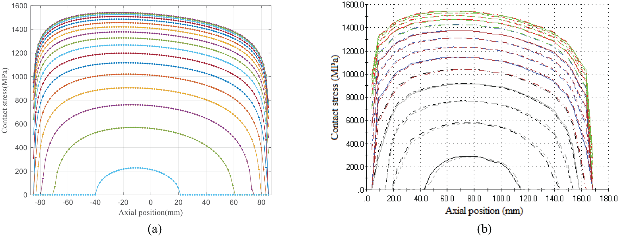
Roller contact stress distribution curve of upwind bearing: (a) results by proposed method and (b) results by Romax software.

Roller contact stress distribution curve of downwind bearing: (a) results by proposed method and (b) results by Romax software.

Roller contact stress 3D distribution: (a) upwind bearing and (b) downwind bearing.
Discussion of machining error on contact stress
The mechanical model established in this paper considers the bearing parts as ideal geometries. There exist certain deviation between each geometric parameter of the actual machined bearing and the theoretical design value, especially for the conical raceway surface and tapered roller surface, the machining and measuring are difficult, so it is difficult to achieve high accuracy. The machining error of the bearing will affect the contact stress distribution inside the bearing, making it deviate from the reasonable distribution of theoretical design. The effect of machining error of the bearing raceway cone angle and tapered roller cone angle on the contact stress of raceway are discussed below.
Effect of outer raceway cone angle error
When the cone angle of the outer raceway has machining error, the cone angle will deviate from the theoretical design value. Figure 12 shows the contact stress distribution curves between the most heavily loaded roller and the outer raceway when the cone angle of the outer raceway deviates from the theoretical design value in both positive and negative directions. As can be seen from the figure, when the outer ring raceway cone angle deviates from the theoretical design value, the contact stress distribution will be biased toward one end of the roller.
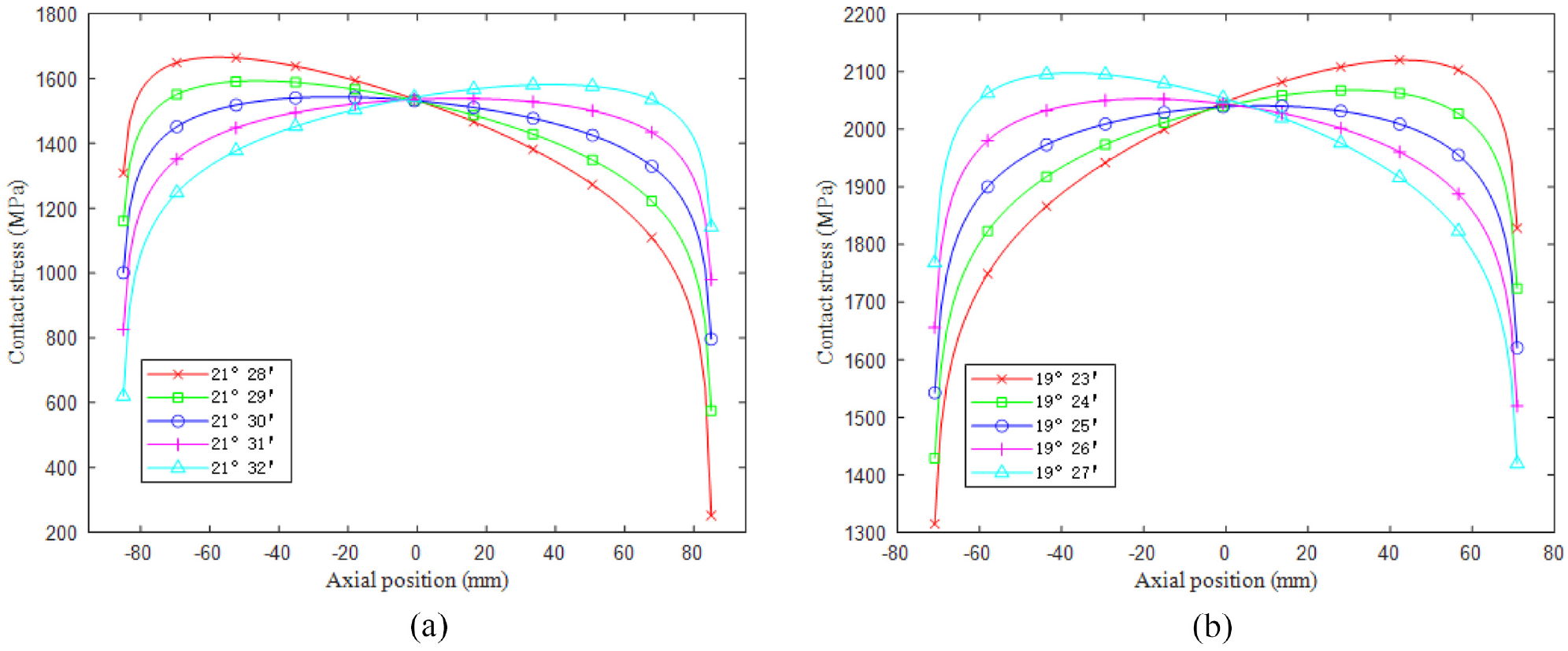
Roller contact stress distribution with variation of outer raceway cone angle: (a) upwind bearing and (b) downwind Bearing.
For the upwind bearing, when the outer raceway cone angle is less than the theoretical design value of 21°30′, the contact stress of the big roller end increases, while the contact stress of the small roller end decreases. When the cone angle is larger than the theoretical design value, the change of roller contact stress distribution is opposite.
For the downwind bearing, when the outer raceway cone angle is less than the theoretical design value of 19°25′, the contact stress of the big roller end decreases, while the contact stress of the small roller end increases. When the cone angle is larger than the theoretical design value, the change of roller contact stress distribution is opposite.
Effect of inner raceway cone angle error
When the cone angle of the inner raceway has machining error, the cone angle will deviate from the theoretical design value. Figure 13 shows the contact stress distribution curves between the most heavily loaded roller and the outer raceway when the cone angle of the inner raceway deviates from the theoretical design value in both positive and negative directions. As can be seen from the figure, when the inner ring raceway cone angle deviates from the theoretical design value, the contact stress distribution will be biased toward one end of the roller.

Roller contact stress distribution with variation of inner raceway cone angle: (a) upwind bearing and (b) downwind bearing.
For the upwind bearing, when the inner raceway cone angle is less than the theoretical design value of 20°10′, the contact stress of the big roller end decreases, while the contact stress of the small roller end increases. When the cone angle is larger than the theoretical design value, the change of roller contact stress distribution is opposite.
For the downwind bearing, when the inner raceway cone angle is less than the theoretical design value of 18°15′, the contact stress of the big roller end increases, while the contact stress of the small roller end decreases. When the cone angle is larger than the theoretical design value, the change of roller contact stress distribution is opposite.
Effect of roller cone angle error
When the cone angle of the roller has machining error, the cone angle will deviate from the theoretical design value. Figure 14 shows the contact stress distribution curves between the most heavily loaded roller and the outer raceway when the cone angle of the roller deviates from the theoretical design value in both positive and negative directions. As can be seen from the figure, when the roller cone angle deviates from the theoretical design value, the contact stress distribution will be biased toward one end of the roller.

Roller contact stress distribution with variation of roller cone angle: (a) upwind bearing and (b) downwind Bearing.
For the upwind bearing, when the roller cone angle is less than the theoretical design value of 40′, the contact stress of the big roller end decreases, while the contact stress of the small roller end increases. When the cone angle is larger than the theoretical design value, the change of roller contact stress distribution is opposite.
For the downwind bearing, when the roller cone angle is less than the theoretical design value of 35′, the contact stress of the big roller end increases, while the contact stress of the small roller end decreases. When the cone angle is larger than the theoretical design value, the change of roller contact stress distribution is opposite.
It can be seen that the contact stress distribution of roller is very sensitive to the cone angle error of raceway and roller of the bearing. The machining error of the cone angle of the raceway and roller will affect whether the roller can be uniformly loaded. The error of cone angle will cause the uneven load of the roller, which will accelerate the fatigue failure of the heavy-duty side of the raceway surface and shorten the life of the bearing.
Conclusion
A 5-DOF mechanical model of single-row tapered roller bearings for doubly supporting the wind turbine main shaft was established, which considered the factors of axial preload, the ring tilt, and the roller crown. The positions of the points on the bearing raceways were described mathematically in the Cartesian coordinate system, and the mathematical relationship between the roller contact deformation and the ring displacements was established through coordinate transformation.
The load distribution of roller inside the bearing was obtained by numerical solution of the model, and the contact stress distribution between roller and raceway was obtained by iterative calculation of the finite length line contact model. The calculated results of the proposed method are completely consistent with those of commercial software Romax, which shows the correctness of the method in this paper. The follow conclusions were obtained:
Based on the acting external loads and design parameters of the bearings, the roller load distributions were calculated by the proposed 5-DOF mechanical model. The RMSE between the roller load distributions of the proposed method and those of Romax were calculated as following, the upwind bearing is 2.25 kN, the downwind bearing is 3.02 kN, the level of these differences is negligible.
The effect of bearing ring tilt caused by external loads on the contact load distributions along rollers was considered by dividing the rollers into laminae. The angular displacement of the main shaft causes the roller to have a slight uneven load distribution. The modification of roller profile makes the lamina load on both ends of roller to decrease gradually.
The stress distribution between roller and raceway in the contact region was obtained by numerical iterative calculation. The stress in the center of the contact width is evenly distributed along the roller generatrix, and the profile modification avoids the stress concentration at both ends of the roller.
The sensitivity analysis of the laminae thickness of the roller on the contact stress distribution was performed. With the decrease of the laminae thickness, the RMSE curve first drops rapidly and then flattens out. The obtained smallest size necessary for the laminae is 1.25% of the roller length.
The machining error of the bearing will affect the distribution of contact stress inside the bearing, making it deviate from the reasonable distribution of theoretical design. When there is cone angle error on the outer raceway, inner raceway, or roller surface, there will be uneven distribution of roller contact stress. The contact stress distribution of roller is very sensitive to the cone angle error of raceway and roller of the bearing.
Footnotes
Appendix
Handling Editor: Chenhui Liang
Declaration of conflicting interests
The author(s) declared no potential conflicts of interest with respect to the research, authorship, and/or publication of this article.
Funding
The author(s) disclosed receipt of the following financial support for the research, authorship, and/or publication of this article: This project was supported by the National Key R&D Program of China (No. 2018YFB0407304) and the Major Science and Technology Project of China National Machinery Industry Corporation (No. SINOMAST-ZDZX-2019-02).
Data availability
The data that support the findings of this study are available from the corresponding author upon reasonable request.