
Abstract
In order to research the lubrication characteristics of various restrictors on the aerostatic bearing, an aerostatic bearing with the multi-hole integrated restrictor (MIR) was proposed in this paper. The gas film flow field at the orifice outlet of the MIR aerostatic bearing was numerically calculated and analyzed by using the numerical calculation method combined with the large eddy simulation and the over-relaxation iteration. The results showed that there was a pressure drop at the orifice outlet and the pressures were separated in the thickness direction of the gas film clearance, and the lubrication performance of the multi-hole integrated restrictor was better than that of the single-orifice restrictor. The fluctuation and micro-vibration of the flow field can be effectively reduced and suppressed by reasonably setting the parameter of the multi-hole integrated restrictor. It was proposed that the region near the orifice outlet of the MIR aerostatic bearing was divided into five regions to analyze and discuss the lubrication characteristics of the flow field, which provided a good means and method for further research the fluctuation and micro-vibration of the flow field at the orifice outlet.
Introduction
Due to their high precision, no friction, no pollution, and long service life, aerostatic bearings have been widely used in the fields of precision manufacturing and measuring equipment. The compressibility of the gas brings great difficulties to improve the stability of the flow field of the aerostatic bearing, so how to enhance the stability of the aerostatic bearing has become difficulties and hot spots.1,2 With the development of precision and ultra-precision manufacturing and measuring equipment for higher precision requirements of motion guide, various factors that were ignored in the past and affected the performance of aerostatic bearings has been gradually considered and concerned.3–5 The micro-vibration of the gas film flow field is closely related to the motion state of the inner gas film of the aerostatic bearing. Therefore, it is the key to research the flow pattern of the gas film formed in the flow field of the aerostatic bearing.
Many scholars have carried out a series of related research on the gas film flow pattern at the orifice outlet of the aerostatic bearing.6,7 Mori researched the pressure distribution of the circular aerostatic bearing with single orifice and found that the pressure near the orifice outlet decreased rapidly and then gradually increased by increasing the gas supply pressure or the gas film clearance of the aerostatic bearing, and it was proposed for the first time that there was a sharp pressure drop in the orifice outlet area. 8 Al-bender proposed to divide the whole flow field of the aerostatic bearing into three regions: the intake region of the orifice based on the adiabatic expansion assumption, the inlet region of the flow field where the pressure drop may produce turbulent impact, and the viscous region which strictly obeyed the Reynolds equation. Among them, the inlet region of the flow field has become the focus of a large number of scholars and paid attention to its pressure drop phenomenon. 9 Mao found in the aerostatic guideway system that even if there was no external interference, the system would produce nano-level vibration, and thought that it was caused by the gas flow, but did not elaborate on the mechanism of micro-vibration. 10 Aoyama et al. 11 observed the cyclone at the orifice outlet and changed the right angle of the junction between the orifice and the gas film clearance of the aerostatic bearing into the filleted corner, which reduced the cyclone intensity and the micro-vibration of the gas film flow field.
Eleshaky 12 researched the circular aerostatic bearing and numerically solved the three-dimensional compressible N-S equation. He found the pressure drop and fluctuation phenomenon of the gas film flow field of the aerostatic bearing and believed that the typical micro-vibration was caused by the interaction between the compression wave and the boundary layer. 12 Zhu et al. 13 studied the transient characteristics of the vortex in the flow field of the aerostatic bearing and focused on the interaction between the vortex shedding and pressure fluctuation in the gas film flow field. Chen et al. 14 proposed a novel design of aerostatic bearings with an arrayed micro-hole restrictor, which had uniformly distributed micron-sized holes in an arrayed pattern such that the total restriction area was the same as that of a single orifice restrictor, and studied the eddy current and micro-vibration characteristics of aerostatic bearings with AMR by CFD analysis software. Chen et al. 15 researched the influence of these parameters on the air vortices and nano-vibration in aerostatic bearing by changing the design parameters and functional parameters, and established the direct relationship between the gas vortices and nano-vibration in aerostatic bearings. Li et al. 16 designed the flow field disturbance structure for the aerostatic thrust bearing with the air chamber to change the microscopic flow field inside the bearing, and the numerical calculation and experimental results showed that the fluctuating pressure of the bearing flow field with the flow field disturbance structure was decreased obviously and the microvibration was suppressed evidently. Chen and He found the cyclone phenomenon at the orifice outlet of the aerostatic bearing, and put forward the viewpoint that the cyclone was the cause of micro-vibration. Whether there was correlation between the cyclone and the micro-vibration or not, it was necessary to research the mechanism of the micro-vibration from the aerodynamic model of the aerostatic bearing, which provided a new idea and direction for solving the problem of the micro-vibration in the gas film flow field of the aerostatic bearing. 17
In the supporting process of aerostatic bearings, a micro-vibration is mainly generated by its internal gas flow, which is different from the self-excited vibration of gas hammer. Its amplitude is only nanometer to submicron and its frequency ranges from tens of Hertz to thousands of Hertz. 18 As the motion and positioning accuracy of the ultra-precision moving platform gradually approaches the submicron or even nanometer level, the amplitude of the micro-vibration of the aerostatic bearing has been close to the accuracy of the moving platform. Therefore, the micro-vibration in the flow field needs to be weakened or eliminated.19–21 Combined with the characteristics of various restrictors, an aerostatic bearing with the multi-hole integrated restrictor (MIR) has been proposed and designed. The large eddy simulation has been used to solve the N-S equation in the region of the flow field at the orifice outlet of the MIR aerostatic bearing, and the over-relaxation iterative method based on the finite difference has been used to numerically calculate the Reynolds equation in other regions of the flow field. The fluctuations and the micro-vibration of the MIR aerostatic bearing have been explored and researched in this paper.
Physical model and control equation
Physical model
An aerostatic bearing is an important basic component supporting precision and ultra-precision motion mechanism. The stability of its gas film flow field is the key factor restricting and affecting the motion accuracy of the mechanism. In the process of moving support, a kind of micro-vibration is mainly produced by the internal gas flow of the aerostatic bearing, which is different from the self-excited vibration of the air hammer, and its amplitude is only nanometer to submicron. The micro-vibration has become the main technical obstacle to improve the stability and quality of aerostatic bearings. Combined with the characteristics of various restrictors, the MIR aerostatic bearing is proposed and designed in this paper. The physical model structure diagram is shown in Figure 1.

The physical model structure diagram of the MIR aerostatic bearing.
In Figure 1, a multi-hole integrated restrictor with the radius of r is arranged at the center of the working surface of the MIR aerostatic bearing, and a central orifice is set at the center of the multi-hole integrated restrictor. Several small orifices with the diameter of 0.05–0.30 mm are uniformly distributed around the central orifice according to certain rules. The type of the multi-hole integrated restrictor is represented by the n × d, where n is the number of the orifice on the multi-hole integrated restrictor (including the central orifice) and d is the diameter of the orifice; such as the 5 × 0.2 means that there are five orifices with the diameter d = 0.20 mm on the multi-hole integrated restrictor, of which there is one orifice in the center of the multi-hole integrated restrictor and four orifices are evenly distributed around it. The geometric parameters of the physical model of the MIR aerostatic bearing are expressed as follows: ϕD is the diameter of the MIR aerostatic bearing, and H is the height of the MIR aerostatic bearing. The internal geometric parameters of the part A of the orifice outlet of the MIR aerostatic bearing shown in Figure 1 are as follows: r is the radius of the multi-hole integrated restrictor; b is the distance between the peripheral orifice and the central orifice on the same multi-hole integrated restrictor; ϕd is the diameter of the orifice; n is the number of the orifice; l is the length of the orifice; h is the gas film clearance; ϕD1 is the diameter of the dotted line selected in the calculation area of the gas film flow field.
Control equation
The fluid motion in the gas film flow field between the MIR aerostatic bearing and the bearing parts of the guide needs to meet the three conservation laws of mass, momentum and energy, including the continuity equation, momentum equation, and energy equation. The N-S formula of its Cartesian tensor expression is equations (1)–(3). 22


Where: ρ is the density of the gas; t is the time; ui and uj are the velocity components of i and j directions in Cartesian coordinates; xi and xj are the coordinates of i and j directions; σij is the element (component) of the viscous stress tensor; the subscript i is the normal direction of the action surface, and the subscript j is the projection direction of the force; E is the total internal energy per unit mass of the fluid; p is the gas film pressure in the flow field; qi is the heat flux in direction i of the gas film flow field in Cartesian coordinates.
The large eddy simulation is used to solve the flow field at the orifice outlet of the MIR aerostatic bearing. The equations (1)–(3) are filtered by density weighting, and the control equations of the large eddy simulation are (4)–(6). The density and the pressure are filtered by physical space and expressed by superscript “∼”; the velocity, the temperature, and the internal energy are filtered by density weighting and expressed by superscript “–”.


In equation (5), two additional terms are generated after filtration, both of which are related to subgrid pulsation. Where
Boundary conditions
Due to the limitation of computational resources and efficiency, the large eddy simulation method is used to solve the governing equations (4)–(6) in the gas film region (the area within the diameter ϕD1 of part A of the dotted box in Figure 1) near the orifice outlet. 23 In other regions (the area outside the diameter ϕD1 of part A of the dotted box in Figure 1), the over relaxation iteration method is used to calculate the simplified Reynolds equation. The dashed box A of the flow field in Figure 1 is selected as the research object, and the three-dimensional modeling diagram of the orifice outlet area is shown in Figure 2. The section of the computational physical model is obtained along the section B-B in Figure 2(a) as shown in Figure 2(b), the inlet (1) of the orifice is the inlet boundary in Figure 2(b), and the inlet pressure p = ps is set, where ps is the gas supply pressure of the inlet. The non-slip wall boundary conditions are set for the walls (2), (3), and (5) of the orifice, set the non-slip wall boundary conditions for orifice walls (2), (3), and (5), that is, u = 0 and v = 0, and set the wall equal temperature T = Tw, where Tw is the wall temperature. The outlet (4) of the flow field is set as the outlet boundary, and its outlet pressure p = p1, where p1 is the outlet interface pressure of the flow field. The pressure p1 at the outlet boundary of the flow field is given by numerical calculation of Reynolds equation.

The three-dimensional modeling and middle section diagram of the orifice outlet area: (a) the three-dimensional modeling of dashed box A area, (b) the middle section diagram, and (c) local magnification of grid at C.
The MIR aerostatic bearing with ϕD = 30 mm and H = 15mm (see Figure 1) is selected as the research object in this paper. In Figure 2(a), the internal geometric parameters in combination with the dimensional model in Figure 1 are taken as follows: the multi-hole integrated restrictor with the radius r = 1mm is set in the center of the working surface of the MIR aerostatic bearing, and n = 5 orifices are set on the multi-hole integrated restrictor, and the center distance between adjacent orifices is b = 0.5 mm. The diameter d of the orifice is 0.08 and 0.2 mm, the length l of the orifice is 0.3 mm, and the clearances h of the gas film flow field are 8 and 20 μm. The diameter D1 of the dotted line is 8 mm in the calculation area of the flow field.
So as to facilitate the following accurate description and expression of the parameters in the flow field, three cross-sections D1, D2, and D3 are taken along the z-direction (gas film thickness direction) in flow field area of the gas film clearance in Figure 2(c). The D1 cross-section line (z ≈ h) is adjacent to the first grid line of the upper wall (3), the D2 cross-section line (z = h/2) is the middle grid line of the middle section of the field area, and the D3 cross-section line (z ≈ 0) is adjacent to the first grid line of the lower wall (5).
Results and discussion
Fluctuation of the gas film pressure
The fluctuation of the gas film pressure is analyzed and researched in the calculation area of the orifice outlet of the MIR aerostatic bearing. The flow field curves of D1, D2, and D3 grid lines are selected as representatives to analyze and discuss the fluctuation of the gas film pressure of the aerostatic bearing. When other boundary conditions and parameters of the calculation area remain unchanged at the orifice outlet of the aerostatic bearing, the gas film clearance h of the aerostatic bearing is set to 16 μm, the diameter d of the orifice is set to 0.2 mm, and the gas supply pressure ps is set to 0.4, 0.5, and 0.6 MPa, respectively. The flow field calculation results are shown in Figure 3.

Influence diagram of the fluctuation of the gas film pressure: (a) curves of the gas film pressure and (b) partial enlarged view of part A.
Figure 3 shows the pressure p distribution at the orifice outlet of the aerostatic bearing under different gas supply pressure ps. It can be seen from Figure 3 that the pressure p of each curve shows a steep drop at the junction of the orifice outlet and the gas film clearance (i.e. x = 0.10, 0.40, and 0.60 mm), and the pressure drop of the curve D1 is more severe and the most obvious (Figure 3(b) is the local enlarged view at A in Figure 3(a)). Due to the joint aggregation of other orifices of the multi-hole integrated restrictor on the central orifice, the pressure drop at the outlet of the central orifice is restrained to a certain extent, and the pressure drop at the inner side of the outlet of the surrounding orifice is weakened and controlled to a certain extent because of the joint action of the central orifice and other nearby orifices. The larger the gas supply pressure ps of the MIR aerostatic bearing is, the larger the sharp drop of pressure p is. Under the condition of different gas supply pressure ps, the pressure p of three curves appear separation and begin to fluctuate up and down to a certain extent, and the pressure p of three curves recombine and become stable until near x = 1.00 mm. The separation of the pressure p near the orifice outlet become inconsistent in the thickness direction of the gas film clearance h, which further explains that it is not appropriate to use the Reynolds equation to solve the flow field area at the orifice outlet. However, it is feasible to use the Reynolds equation to solve the flow field far away from the orifice outlet.
Comparative analysis of the gas film flow field
The aerostatic bearing with the single orifice and the MIR aerostatic bearing are selected as the research objects to analyze and research the lubrication characteristics of the flow field. The diameter of the single orifice is 0.08 mm (single orifice_0.08 for expression) and the diameter of the single orifice is 0.20 mm (single orifice_0.20 for expression) for the aerostatic bearing with the single orifice; The multi-hole integrated restrictor n = 5 is selected for the MIR aerostatic bearing, and the diameter of the orifice is 0.08 mm (5 × 0.08 for expression) and the number n of the orifice the multi-hole integrated restrictor is 5, and the diameter of the orifice is 0.20 mm (5 × 0.20 for expression). The diameter D = 30 mm of the circular aerostatic bearing is selected, and the gas supply pressure ps is 0.4 MPa and the gas film clearance h is 8 and 16 μm in this paper. The characteristics of the flow field at the orifice outlet of the aerostatic bearing are analyzed and studied. In order to facilitate the research on the gas film flow field of the aerostatic bearing, the first layer grid line adjacent to the upper wall of the gas film flow field is selected as the characterization line of the pressure in the middle section of the physical model in Figure 2(b), and the median grid line of the middle section is selected as the characterization line of the velocity. The numerical calculation results of the pressure and the velocity are shown in Figures 4 and 5.

Comparison of the pressure curves of the flow field.

Comparison of the velocity curves of the flow field.
The comparison of the pressure curves for four types of aerostatic bearings selected are shown in Figure 4. It can be seen from Figure 4 that the pressure values of h = 8 μm are significantly higher than those of h = 16 μm in various types of aerostatic bearings. The drop amplitude of the pressure curves of h = 16μm are more obvious than those of h = 8 μm at the junction of the orifice outlet and the gas film clearance. Under the same gas film clearance h, the pressure values of the single orifice_0.08 and the single orifice_0.20 are significantly smaller than those of the 5 × 0.08 and the 5 × 0.20. The drop amplitude of the pressure curves of the single orifice_0.08 and the single orifice_0.20 are more obvious than those of the 5 × 0.08 and the 5 × 0.20 at the junction of the orifice outlet and the gas film clearance, even the pressures of the single orifice_0.08 and the single orifice_0.20 show negative pressure under the gas film clearance h = 16 μm, which will have different effects on the stability of the aerostatic bearing. For either the aerostatic bearing with the single orifice or the MIR aerostatic bearing, the pressure value of h = 8 μm changes smoothly after the steep pressure drop, but the pressure value of h = 16 μm fluctuates in varying degrees after the steep pressure drop.
Figure 5 shows the comparison of the velocity curves for four types of aerostatic bearings. It can be seen from Figure 5 that the velocity values of h = 8 μm are significantly smaller than those of h = 16μm in various types of aerostatic bearings. The rise amplitude of the velocity curves of h = 16 μm are larger than those of h = 8 μm at the junction of the orifice outlet and the gas film clearance. Under the same gas film clearance h, the velocity values of the single orifice_0.08 and the single orifice_0.20 are significantly larger than those of the 5 × 0.08 and the 5 × 0.20. The rise amplitude of the velocity curves of the single orifice_0.08 and the single orifice_0.20 are larger than those of the 5 × 0.08 and the 5 × 0.20 at the junction of the orifice outlet and the gas film clearance, even the velocity curves of the single orifice_0.08 and the single orifice_0.20 appear supersonic phenomenon under the gas film clearance h = 16 μm, which will have different effects on the stability of the gas film flow field of the aerostatic bearing. For either the aerostatic bearing with the single orifice or the MIR aerostatic bearing, the velocity value of h = 8 μm changes steadily after the velocity rise, but the velocity value of h = 16 μm fluctuates in different degrees after the velocity rise sharply. Due to the joint aggregation of other orifices of the multi-hole integrated restrictor on the central orifice, the amplitudes of the pressure drop and the velocity rise at the outlet of the central orifice are restrained to a certain extent, and the amplitudes of the pressure drop and the velocity rise of the surrounding orifices are weakened and controlled to a certain extent due to the joint action of the central orifice and other nearby orifices. Therefore, from the fluctuation range of the pressure and velocity curve of the gas film and the overall pressure and velocity trend, the lubrication performance of the multi-hole integrated restrictor is better than that of the single-orifice restrictor.
Analysis of transient flow field
The transient flow field is analyzed and researched at the orifice outlet of the MIR aerostatic bearing in this paper. When the diameter d of the orifice is 0.20 mm and the gas film clearances h are 16 and 8 μm respectively, the transient calculation results of the pressure and the velocity of the gas film are shown in Figures 6 and 7. The unit of the horizontal ordinate in Figure 6 is m, the units of the gas film pressure in Figure 6(a), (c) and (e) are Pa, and the units of the velocity of the cloud chart in Figure 6(b), (d) and (f) are m/s. The units of the coordinate in Figure 7 are consistent with those in Figure 6.

Pressure, velocity and streamline diagrams with d = 0.20 mm and h = 16 μm at various values of t: (a) the pressure and stream line diagram at t1, (b) the velocity and streamline diagram at t1, (c) the pressure and stream line diagram at t2, (d) the velocity and streamline diagram at t2, (e) the pressure and stream line diagram at t3, and (f) the velocity and streamline diagram at t3.

Pressure, velocity and streamline diagrams with d = 0.20 mm and h = 8 μm at various values of t: (a) the pressure and stream line diagram at t1, (b) the velocity and streamline diagram at t1, (c) the pressure and stream line diagram at t2, (d) the velocity and streamline diagram at t2, (e) the pressure and stream line diagram at t3, and (f) the velocity and streamline diagram at t3.
The transient flow fields of the pressure and the velocity of the gas film at the orifice outlet are shown in Figure 6 for the diameter d = 0.20 mm of the orifice and the gas film clearance h = 16 μm at various times t. As can be seen from Figure 6, the high-pressure gas flows into the flow field area of the orifice from the inlet of the orifice and continues to develop fully in this area, and the pressure energy and the kinetic energy of the gas are converted to form a free jet region.
The gas flow carries high kinetic energy and high-pressure energy to the lower wall of the flow field along the vertical direction, and the velocity of the gas film at this time is divided into axial velocity and normal velocity. The axial velocity of the gas flow decreases close to zero on the wall below the flow field, and a stagnation region of the flow field is formed here. In the stagnation region, the kinetic energy of the gas is partially converted into the pressure energy, and finally the pressure in this region increases and the velocity of the gas film is extremely low. The pressure energy formed by the axial velocity is converted into the kinetic energy outside the stagnation region, and a large turning point in the direction of nearly 90° occurs, and flows into the flow field of the gas film clearance in the radial direction.
In Figure 6, the velocity increases rapidly and the pressure decreases rapidly at the junction of the orifice outlet and the gas film clearance. Outside the stagnation region, the pressure energy of the gas continues to be converted into the kinetic energy of the gas, and the throat region of the flow field is formed due to the narrow region of the flow field section near the junction of the orifice outlet and the gas film clearance. The pressure of the gas can be fully converted into the kinetic energy of the gas in the throat region, which causes the flow field to produce the phenomenon of the steep pressure drop and the steep velocity rise of the gas film in this region. After passing through the throat region, a transition region of the unstable stage is formed in the flow field, and the kinetic energy and the pressure energy of the gas film are gradually converted to each other, resulting in the increase of the pressure and the decrease of the velocity. In the transition region, the pressure in the flow field is unstable and uneven. There are several minimum pressures, and small vortices are produced near this region, and the small vortices fall off with the increase of the pressure of the gas film. The generation of small vortices is related to the pressure difference in the flow field. As the flow field advances downward and is constantly affected by the viscosity effect of the downstream gas, it gradually tends to be stable.
The transient flow fields of the pressure and the velocity of the gas film at the orifice outlet are shown in Figure 7 for the diameter d = 0.20 mm of the orifice and the gas film clearance h = 8 μm at various times t. It can be seen from Figure 6 that there is a sharp pressure drop and a sharp velocity rise of the gas film in the throat area near the junction between the orifice outlet and the gas film clearance. After passing through the throat region, the changes of the pressure and the velocity are relatively stable; there is no vortex in the gas film flow field, there is no unstable transition region, and directly enters the stable flow region of the gas film flow field.
It can be seen from Figures 6 and 7 that when the diameter d of the orifice is the same, the gas film clearance h gradually decreases with the flow field, the velocity gradually decreases and the pressure difference Δp decreases gradually, and the flow field near the orifice outlet gradually develops from unstable flow to stable flow. The gas film clearance h has an obvious influence on the gas film flow pattern. With the gradual decrease of the gas film clearance h, the maximum velocity gradually decreases from 220 to 85 m/s, and the minimum pressure gradually increases from 0.25 to 0.28 MPa. The mutual conversion between the pressure energy and the kinetic energy of the gas flow can be changed by changing the gas film clearance h, which can change the amplitude of the pressure drop and the velocity rise, so as to change the fluctuation amplitude and range of the gas film in the transition region. Therefore, by adjusting the gas film clearance h, the MIR aerostatic bearing can change the amplitude of the pressure drop and the velocity rise of the flow field.
Regional discussion of the flow field
Through the relevant analysis and research on the transient flow field of the MIR aerostatic bearing, the region of the flow field near the orifice outlet of the MIR aerostatic bearing is proposed to be divided into five regions for analysis and research: free jet region, stagnation region, throat region, transition region, and stable flow region. The division diagram of the five regions of the flow field is shown in Figure 8.
Free jet region: The high-pressure gas flows from the inlet of the orifice to carry high pressure energy, and continuously fully transforms the pressure energy and the kinetic energy of the gas film into the flow field to form the free jet region (1).
Stagnation region: The gas flow carries high kinetic energy and high-pressure energy to the lower wall of the flow field along the vertical direction, and the velocity at this time is divided into axial velocity and normal velocity. The axial velocity of the gas flow decreases close to zero on the wall below the gas film flow field, and the stagnation region (2) is formed here. In the stagnation region, the kinetic energy of the gas is partially converted into the pressure energy, and finally the pressure in this region increases and the velocity of the gas film is extremely low.
Throat region: The velocity increases rapidly and the pressure decreases rapidly at the junction of the orifice outlet and the gas film clearance. Outside the stagnation region, the pressure energy of the gas continues to be converted into the kinetic energy of the gas, and the throat region (3) of the flow field is formed due to the narrow region of the flow field section near the junction of the orifice outlet and the gas film clearance. The pressure of the gas can be fully converted into the kinetic energy of the gas in the throat region, which causes the flow field to produce the phenomenon of the steep pressure drop and the steep velocity rise of the gas film in this region.
Transition region: The flow field of the gas film is in an unstable stage after the gas flow passes through the throat region, and this unstable stage is called the transition region (4) of the flow field. The kinetic energy and the pressure energy are gradually transformed into each other, which results in the increase of the pressure and the decrease of the velocity of the flow field, and the fluctuation of the pressure and the velocity of the gas film.
Stable flow region: After the gas flow passes through the transition region, the flow field is in the stable flow region (5). The changes of the pressure and the velocity are relatively stable and there is no fluctuation in the flow field.
In Figure 8, whether there will be a stable flow region (5) between the central orifice and the two side orifices of the multi-hole integrated restrictor depends on the distance between the two adjacent orifices. If the distance between the two orifices is small, there will be no stable flow region (5). Because the joint aggregation of other orifices of the multi-hole integrated restrictor on the central orifice, the amplitude of the velocity rise at the outlet of the central orifice is restrained to a certain extent, and the amplitudes of the velocity rise of the surrounding orifices are weakened and controlled to a certain extent due to the joint action of the central orifice and other nearby orifices. Finally, the fluctuation of the flow field between the two orifices is weakened because of the interaction, so the micro-vibration of the flow field can be weakened and restrained to a certain extent. If the distance between the two orifices is large and the interaction between the central orifice and the orifices on both sides is weakened, a stable flow region (5) will appear between the two orifices. But the ability and effect of the multi-hole integrated restrictor will be weakened on suppressing the fluctuation and micro-vibration of the flow field.

The division diagram of the region of the flow field: (1) Free jet region, (2) stagnation region, (3) throat region, (4) transition region, and (5) stable flow region.
Experimental results
Experimental device
The experimental device and influence factors of the flow field of the MIR aerostatic bearing are further researched in this paper. The structural diagram of the experimental device is shown in Figure 9. In Figure 9, the loading part is used to load the tested specimen by loading method of the weight. In the part of micro-vibration test and data processing of the MIR aerostatic bearing, the dynamic signal analysis system is selected for the signal analysis and processing. In the testing part, the inductive displacement sensor and the probe are used to test the gas film clearance h, and the force sensor is used to test the bearing capacity of the tested MIR aerostatic bearing. The micro-vibration signal is collected by the acceleration sensor, and the collected test signal data is transmitted to the dynamic signal analysis system, and the relevant test signals are processed by the computer and the dynamic signal analysis system software. The granite is used as the supporting platform. All the test data of the MIR aerostatic bearing are calculated and processed by computer and relevant application software. The experimental device is mainly used to research the effects of the gas film clearance h, the gas supply pressure ps, and the number n of the orifice of the multi-hole integrated restrictor on the flow field of the MIR aerostatic bearing.

The structural diagram of the experimental device.
The gas film clearance h is tested with DGS-6C digital display inductive micrometer and DGC-8ZG/D inductive displacement sensor developed by Zhongyuan Liangyi. The bearing capacity is tested with LH-S10D force sensor developed by Shanghai Liheng, and the gas supply pressure ps is set by pressure regulating valve. For the micro-vibration test and data processing of the tested specimen, the uTekL dynamic signal analysis system developed by Wuhan Youtai Electronic Technology Co., Ltd is selected for signal analysis and processing, and the 8704B50 acceleration sensor developed by Kistler group is used as the acceleration sensor and its sensitivity is 100 mV/g. The physical device for micro-vibration test of the MIR aerostatic bearing is shown in Figure 10.
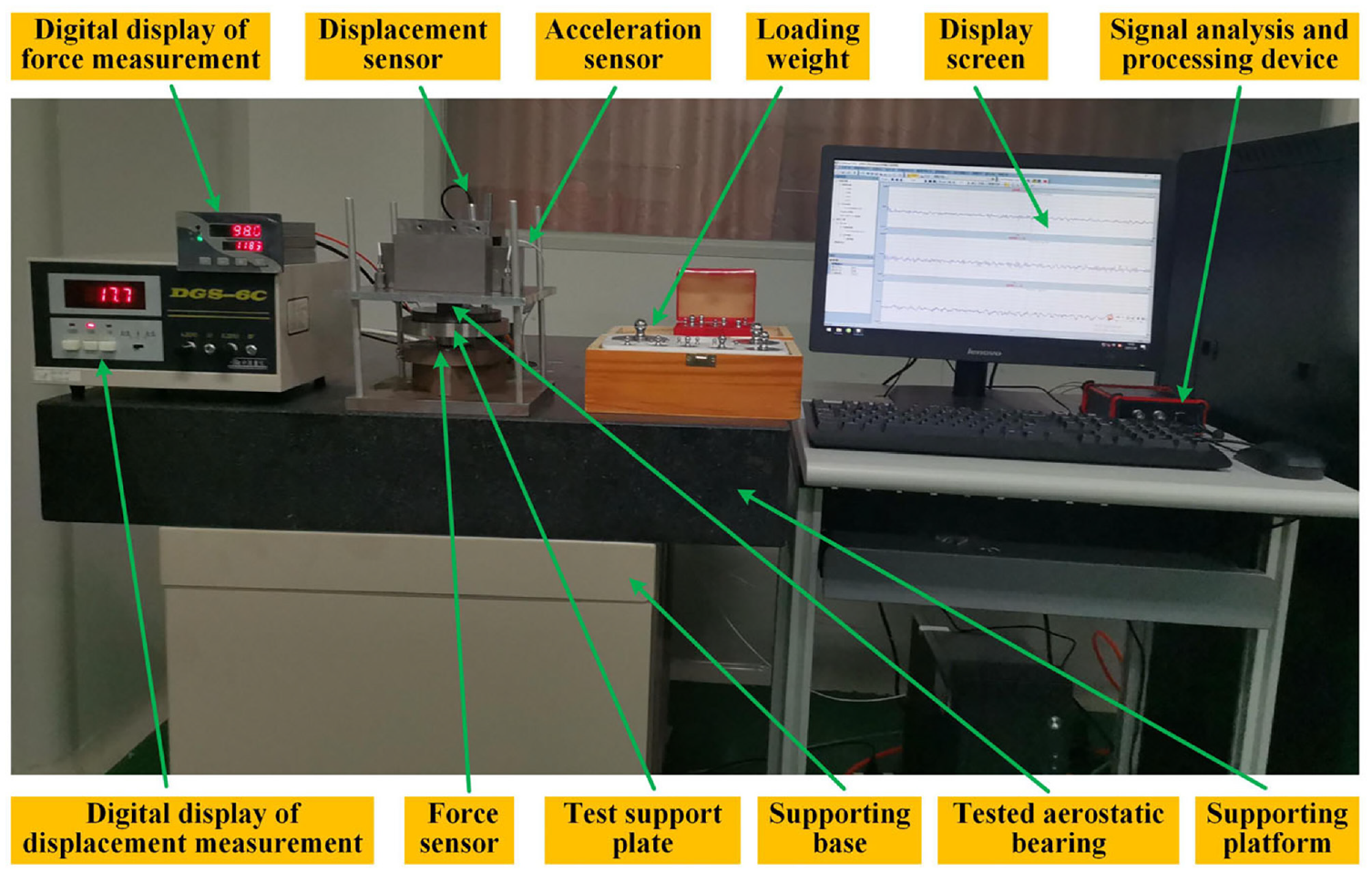
The physical device for micro-vibration test of the MIR aerostatic bearing.
Results and analysis
The dimension parameters of the aerostatic bearing with the single orifice selected for the experimental test are as follows: The overall dimension parameter is ϕ30 mm × 15 mm, the diameter d of the orifice is 0.20 mm, and only one restrictor with one single orifice is arranged at the center of the aerostatic bearing. The physical model of the MIR aerostatic bearing selected for the experimental test is shown in Figure 1, and its overall dimension parameter is ϕ30 mm × 15 mm, the diameter d of the orifice is 0.20 mm, and only one multi-hole integrated restrictor is arranged at the center of the aerostatic bearing. The influence of the gas film clearance h on the micro-vibration of the MIR aerostatic bearing is experimentally tested and researched. The experimental test sample is the MIR aerostatic bearing with the 5 × 0.2, and the gas supply pressure ps is 0.4 MPa, and the gas film clearance h is 10, 15, and 20 μm, respectively. In order to research the micro-vibration amplitude of the MIR aerostatic bearing more intuitively, the vibration acceleration signal is collected by the acceleration sensor, and then converted into the vibration displacement signal by the frequency domain integration method. The experimental test results of the influence of the gas film clearance h on the micro-vibration of the flow field are shown in Figure 11. The experimental collection time period is 400 ms, and the unit g of longitudinal coordinates represents the gravitational acceleration (9.8 m/s2).

Experimental test diagram of the gas film clearance h on the micro-vibration.
As can be seen from Figure 11, with the increase of the gas film clearance h of the MIR aerostatic bearing with the 5 × 0.2, the vibration amplitude of the flow field gradually increases. The variation trend of vibration displacement results is consistent with the fluctuation and variation trend of the pressure and the velocity of the flow field in Figures 4 and 5, indicating that the gas film clearance h has an important impact on the stability of the MIR aerostatic bearing. When the number n of the orifice and the diameter d of the orifice remain unchanged, the increase of the gas film clearance h will cause the increase of the θ value (the ratio between the gas film clearance h and the diameter d of the orifice). The increase of the θ value will inevitably cause the fluctuation trend of the film flow pattern of the flow field to become more and more obvious. Therefore, the increase of the gas film clearance h will increase the amplitude of the micro-vibration of the MIR aerostatic bearing. In practical engineering application, if conditions permit, controlling and reducing the gas film clearance h and the θ value as much as possible can weaken the micro-vibration of the MIR aerostatic bearing.
The influence of the gas supply pressure ps on the micro-vibration of the MIR aerostatic bearing is experimentally studied. The MIR aerostatic bearing with the 5 × 0.2 is used as the experimental test sample, and the gas film clearance h is 10 μm. The gas supply pressure ps is 0.4, 0.5, and 0.6 MPa, respectively. The time domain experimental results of the influence of the gas supply pressure ps on the micro-vibration are shown in Figure 12. It can be seen from Figure 12 that the gas supply pressure ps has a significant influence on the micro-vibration of the flow field. With the gradual increase of the gas supply pressure ps, the amplitude of the micro-vibration gradually increases. Therefore, if the bearing performance conditions allow in practical engineering applications, reducing the gas supply pressure ps is an effective way to weaken and suppress the micro-vibration of the MIR aerostatic bearing.

Experimental test diagram of the gas supply pressure on the micro-vibration.
The effect of the number n of the orifice of the multi-hole integrated restrictor on the micro-vibration is experimentally researched. The number n of the orifice is 5, 9 and 13, respectively, three types of the MIR aerostatic bearing (the 5 × 0.2, the 9 × 0.2, and the 13 × 0.2) and the aerostatic bearing with single orifice (the diameter of the orifice is 0.2 mm and the orifice is located in the center of the restrictor) are used as experimental test specimens. The gas supply pressure ps is 0.4 MPa, and the gas film clearance h is 10 μm. The time domain experimental results of the influence of the number n of orifices on the micro-vibration are shown in Figure 13. It can be seen from Figure 13 that the amplitude of the micro-vibration gradually decreases with the increase of the number n of the orifice of the multi-hole integrated restrictor. The change trend of the number n of the orifice on the micro-vibration can maintain a good change trend from the fluctuation and change trend of the pressure and the velocity of the gas film in Figures 4 and 5. The MIR aerostatic bearing can effectively reduce the amplitude of the micro-vibration by increasing the number n of the orifice of the multi-hole integrated restrictor to a certain extent.

Experimental test diagram of the number of the orifice on the micro-vibration.
From Figures 11 to 13, it can be seen that the gas film clearance h, the gas supply pressure ps, and the number n of the orifice of the multi-hole integrated restrictor have a great impact on the micro-vibration, and the micro-vibration test results are in good agreement with the numerical calculation results of the fluctuation of the flow field. With the increase of the gas film clearance h, the gas supply pressure ps and the decrease of the number n of the orifice of the multi-hole integrated restrictor, the micro-vibration of the flow field will gradually increase. Therefore, when the actual engineering application and bearing performance of the MIR aerostatic bearing allow, the amplitude of the micro-vibration of the MIR aerostatic bearing can be effectively weakened and restrained by controlling and reducing the gas film clearance h and the gas supply pressure ps and increasing the number n of the orifice of the multi-hole integrated restrictor.
Conclusions
The numerical calculation method combined with large eddy simulation and over-relaxation iteration has been used to reveal lubrication characteristics of the flow field at the orifice outlet of the MIR aerostatic bearing. From the results, we have made the following conclusions:
From the fluctuation range of the pressure and the velocity of the gas film, there are obvious the pressure drop and the velocity rise at the orifice outlet, and the lubrication performance of the multi-hole integrated restrictor is better than that of the single-orifice restrictor. The separation of the gas film pressure near the orifice outlet became in consistent in the thickness direction of the gas film clearance, and the lubrication characteristics of the gas film flow field at the orifice outlet have been revealed.
Through the analysis and research of the transient flow field of the MIR aerostatic bearing, it has been proposed to divide the region near the orifice outlet into five regions to analyze and discuss the lubrication characteristics of the flow field, which provides a good means and method for further studying the mutual transition rules between the gas film flow patterns at the orifice outlet.
The influencing factors of the micro-vibration of the MIR aerostatic bearing have been experimentally researched and the multi-hole integrated restrictor can effectively reduce the micro-vibration of the gas film flow field, and the related influencing rules and suppression measures have been discussed. The micro-vibration can be effectively weakened and suppressed by controlling and reducing the gas film clearance and the gas supply pressure and increasing the number of the orifice of the MIR aerostatic bearing. The research on the lubrication characteristics of the flow field will greatly improve the application of the MIR aerostatic bearing in ultra-precision machining equipment.
Footnotes
Handling Editor: Chenhui Liang
Declaration of conflicting interests
The author(s) declared no potential conflicts of interest with respect to the research, authorship, and/or publication of this article.
Funding
The author(s) disclosed receipt of the following financial support for the research, authorship, and/or publication of this article: This research was supported by the National Natural Science Foundation of China (51705390), the Project of Shaanxi Provincial Department of Science and Technology (2022GY-215), Science and Technology Project of Weiyang District (202110), and the Project of Xi’an Science and Technology (21XJZZ0025).