
Abstract
Numerical research is carried out on the cooling performance of an aircraft electromechanical actuator (EMA) using heat pipes. The theoretical model is established to describe the heat transfer processes in the EMA, which is validated by comparing the numerical and experimental results. The heat transfer characteristics of the EMA using two different cooling methods, heat pipes-fuel and heat pipes-ram air, are studied by numerical simulation. For the heat pipes-fuel cooling method, impact of the coolant flow velocity (0–0.015 m/s) on the cooling performance of the EMA is studied, based on which fins are designed on the condenser of heat pipes to improve the cooling performance. The results show that it is an efficient way to cool the electromechanical actuator with heat pipes-fuel cooling method and the heat dissipation rate of the EMA can be improved by 28.8% by using fins. In addition, the heat pipes-ram air cooling method could cool the EMA efficiently with the ram air temperature properly controlled.
Keywords
Introduction
In all-electric aircraft (AEA), the electric power replaced the conventional hydraulic power, pneumatic power, and mechanical power and becomes the only secondary power source on aircrafts.1–3 The use of electromechanical actuator (EMA) in the flight control actuation systems (FCAS) simplified the structure, reduced maintenance, and improved reliability of an aircraft with the elimination of hydraulic sources, hydraulic pump, and pipelines.3,4 However, the EMAs in the FCAS are installed at enclosed spaces (i.e. spoilers and horizontal stabilizers) and appropriate heat sinks are limited, thus cooling problems need to be properly solved.
Traditionally the electronics on aircrafts can be cooled by bleed air from engine, 5 however, using bleed air will reduce the aircraft thrust and flight performance. Phase change materials (PCM) was used to improve peak heat absorption,3,6,7 while the PCM could only act as a buffer of the thermal shock for lowering the temperature peak value of the EMA, and an efficient cooling approach and the heat sink are still needed.
Aircraft skin can be used as heat sinks of the EMA. A two-phase thermosyphon cooler and heat pipes were used to transfer the heat from heat sources to aircraft skin,3,6,8 however, aircraft skin temperature is affected by flight altitude and Mach number. When the flight altitude is between 0 and 16 km and the Mach number is between 0.6 and 2.1, the skin temperature can reach 220–450 K. 5 However, the allowable working temperature of electronics like motor and insulated gate bipolar transistor (IGBT) module is generally around 253–423 K. If the skin temperature is beyond the range of the EMA allowable working temperature, aircraft skin can’t be used as heat sinks of the EMA. Another cooling approach combined the heat pipes and a heat exchanger which can be 9 installed at places where the heat is required such as fuel system and anti-icing system, however, introducing heat exchangers requires additional pumps, pipelines, and flow channel which will increase the complexity of aircraft structure.
Wu et al. comprehensively analyzed the methods of improving the reliability of fan cooling system by using fault tree analysis method to keep the temperature of electric actuator from being too high. According to the characteristics that the flight height and ambient temperature of the driving motor change continuously during the whole flight stage, a variable speed fan with wide range of pressure and temperature is designed. 10 Xu et al. aimed at the severe heating and special heat dissipation conditions of the permanent magnet motor used in the main wheel of large aircraft, they forced the heat generated by the motor to be cooled by the surrounding air flow driven by the fan. Meanwhile, fins were designed on the stator surface to strengthen convective heat transfer and reduce the temperature of the motor. At the same time, the author verifies the CFD simulation method of motor heat dissipation through experimental measurement, and the results show that CFD can be used to predict the thermal performance of the motor under different working conditions. 11 Malu et al. discussed the feasibility of two-phase heat transfer for the heat dissipation scheme of Toyota Prius inverter module. The results show that the heat dissipation performance of IGBT module mainly depends on the type of cooling medium, because the type of cooling medium directly affects the convective heat transfer coefficient. At the same time, the convective heat transfer coefficient is also affected by flow rate, heat generation, channel size, saturation temperature, and so on. 12 Lu et al. proposed to use gravity heat pipe heat exchanger combined with air forced convection for heat dissipation of IGBT module with large size and high power. A substrate is arranged on the surface of IGBT module, the evaporation section of heat pipe is in direct contact with the substrate, and the surface of heat pipe condensation section is equipped with fins. The heat pipe condensation section is cooled by forced ventilation. 13
In conclusion, there are some restrictions in the existing cooling method of the EMA. Cooling the EMA with bleed air would reduce the flight performance. PCM is only suitable to reduce thermal shock. The application of aircraft skin is restricted by the skin temperature. Introducing heat exchangers will increase the complexity of aircraft structure. Thus, an efficient cooling approach is required to transfer the heat directly into proper heat sinks. In this paper, a cooling method for an aircraft EMA based on heat pipes is introduced, and numerical research is carried out to see the effectiveness of this method and the operation characteristics of such a cooling device.
Numerical method of the EMA
The EMA researched in this paper contains a permanent-magnet synchronous motor (PMSM), a reducer, a ball crew, and a driver. Rated values of the EMA are shown in Table 1.
Rated values of the EMA.

Preliminary research 14 on the heat generation and heat transfer characteristics revealed that the main heat-generating components of the EMA is motor, IGBT module, and thyristor.
Cooling method
In this paper, heat pipes-fuel cooling method is used to cool the EMA for following reasons:
(1) Heat pipes are components of high thermal conductivity15,16 which can be used to transfer the heat from the EMA to heat sinks.
(2) There are some restrictions in existing cooling approaches like using heat pipes and aircraft skin to cool the EMA. 5 Fuel can be used to be heat sinks for the electronics on aircrafts. 5
In general, in order to improve the aircraft endurance, lots of fuel is carried and fuel tanks are separately arranged on the fuselage and wing of an aircraft. Pumps and valves are employed to transfer the fuel from one fuel tank to another. After absorbing the heat generated by electronics, oil and hydraulic systems, part of the fuel is supplied to the engine for combustion, and the other part is cooled by the ram air and then returned to fuel tanks,17,18 thus the fuel in fuel tanks continuously flows.
In addition, from literature, 17 when the total heat load on an aircraft reaches 50 kW, in the first 1 h during the flight, the fuel temperature in the central fuel tank is below 303 K. With the consumption of the fuel, fuel temperature gradually increases and eventually reaches 323 K after 2 h which is higher than the minimum allowable temperature and much lower than the maximum allowable temperature of the EMA.
In conclusion, the fuel continuously flows and its temperature is appropriate, the EMAs of spoiler and aileron actuators are close to fuel tanks on the wings, and the EMAs of flap are close to central fuel tank, thus it is a good choice to regard fuel as the heat sink for the EMA.
(3) Rated rotational speed of the PMSM is very small (1500 r/min) and the windings are designed on the stator, thus the major loss of the machine is stator loss,4,19 for which heat pipes are designed on the stator to directly transfer the heat from heat sources to heat sinks. The condenser of heat pipes are immersed into fuel tanks with the fuel flowing through.
This passive cooling method is expected to cool the EMA efficiently without extra pumps, pipelines, and flow channel. In order to minimize the influence of heat pipes on the working performance of the motor, heat pipes are arranged in the slots outside the stator. For the driver, heat pipes can be directly arranged on the surface of electronics. Heat pipes and electronics are bonded with silicone. The heat pipes-fuel cooling system of the EMA is shown in Figure 1.
The heat pipes-fuel cooling system of the EMA.
Considering the economy and the availability of obtaining, copper-water heat pipes are selected. Twelve heat pipes are used to cool the motor stator. For the driver, five heat pipes are used to cool the IGBT module and four heat pipes are used to cool the thyristor. Structural parameters of heat pipes are shown in Table 2.
Structural parameters of heat pipes.

The distribution of the electronics and heat pipes in the driver is shown in Figure 2.

The distribution of the electronics and heat pipes in the driver.
Theoretical model
Governing equations
First, following simplifications and assumptions are made for the EMA:
Heat pipes are regarded as solids, and the heat transfer performance is characterized by the effective thermal conductivity of heat pipes. 20
Assume that the fuel is at three-dimensional (3D) steady state. Though the change of aircraft flight attitude will cause the fuel sloshing and shocking the walls of fuel tanks. Numerical and experimental study21,22 shows that using baffles can effectively reduce the fuel sloshing and the impact of fuel on the walls of fuel tanks, and provide a steady working environment for heat pipes. Thus it can be regarded that when the aircraft flies smoothly or the flight attitude changes slightly, the fuel is at steady state.
Continuity equation:

where u, v, w are respectively the velocity in the x, y, z direction, m/s.
Momentum conservation equation:

where ρ is fluid density, kg/m3; μ is dynamic viscosity, Pa s;
Energy conservation equation in the solid:
where
Energy conservation equation in the fluid:
where cp is specific heat capacity, J/(kg K);
Meshing
Ansys ICEM CFD software is used to generate a 3D unstructured grid of the EMA. As the size of heat pipes is very small compared to the flow channel, the grid around heat pipes is refined to ensure a good quality. 3D unstructured grid of the EMA is shown in Figure 3.

3D unstructured grid of the EMA.
Since the number of grids and their parameters will affect the results of calculation, a reasonable number of grids can be determined through grid independence verification to improve the calculation speed and ensure the solution accuracy of numerical calculation. As shown in Figure 4 for the change of the grid number’s influence on the temperature of the IGBT module, it can be seen in the number of grids in 4 million before the change to the calculation result has a certain influence, when the grid number above 4 million, the change of the grid number on the result of calculation is relatively small. In a grid number greater than 4 million range, the simulation results tend to be stable. Therefore, the mesh of 4.3 million is chosen to run the simulation.
Mesh independence verification.
Boundary condition
The temperature and velocity of the inlet fuel is estimated according to literature. 17 Fuel temperature is defined as 315.5 K. According to the size of fuel tanks in literature, 17 assume the fuel consumption is 0.5 kg/s and the returned fuel is 1 kg/s, the average flow velocity in the flow channel is between 0.000549 and 0.000962 m/s. Thus the fuel velocity is defined as 0.000639 m/s in this study.
The velocity of the fuel is very small, the Reynolds Number is 41.5 when the fuel velocity is at 0.000639 m/s, therefore the laminar model is used in numerical simulation.
Thermal physical parameters
Table 3 shows the materials and thermal physical parameters of the EMA. The effective thermal conductivity of the heat pipe is defined as 7000 W/(m K) in numerical simulation.
Materials and physical parameters of the EMA.
Heat generation rates of the EMA
First, the relation of heat generation from the electric actuator to the thrust and actuating speed of electric cylinder and the relation of driver current to the thrust and actuating speed of electric cylinder are obtained by fitting the data with Matlab software. The reliability of the formula is verified by the heat generation and current of the electric actuator under rated operating conditions. Combined with the relationship between the loss of each electronic component of the driver and the current, the heat generation rate s of the EMA under given velocities and forces are calculated by the formula and the results are shown in Table 4.
Heat generation rates of the EMA under given velocities and forces.

Validation of the model
The experimental setup for the study on the cooling performance of the EMA is shown in Figure 5. Asbestos are used to insulate the heat pipes exposed to air and the walls of the flow channel.

Experimental setup for the study on the cooling performance of the EMA.
The temperature measuring points of the EMA are shown in Figure 6.
The temperature measuring points of the EMA: (a) the measuring points on the outer surfaces of the motor and the ball crew, (b) the measuring points on the windings, and (c) the measuring points of the IGBT module and the thyristor.
Water is selected as the coolant to validate the numerical model with the coolant velocity at 0.000639 m/s, the coolant temperature of 315.5 K, and the environment temperature of 296.9 K. The temperature rise (temperature value − environmental temperature) of the EMA under given working conditions is measured and the results are shown in Figure 7.

Comparison between the experimental results and the numerical results: (a) the EMA and (b) the driver.
The results show that the maximum absolute error (the difference between numerical results and experimental results) of the EMA is 9.7 K (14.5%) which is presented at the outer surface of the motor. The maximum error of the driver is 8.5 K (14.6%) which is presented at the IGBT module. As a whole, the errors are acceptable and the numerical model can be used to study the cooling performance of the EMA.
Cooling performance of the EMA based on two different heat pipe cooling methods
The heat pipes-fuel cooling method
Apart from the environmental temperature and the inlet coolant temperature, the cooling performance of the EMA can also be affected by the coolant flow velocity. Impact of the coolant flow velocity on the cooling performance of the EMA is studied, based on which fins are designed on the condenser of heat pipes to improve the cooling performance of the EMA.
Impact of the coolant flow velocity on the heat pipes-fuel without fins
The temperature rise at the measuring points of the EMA is monitored and the results are shown in Figure 8. It can be seen that the temperature of the EMA decreases with the rise of the fuel velocity. When the fuel velocity is below 0.003 m/s, increasing the fuel velocity will significantly improve the cooling performance of the EMA. However, when the fuel velocity is above 0.003 m/s, such influence is not obvious. From 0.0001 to 0.003 m/s, the temperature rise of the windings decreases by 49 K (43.4%), the IGBT module 50.7 K (55%), and thyristor 32.3 K (50.7%). However, from 0.003 to 0.015 m/s, the temperature rise of the windings decreases by 9.5 K (14.8%), the IGBT module 4.5 K (5.8%), and thyristor 2.6 K (4.3%).
Impact of fuel velocity on the EMA: (a) EMA and (b) driver.
In conclusion, increasing fuel velocity can significantly improve the cooling performance of the EMA especially at low velocities.
The heat pipes with fins at the condenser section
Design of fins structure
Thermal resistance during the cooling process is analyzed by the formula of thermal resistance with the fuel velocity at 0.003 m/s, the fuel temperature of 313.5 K, and the effective thermal conductivity of heat pipes of 7000 W/(m K).

where R is the thermal resistance, K/W; ΔT is the temperature difference, K; Q is the heat transfer rate, W.
For the EMA, the average conduction thermal resistance of heat pipes is 0.048 K/W. The average convection thermal resistance is 0.1014 K/W. The average convection thermal resistance/the average conduction thermal resistance of heat pipes = 2.11. Similarly, for the IGBT module, the average convection thermal resistance/the average conduction thermal resistance of heat pipes = 0.1238/0.0861 = 1.438. For the thyristor, the average convection thermal resistance/the average conduction thermal resistance of heat pipes = 0.135/0.1025 = 1.318. Therefore the main thermal resistance during the cooling process is the convection thermal resistance which needs to be reduced in the cooling design. Fins are commonly used for heat convection enhancement by enlarging the heat transfer area. In this paper, fins structure is designed to improve the cooling performance of the cooling system.
The fin efficiency

where
The ratio of the convection thermal resistance and the conduction thermal resistance of heat pipes is better to be close to 1, which means the convection thermal resistance should be decreased by 2.11 times. Fin efficiency is around 0.5–0.9 for circular fin whose fin height is about 10–20 mm,
23
suppose
Annular fins are employed due to the low flow resistance and the convenient fabrication process. Fin thickness is around 1–3 mm in most study.24–26 Usually if the structure is satisfied for the requirement of strength, it is advised to choose thinner structure. In this paper, to avoid the damage of fins in practical application and for the convenience of meshing in numerical simulation, the thickness of fins is designed to be 1.6 mm. In addition, considering the heat transfer capacity of fins might be influenced if the spacing of fins is too small, the spacing of fins is designed to be 11 mm, and 15 rows of fins can be arranged on the condenser of heat pipes. Surface area of finned heat pipes is 0.3963 m2, which meets the requirement of fins design. The structure of the finned heat pipes for the EMA is shown in Figure 9.

The structure of the finned heat pipes for the EMA.
Similarly, the surface area of finned heat pipes for the IGBT module is around 0.0835 m2, and for the thyristor is 0.0612 m2, thus the total area is around 0.1447 m2. The parameters of fins for the driver are shown in Table 5, and the structure is shown in Figure 10.
Structure of fins for the driver.


The structure of the finned heat pipes for driver.
Cooling performance of the heat pipes-fuel with fins at the condenser section
The temperature of the EMA with/without fins is shown in Figure 11, in which line a corresponds to 0.0001 m/s, line b 0.003 m/s, and line c 0.015 m/s. It can be seen that from 0.0001 to 0.003 m/s, the temperature rise of the windings is decreased by 36.2 K (42.2%), the IGBT module 28.2 K (46.6%), and thyristor 28.5 K (49.6%). However, from 0.003 to 0.015 m/s, the temperature rise of the windings decreases 3.5 K (7%), the IGBT module 2.5 K (7.6%), and thyristor 2.4 K (8.1%). The same conclusion can be drawn that increasing fuel velocity can significantly improve the cooling performance of the EMA especially at low velocities.
Temperature rise of the EMA with fins.
In addition, introducing fins can reduce the temperature rise of the EMA by 13.3%–35.5%, the temperature rise of the driver by 4.5%–34%. The heat dissipation rate of the EMA is improved by 28.8% (Figure 12) while the pressure loss is very small that can be ignored (Figure 13).
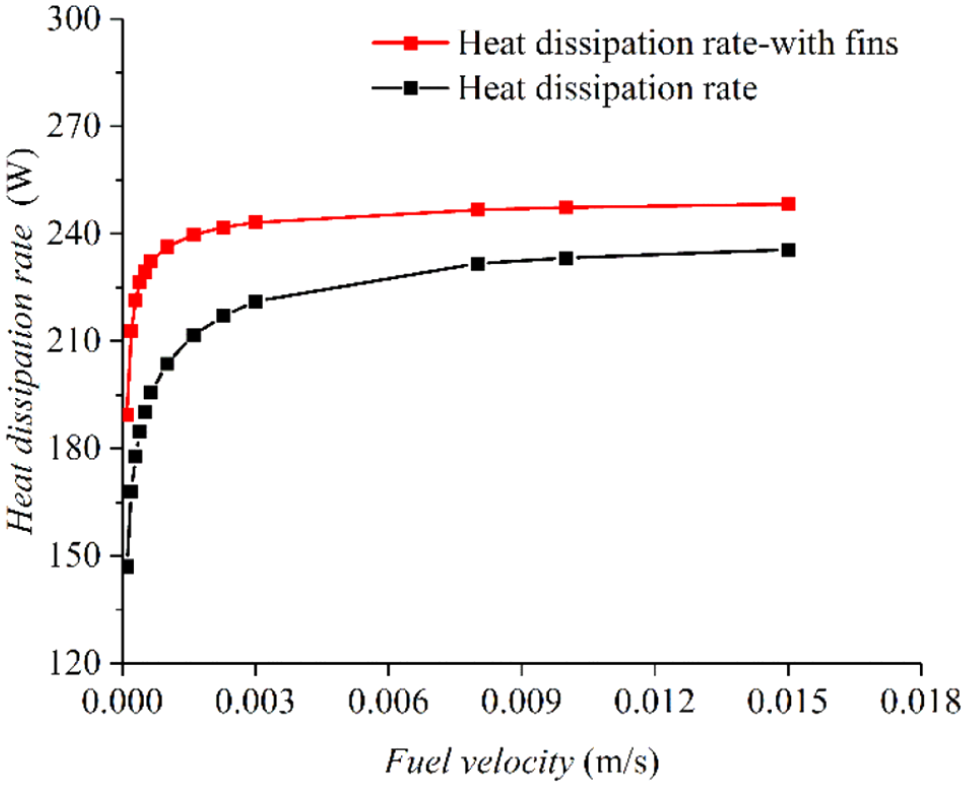
Heat dissipation rate during the heat pipes-fuel cooling process under different flow velocity.

Pressure loss of the cooling system under different flow velocity.
In conclusion, the designed fins can obviously improve the cooling performance of the EMA while produce little pressure loss.
The heat pipes-ram air cooling method
Ram air is an accessible heat sink on aircrafts. It is commonly used to cool the electronics and heat exchangers in the environment control system. 27 Ram air flow channel is usually arranged on the fuselage or wing of an aircraft. The EMAs are also installed on the fuselage and wing of an aircraft, thus ram air could be used to cool the EMA. The cooling performance of the EMA based on heat pipes-ram air is also studied.
Parameters of the ram air
Study28,29 reveals that the velocity and temperature of ram air are mainly affected by the altitude and Mach number. Thermal physical parameters of the ram air before heat exchangers under different flight phases are obtained based on the structure of flow channel shown in Figure 14. The size of the flow channel at the entrance is 140 mm × 140 mm and the size of the flow channel arranged with heat exchangers is 200 mm × 200 mm.

Structure of the ram air flow channel.
The temperature, pressure, and density of the air before the entrance of the flow channel under given altitude and Mach number are acquired by following formulas. 29
Troposphere (0 < H < 11 km):


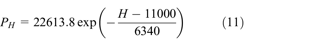
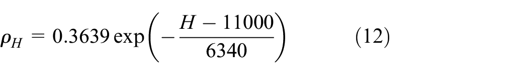
where H is the altitude, m; TH is the atmospheric temperature at the altitude of H, K; Te is the atmospheric temperature when H = 0 m, Te = 296.9 K; a is environmental lapse rate, a = 0.0065 K/m; PH is the atmospheric pressure at the altitude of H, kPa; Pe is the atmospheric pressure when H = 0m and Te = 296.9 K, Pe = 101.325 kPa; g is gravitational acceleration, g = 9.8 m/s2; Rg is the gas constant, Rg = 287 J/(kg K); ρH is the atmospheric density at the altitude of H, kg/m3; ρe is the atmospheric density when H = 0 m, kg/m3.
Stratosphere (11 km < H < 20 km):

Total temperature:

where MH is Mach number;
Total pressure:

where
Calculated temperature, pressure, and density of the air before the entrance of flow channel under given flight phases 6 are shown in Table 6.
Parameters of the air before the entrance of flow channel under given flight phases.

When MH > 1, a normal shock might be generated before the entrance of the ram air flow channel. The physical parameters of the ram air after the normal shock can be calculated by following formulas.
Total temperature of the ram air after the normal shock
Mach number of the ram air after the normal shock M1:

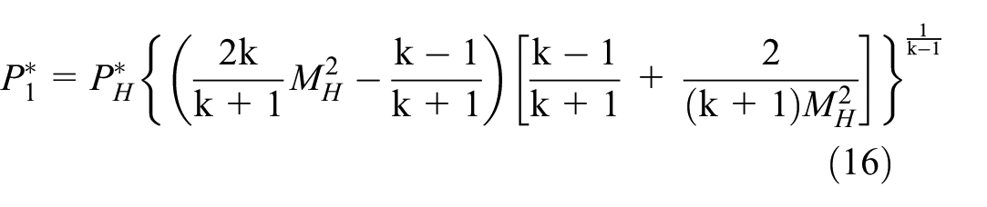
Total pressure of the ram air after the normal shock

Mach number at the entrance of the flow channel M2 = 0.4M1.
Total pressure recovery coefficient before the entrance of the flow channel to the entrance of the flow channel σ1 is 0.99, total pressure recovery coefficient from the entrance to heat exchangers σ2 is 0.97, then the total pressure before the heat exchangers

Total temperature before the heat exchangers
The continuity equation is as follows:

where ρ2 is the density of the air at the entrance of the flow channel, kg/m3; V2 is the velocity of the air at the entrance of the flow channel, m/s; A2 is the area of the flow channel at the entrance, m2; ρ3 is the density of the air at the entrance of the flow channel, kg/m3; V3 is the velocity of the air before the heat exchangers, m/s; A3 is the area of the flow channel before the heat exchangers, m2.
According to the above formulas, the parameters of the ram air before heat exchangers under given flight phases are shown in Table 7.
Parameters of the ram air before heat exchangers under given flight phases.

The results show that the ram air temperature before heat exchangers can be approximate to the total temperature as the two values are very close. Total temperature of the ram air is mainly affected by the altitude and Mach number of an aircraft. At the same altitude, the total temperature increases with the Mach number. In the troposphere, the total temperature decreases as the altitude increases at the same Mach number.
Cooling performance of the heat pipes-ram air with fins at the condenser section
The physical model of the EMA is the same as the model with fins in Chapter 3.1.2.2. The maximum Mach number of the ram air before heat exchangers is 0.15 (less than 0.3), thus the air can be regarded as incompressible gas. In Table 7, the Reynolds number of the ram air before heat exchangers is more than 1.78 × 10⁵, so standard k-ε turbulence model is employed as this model is stable and accurate enough for simulation. The temperature and velocity of the ram air is given according to Table 7.
The numerical results are shown in Figure 15. It can be seen that when the heat generation rates of the EMA keep constant, the temperature rise of the EMA decreases from phase 1 to phase 2, increases from phase 2 to phase 3, and then decreases from phase 3 to phase 4. The temperature rises and falls frequently and even might be higher than the maximum allowable temperature or lower than the minimum allowable temperature of the EMA, which will significantly affect electronics’ working performance, reduce their working life, and even causes the electronics failed.

Comparison of the heat pipes-fuel cooling system and the heat pipes-ram air cooling system: (a) the EMA and (b) the driver.
In addition, comparing the heat pipes-fuel cooling method and the heat pipes-ram air cooling method, it is found that when the fuel velocity is higher than 0.0002 m/s, during phase 3 and phase 5, the heat pipes-fuel cooling method is superior to the heat pipes-ram air cooling system, while during other phases, the cooling performance of the heat pipes-ram air cooling method is better.
In conclusion, the heat pipes-fuel cooling method is suitable to cool the EMA because it has good cooling performance, the fuel temperature won’t dramatically fluctuate and circumstances like the coolant temperature is lower than the minimum allowable temperature or higher than the maximum allowable temperature won’t occur. If the above problems can be properly solved, it is also an efficient way to cool the EMA using ram air.
Conclusions
The cooling performance of an aircraft EMA based on heat pipes was investigated by numerical simulation. The conclusions are as follows:
It is an efficient way to cool the EMA with heat pipes-fuel cooling method, and this passive cooling method doesn’t need extra pumps, pipelines, and flow channel.
When the fuel velocity is below 0.003 m/s, increasing the fuel velocity will significantly improve the cooling performance of the EMA, however when the fuel velocity is above 0.003 m/s, such influence is not obvious.
With the designed fins, the temperature rise of the EMA is decreased by 13.3%–35.5%, the temperature rise of the driver is decreased by 4.5%–34% and the heat dissipation rate of the EMA is increased by 28.8%.
Influenced by the flight altitude and Mach number, the ram air temperature fluctuates frequently and the total temperature of the ram air may be lower than the minimum allowable temperature or higher than the maximum allowable temperature of the EMA. In this case, the ram air is not suitable to cool the EMA. If the above problems can be properly solved, it is also an efficient way to cool the EMA using ram air.
Footnotes
Handling Editor: Chenhui Liang
Declaration of conflicting interests
The author(s) declared no potential conflicts of interest with respect to the research, authorship, and/or publication of this article.
Funding
The author(s) received no financial support for the research, authorship, and/or publication of this article.