
Abstract
The marine multi-gearbox system has the characteristics of multi-source excitation and multi-gearbox coupled. The interaction among gearboxes is inevitable. To reveal the coupled mechanism, a coupled dynamic model of multi-gearbox system is proposed in this paper by the generalized finite element method and the substructure method. The dynamic model of each gearbox in the multi-gearbox system is also established. Under the same working conditions, the dynamic response of single gearbox and multi-gearbox system are obtained. The results show that the adjacent gear pairs of adjacent gearboxes are more affected by the coupled effect at low rotational speed. Compared with single gearbox, the RMS curve of multi-gearbox system of meshing forces generates some new resonance peaks, which are caused by the new modes excited by the mesh frequencies of adjacent gearboxes. The dynamic response of gear pairs which are greatly affected by coupled effect are more sensitive to the change of stiffness of couplings. Reducing the stiffness of the couplings can weaken the coupled effect of the system, and vice versa. The change of housing stiffness does not influence the coupled effect of the multi-gearbox system, and the new modes and resonance peaks generated by the coupled effect have not changed significantly.
Introduction
A gas turbine, steam engine, diesel engine, and electric motors are the main power sources used in ships. With the increasing demand for fuel economy and reliability of ships, the multi-gearbox system has been widely used in large powered ships.1,2 The Multi-gearbox system has various configurations, which are generally composed of parallel gearbox, cross-connect gearbox, and two-speed gearbox, etc. 3 The gearboxes are connected by couplings. The power of multiple engines can be transmitted to the propeller shafts respectively or simultaneously by multi-gearbox system. For multi-gearbox system, each gear pair is an excitation source, so it is a complex multi-source excitation system. The gearboxes inevitably have interaction. Therefore, it is of great significance to study the coupled vibration characteristics of multi-gearbox system.
The research on coupled characteristics of gear system mainly focuses on coupled of degree of freedom, coupled between stages and coupled of supporting system. For the degree of freedom coupling, the gear dynamics model has undergone a pure torsion model, a bending-torsion coupled model and a bending-torsion-axial-swing coupled model (full degrees of freedom). The research found that the full degrees of freedom coupled model can more accurately analyze the vibration characteristics of the system.4,5 Regarding the coupled between stages, the coupled dynamic characteristics of multi-stage parallel shafts and multi-stage planetary gear systems have attracted the attention of many researchers over the years. Papers by Walha et al., 6 Raclot and Velex, 7 and Shen et al. 8 studied the two-stage spur gear system, and found the coupled vibration effect. Zhu et al. 9 established the coupled dynamics model of the middle and tail gearboxes of the helicopter. They found that the diaphragm coupling has a significant effect on the vibration response of the coupling system. Qiao et al. 10 and Kubur et al. 11 found that the flexible shaft can isolate the vibration transmission between two gear pairs. Li et al. 12 studied the influence of precision and damping on the vibration response of two-stage spur gear. Wei et al. 13 summarized several different types of vibration modes and revealed that changes in bearing stiffness not only affect the vibration modes of adjacent stages of the planetary gear train but also affect non-adjacent stages. Sun et al. 14 found that the coupling of the multi-stage planetary gear system increases as the frequency decreases. Wang et al. 15 showed that inter-stage coupled mainly exists in low-mode regions. Sun et al. 14 and Zhang et al. 16 studied the influence of coupling shaft stiffness on the system mode.
Considering the housing support characteristics in the gear dynamic model can more accurately predict the dynamic response of the system. Vazquez 17 used the transfer matrix method to find that the flexibility of the housing plays an important role in rotating machinery. Ren et al.18,19 used the impedance method to consider the housing and pedestal in the gear dynamic model. Lu et al. 20 used the substructure method to extract the mass and stiffness parameters of the housing. Jia et al. 21 and Qin et al. 22 used the dynamic sub-structure method and the lumped mass method to establish the coupled dynamics model of the drum driving system.
For gear system dynamic modeling, lumped mass method and finite element method are widely used.11,23,24 To reduce the degree of freedom of the system model, Choy et al.25,26 used the modal synthesis method to convert the motion equation of the multi-stage gear system into modal coordinates. Kubur et al. 11 and Kang and Kahraman 27 were verified through experiments that the linear model can predict the dynamic response of helical gear system and double helical gears system. In recent years, the dynamics of double-helical planetary gears28–32 and single-stage parallel-axis double-helical gears33–36 have attracted the attention of many scholars. The middle shaft of the helical gear is connected by beam element. The beam element is simulated by the Euler beam model or the Timoshenko beam model. Sondkar and Kahraman 24 proposed the linear time-invariant model of double-helical gears by the Euler beam model and the experiments show that the proposed linear time-invariant dynamic model of double-helical gears can reliably predict the dynamic response of double-helical gears. 27 Dong et al. 33 and Wang et al. 36 used the Timoshenko beam to simulate the intermediate shaft end of a double helical gear and verified the accuracy of the model through experiments.
As published literature mentioned above, there are few studies on the dynamic model of the complex system composed of multiple gearboxes and the coupled characteristics of the system under multi-source excitation. The purpose of this paper is to establish a coupled dynamic model of multi-gearbox to study the coupled mechanism between gearboxes and the influence of the stiffness of couplings and housing on the vibration response of the system. The rest of this paper is organized as follows: In Section 2, a coupled dynamic modeling method for multi-gearboxes based on generalized finite element method and sub-structure method is proposed. Section 3 introduces the coupled dynamics model solving method based on the Fourier series method. Section 4 analyzes the natural frequency and dynamic response of single gearbox and multi-gearbox system. Furthermore, the dynamic response of the multi-gearbox system under different stiffness of couplings and housing are analyzed. Section 5 draws some conclusions from the numerical results.
Dynamic model of the multi-gearbox system
Multi-gearbox system structure and model discretization
As shown in Figure 1(a), the multi-gearbox system with two-input power and two-output power is studied in this paper. It is composed of five gearboxes, in which all gears are double-helical gears. The left and right helical gear in each double-helical gear pair, bearings, and shafts are serially numbered. As shown in Figure 1(b), GB2 and GB4 adopt multi-mesh gear transmission, which can realize the power split and confluence. When the input power of an engine on one side is less than the power required by the load torque of the propeller, the engine on the other side split part of the power through GB2 or GB4 and transmits the power through GB3 to GB2 or GB4 on the power demand side confluence to achieve power distribution.

The diagram of multi-gearbox system with two-input power and two-output power: (a) structure diagram and components number of multi gearbox system and (b) 3D model of GB2 and GB4.
Compared with the lumped mass method, the generalized finite element method can better consider the characteristics of the shaft and support system. Its modeling and solution efficiency are higher than the dynamic three-dimensional contact finite element method. The literature11,37 has verified its validity and accuracy by comparing with experiments and centralized mass method. For multi-gearbox system, it is necessary to ensure the accuracy of the dynamic model and to consider the convenience of modeling. The generalized finite element method is very suitable for such complex models. The model takes the effects of bearing support position and housing flexibility on the dynamic characteristics of the system into consideration. As shown in Figure 2, the multi-gearbox system is discretized into several shaft elements, meshing elements, bearing-housing elements, housing-foundation elements, and coupling elements. By establishing the dynamic model of each element, the overall system dynamic model is obtained by assembling according to the connection relationship between the elements.

Generalized finite element model of two-input and two-output gear transmission system.
Subsystem model
Meshing element
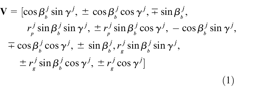
The double-helical gear is modeled as two helical gears. The intermediate shaft is regarded as a shaft element, and it is simulated by the Timoshenko beam element. The calculation of time-varying mesh stiffness adopts the method of Chang et al. 38 As shown in Figure 3, project the displacement from the global coordinate system to the normal line of action. The projection vector V of the jth gear pair is
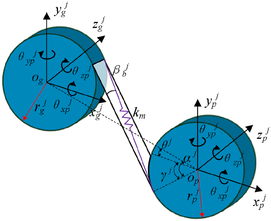
The dynamic model of helical gear pair.
where
The coordinate of the meshing element can be defined as

The motion equations for a helical gear pair can be written as
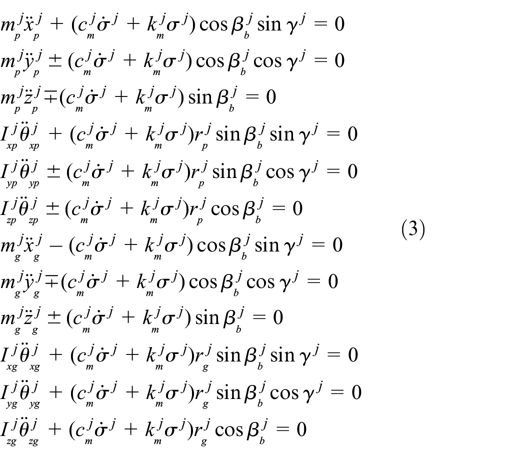
where
The calculation formula of meshing damping

where
The matrix form of the dynamic equation of the meshing element is shown in equation (5).

where
Shaft element
Using the Timoshenko beam element with two nodes to establish the shaft element, as shown in Figure 4. The generalized coordinates of the jth shaft element can be defined as

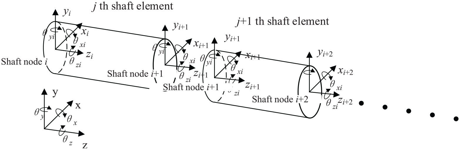
The dynamic model of the shaft element.
Where xj, yj, zj, xj+1, yj+1, zj+1 is the lateral displacement of the node along each coordinate axis, and θ xj , θ yj , θ zj , θx(j+1), θy(j+1), θz(j+1) is the torsion angle of the node around each coordinate axis. The calculation method of the stiffness matrix and the element mass matrix of the shaft element can refer to Stringer. 39
The matrix form of the dynamic equation of the shaft element is:

Where

Where α0 is the mass coefficient, α1 is the stiffness coefficient.
Bearing-housing element
As shown in Figure 5 is the jth bearing-housing element, one end node of the bearing-housing element is at the midpoint of the bearing, and the other end node is at the housing node, that is, at the center hole of the bearing seat. The bearing stiffness matrix


where
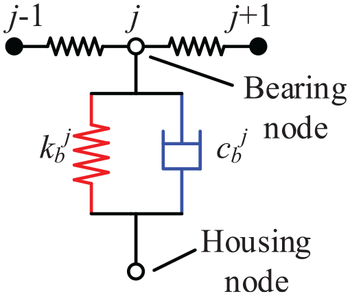
The dynamic model of the bearing-housing element.
Housing-foundation element
To realize the establishment of the coupled dynamic model of the gear rotor system and the housing, the static sub-structure method is used to extract the housing equivalent mass matrix and stiffness matrix in Ansys software. As shown in Figure 6 is the jth housing-foundation element. The housing-foundation element is composed of housing nodes and foundation. There is a coupled relationship between housing nodes. Coupled all nodes on the inner surface of the bearing seat of the gearbox to the central node through rigid beam elements. The central node is defined as a super-element and the main degrees of freedom are applied. The bottom of the housing is fully constrained. The super-element equivalent mass matrix

The dynamic model of the housing-foundation element.
The motion equation for the housing-foundation element can be expressed as:

where
Coupling element
The multi-gearbox system uses a diaphragm coupling. The structure of the diaphragm coupling is shown in Figure 7, which is mainly composed of three parts: the driving end, the driven end, and the coupling diaphragm. The driving end and driven end can be considered as two shaft nodes, each node has six degrees of freedom, the stiffness between the two nodes is the radial stiffness of the coupling diaphragm kcxx, kcyy, axial stiffness kczz, bending stiffness kθxx, kθyy, torsional stiffness kθzz. Among them, kcxx = kcyy, kθxx = kθyy.

The dynamic model of the coupling element.
The stiffness matrix of the coupling element can be expressed as equation (12), where


The motion equation for the jth coupling element can be expressed as equation (14).

Where
Overall system dynamics model
For the multi-gearbox dynamic model considering the housing, the overall stiffness matrix composition is shown in Figure 8. When the block in the figure is composed of two kinds of shadows, the submatrix is the superposition of the corresponding element submatrixes. If the housing is rigid, the rows and columns where the housing is free can be crossed out. There are different types of elements in the system, so it is necessary to assemble the element matrix into the whole matrix in turn.

Schematic diagram of system overall stiffness matrix.
Assemble the mass, stiffness, and damping matrices of each element divided above according to the physical connection relationship, and establish a linear time-varying multi-gearbox coupled dynamic model considering the time-varying meshing stiffness. The system is discretized into 236 nodes, each with 6 degrees of freedom. The motion equation for the system is

Where
To compare and analyze with the coupled system, the dynamic model of each gearbox in the multi-gearbox system is established by using the above method, and these models are not repeated in this paper.
Solution model of the dynamic model
The system dynamics model established in this paper has many nodes, many degrees of freedom, and a large matrix dimension, so the Fourier series method is used to solve the dynamic equations to improve the calculation efficiency. According to the idea of the constant parameter in the Fourier series method, the variable in equation (15) is expressed as the sum of the mean value and the fluctuation value, then

Arrange the shift term to obtain equation (17), where
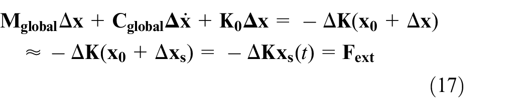

At this time, only the left side of the equation has unknowns, and


Substitute equations (19)–(22) into equation (17) to make the sine and cosine terms on both sides of the equation equal, and satisfy the equation (23) for any order frequency. cn and dn are known, an and bn can be calculated. Then an and bn of each order are substituted into equation (19) to obtain the displacement fluctuation

Dynamics analysis of multi-gearbox system
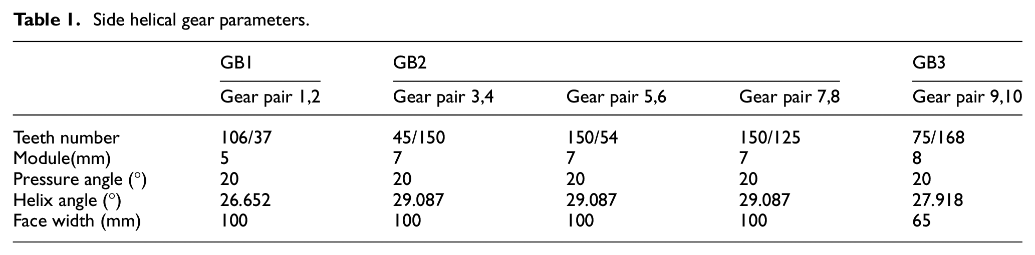
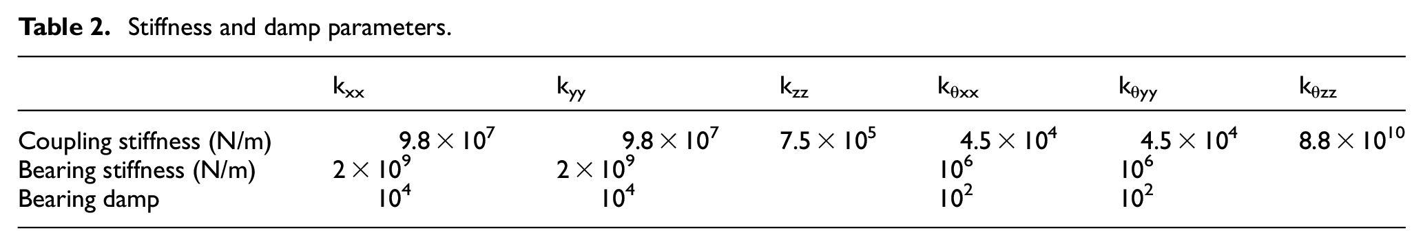
As shown in Figure 9, compared with a single gearbox, the multi-gearbox system is a complex multi-source excitation system with multiple excitation forces of different frequencies. For the convenience of analysis and discussion, the time-varying mesh stiffness excitation is considered in this paper. The mesh frequency of GB1, GB2, and GB3 in the multi-gearbox system is expressed as fm1, fm2, and fm3 respectively. To reveal the coupled mechanism of the multi-gearbox system, this section will analyze the natural frequency difference between the multi-gearbox system and the single gearbox, the coupled effect of multiple gearbox system, and the influence of the stiffness of couplings and housings. The model parameters in this paper are shown in Tables 1 and 2. The parameters of GB4 are the same as GB2, and the parameters of GB5 are the same as GB1. Due to the symmetrical structure of the multi-gearbox system, the dynamic responses of GB1, GB2, and GB3 are analyzed below.

Schematic diagram of double gearbox coupled vibration.
Side helical gear parameters.
Stiffness and damp parameters.
Natural frequency analysis of single gearbox and multi-gearbox system
The natural frequencies of the multi-gearbox system and the single gearboxes GB1, GB2, and GB3 in the system are calculated by equation (25). Among them, [

Natural frequency of single gearbox and multi-gearbox system(Hz).

Coupled effect of multi-gearbox system
Gearbox 1
Under the same working conditions, the dynamic meshing forces of multi-gearbox system and single gearbox are compared. The dynamic transmission error and dynamic meshing force are calculated by equations (25) and (26). As shown in Figure 10(a) is RMS of dynamic meshing force of No.1 meshing element of multi-gearbox system and single gearbox in GB1. It can be seen that there are some new resonance peaks in the RMS curve of the dynamic meshing force of the multi-gearbox system before 415 rpm, and the corresponding resonance speeds are 35, 115, 260, and 385 rpm. After 415 rpm, the RMS curves of dynamic meshing force of multi-gearbox system and single gearbox coincide. Figure 10(b) shows the spectrogram of the dynamic meshing force of the No.1 meshing element of the multi-gearbox system at 0–1000 rpm. It is observed that in addition to the frequency components of GB1′s mesh frequency fm1 and 2fm1, the meshing frequency component fm2 of GB2 is also very significant before 415 rpm.


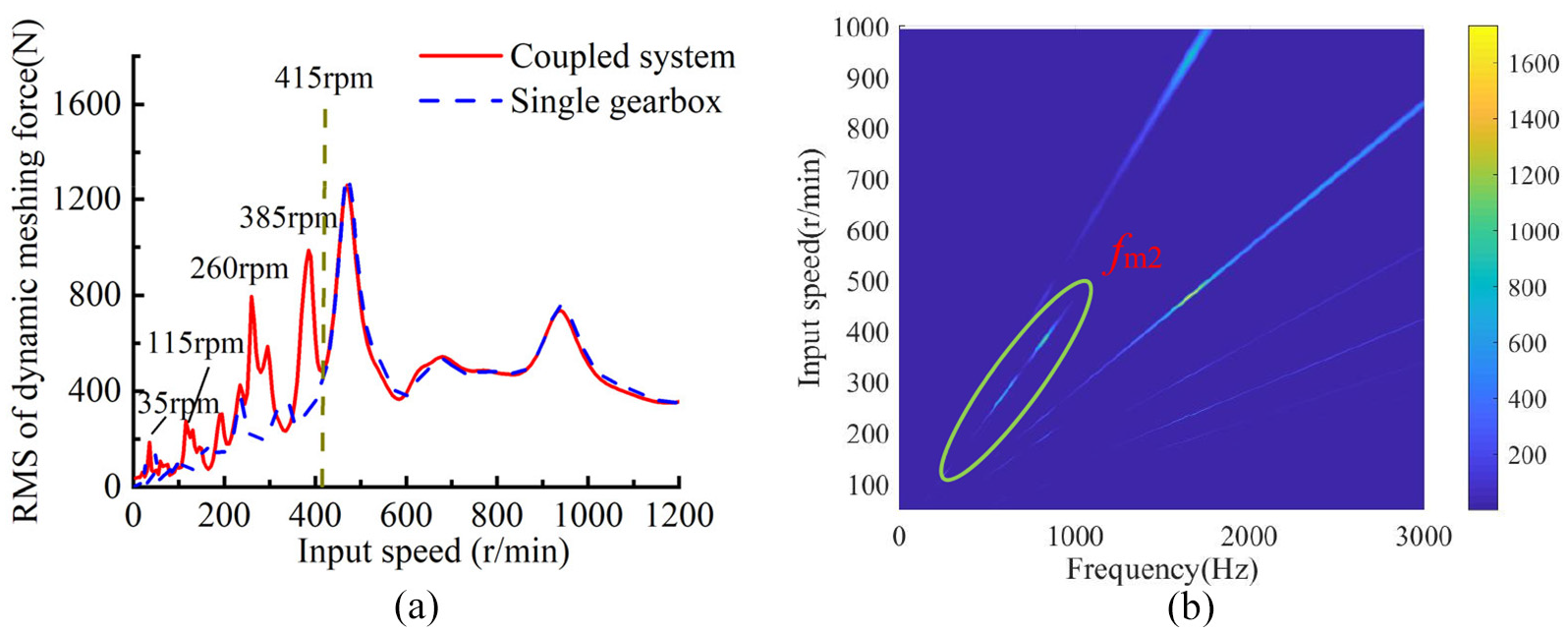
RMS of dynamic meshing force and spectrogram of No.1 meshing element in GB1: (a) comparison of RMS of dynamic meshing force of No.1 meshing element between multi-gearbox system and single gearbox and (b) spectrogram of No.1 meshing element of multi-gearbox system at 0–1000 rpm.
The time domain and frequency domain of dynamic meshing force of No.1 meshing element in GB1 are compared between multi-gearbox system and single gearbox at 385 rpm. As shown in Figure 11(a), The fluctuation of meshing force of No.1 meshing element in multi-gearbox system is 3910 N, and that of No.1 meshing element in single gearbox is 1117 N, which increases by 2.5 times after coupled. It can be seen from Figure 11(b) and (c) that the increase of fluctuation is mainly due to the frequency component of fm2 appearing after coupled, which accounts for a large proportion in the spectrogram.

Time and frequency domain of dynamic meshing force of No.1 meshing element in multi-gearbox system and single gearbox at 385 rpm: (a) dynamic meshing force of multi-gearbox system and single gearbox, (b) the spectrum of single gearbox,and (c) the spectrum of multi-gearbox system.
The mesh frequencies and the corresponding natural frequencies of the system at 35, 115, 260, and 385 rpm are shown in Table 4. At these four resonance speeds, the mesh frequency fm1 of No.1 meshing element does not have the corresponding system natural frequency, but the mesh frequency fm2 of GB2 corresponds to the system natural frequency, which makes the system resonate. It is worth noting that the natural frequencies of the 33rd, 110th, 193rd, and 243rd order systems are all new modes generated by the coupled of multiple gearboxes. Figure 12 shows the mode shape corresponding to the natural frequencies of order 33, order 110, order 193, and order 243. All these modes exhibit the coupled lateral-rotational motions of shaft2 and shaft3. Shaft1 has no motions. Therefore, in Figure 10, resonance peaks are generated at 35, 115, 260, and 385 rpm.
The mesh frequencies at 35, 115, 250, and 385 rpm and the corresponding system natural frequency.


Mode shapes of shaft2 and shaft3: (a) 243rd mode shape, (b) 193rd mode shape, (c) 110th mode shape, and (d) 33rd mode shape.
Gearbox 2
As shown in Figure 13(a) is RMS of dynamic meshing force of No.3 meshing element of multi-gearbox system and single gearbox in GB2. It can be seen that there are some new resonance peaks in the RMS curve of the dynamic meshing force of the multi-gearbox system before 335 rpm, and the corresponding resonance speeds are 260 and 300 rpm. After 335 rpm, the RMS curves of dynamic meshing force of multi-gearbox system and single gearbox coincide. The RMS of the dynamic meshing force of the single gearbox No.3 meshing element has a resonance peak at 279 rpm, but there is no resonance peak in the multi-gearbox system. Figure 13(b) shows the spectrogram of the No.3 meshing element of the multi-gearbox system. The spectrogram of the No.3 meshing element only has its mesh frequency. There is no meshing frequency component of adjacent gearbox GB1 in the spectrogram.

RMS of dynamic meshing force and spectrogram of No.3 meshing element in GB2: (a) comparison of RMS of dynamic meshing force of No.3 meshing element between multi-gearbox system and single gearbox, (b) spectrum diagram of No.3 meshing element of multi-gearbox system at 0–1000 rpm.
The mesh frequencies and the corresponding natural frequencies of the system at 260, 279, and 300 rpm are shown in Table 5. fm2 at 260 rpm corresponds to the 193rd order natural frequency of the system. fm2 at 300 rpm corresponds to the 209th natural frequency of the system. The shaft3 of GB2 exhibits coupled lateral-rotational motion at these two orders. The shaft4 of GB2 has no motions. The mesh frequency of a single gearbox at 279 rpm does not have a close natural frequency in a multi-gearbox system. This shows that some natural frequencies of GB2 have changed after coupled, which changes the dynamic response of the system.
The mesh frequencies at 260, 279, and 300 rpm and the corresponding system natural frequency.

Figure 14(a) shows RMS of dynamic meshing force of No.7 meshing element of multi-gearbox system and single gearbox in GB2. No.7 meshing element is adjacent to GB3. It can be seen that the resonance peak and speed of the curve after coupled multiple gearboxes have changed significantly. Figure 14(b) shows the spectrogram of the No.7 meshing element of the multi-gearbox system. The mesh frequency fm3 of GB3 and its double frequency 2fm3 have great amplitude. This is because the meshing frequency of GB3 makes the system resonate. As shown in Figure 15, the mesh frequencies of GB2 and GB3 make the system resonate at 340 rpm, and the amplitudes of fm2 and fm3 in the spectrogram are both large.
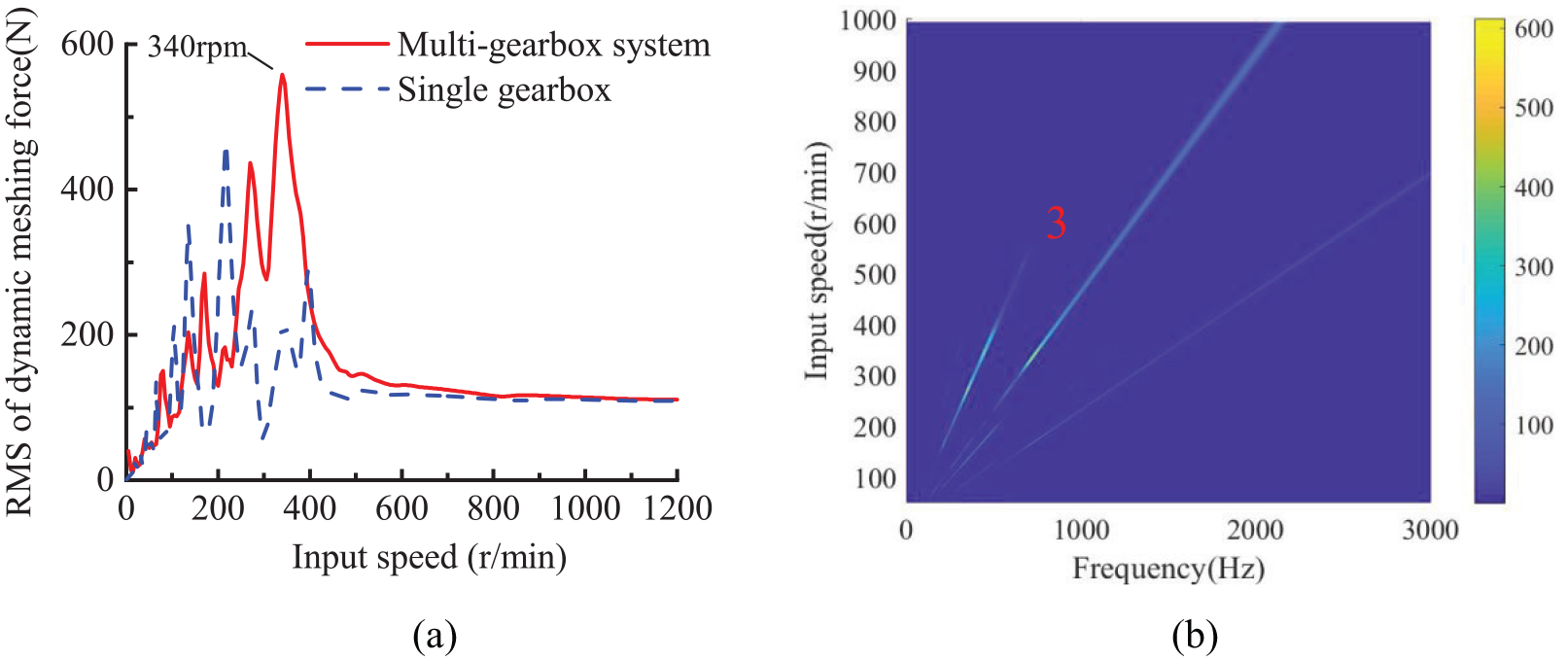
RMS of dynamic meshing force and spectrogram of No.7 meshing element in GB2: (a) comparison of RMS of dynamic meshing force of No.7 meshing element between multi-gearbox system and single gearbox and (b) spectrum diagram of No.7 meshing element of multi-gearbox system at 0–1000 rpm.

The spectrum of No.7 meshing element at 340 rpm for multi gearbox system and single gearbox.
For the No.5 meshing element of GB2, it is not adjacent to GB1 and GB3, so coupled multiple gearboxes do not affect its response. Figure 16(a) shows the RMS curve of the meshing force of the No.5 meshing element of the multi-gearbox system and the single-gearbox. It can be seen that the curves coincide, indicating that the modes are not affected by the coupled. As shown in Figure 16(b), the meshing force spectrogram of the No.5 meshing element only has its meshing frequency and its double frequency.

RMS of dynamic meshing force and Spectrogram of No.5 meshing element in GB2: (a) comparison of RMS of dynamic meshing force of No.5 meshing element between multi-gearbox system and single gearbox and (b) spectrum diagram of No.5 meshing element of multi-gearbox system at 0–1000 rpm.
Gearbox 3
The cross-connect gearbox GB3 is less affected by the coupling effect. As shown in Figure 17(a), the RMS curve of the meshing force of the No. 9 meshing element of the multi-gearbox system and the single gearbox coincides. As shown in Figure 17(b), there is only the meshing frequency component of GB3 in the spectrogram.

RMS of dynamic meshing force and spectrogram of No.9 meshing element in GB3: (a) comparison of RMS of dynamic meshing force of No.9 meshing element between multi-gearbox system and single gearbox and (b) spectrum diagram of No.9 meshing element of multi-gearbox system at 0–1000 rpm.
It is found that the adjacent gear pairs of adjacent gearboxes are more easily affected by the coupled effect. In the multi-gearbox system, the RMS of the dynamic meshing force of the No.1 meshing element and the No.7 meshing element generate some new resonance peaks with larger amplitudes, which are caused by the new modes excited by the mesh frequencies of adjacent gearboxes. The frequency components of adjacent gearboxes appear in their meshing force spectrum, and the amplitude is very large. More attention should be paid to such situations in multi-source excitation systems. The No.5 meshing element in GB2 is far away from other gearboxes, so the coupled effect does not influence it.
Influence of the stiffness of couplings
By increasing and decreasing the stiffness of the couplings, the effect on the coupled dynamic characteristics of the system is studied. As shown in Table 6, the original stiffness of the coupling is recorded as Kcoupling, which increases and decreases the stiffness of all couplings in the system by 10 times, 100 times, and 1000 times, a total of seven cases. The dynamic responses of No.1 meshing element of GB1, No.3 and No.7 meshing element of GB2, and No.9 meshing element of GB3 are analyzed.
Coupling stiffness variation case.
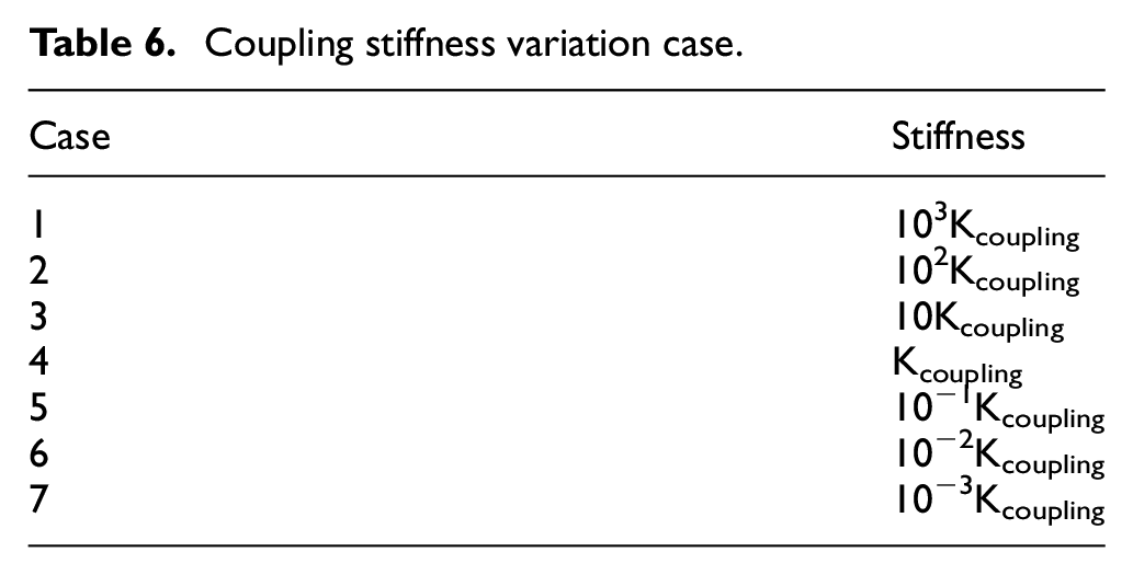
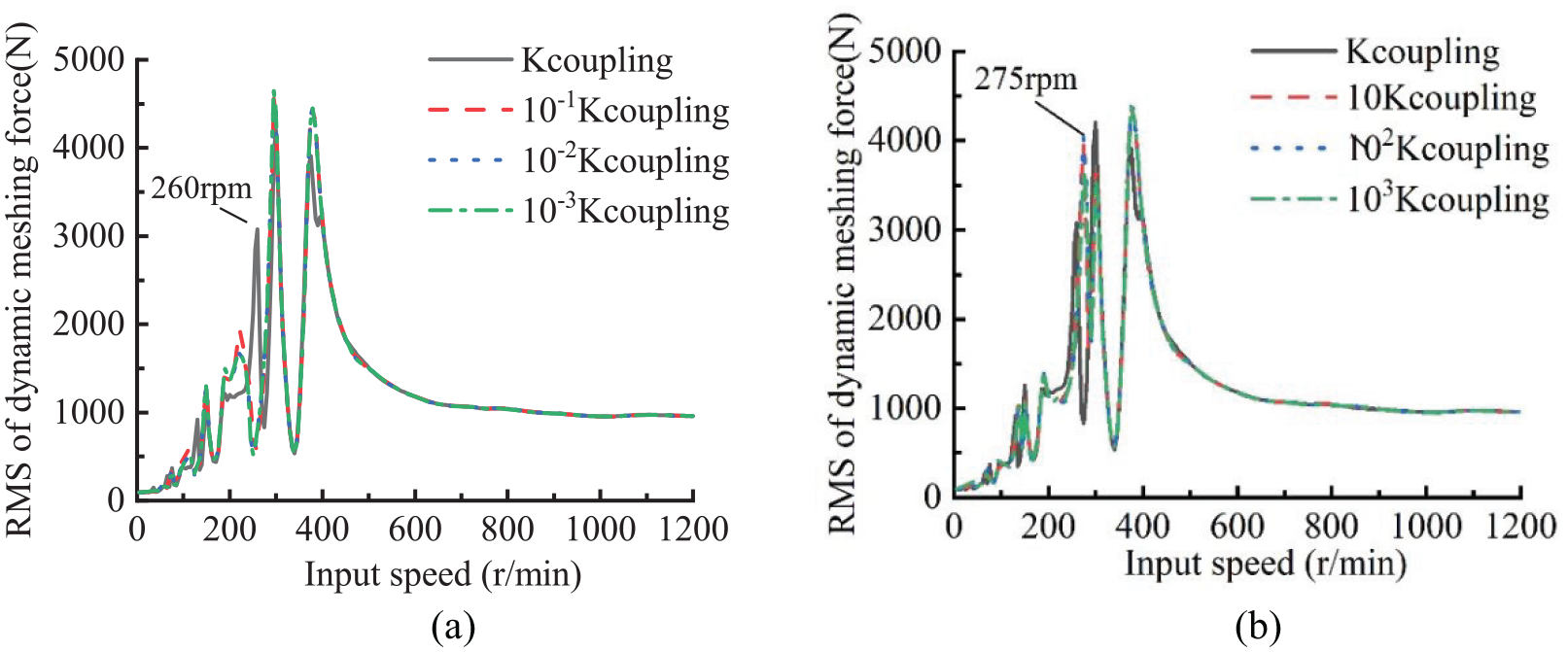
Figure 18 shows the RMS curve of the dynamic meshing force of the No.1 meshing element under different coupling stiffnesses. It is observed that the resonance peaks of 385, 260, 115, and 35 rpm due to coupled under 10−1Kcoupling∼10−3Kcoupling disappear. At 385 rpm, the 253rd order natural frequency of 10−1Kcoupling∼10−3Kcoupling and the 242nd order natural frequency of 10Kcoupling∼103Kcoupling are 833 Hz, but shaft1and shaft2 have no motions, so the dynamic meshing force RMS curve does not produce resonance peak. At 260, 115, and 35 rpm, shaft1 and shaft2 of GB1 also have no motions, so there are no resonance peaks.

RMS of dynamic meshing force of No.1 meshing element under different coupling stiffness: (a) RMS of meshing force of No.1 meshing element under Kcoupling~10−3Kcoupling and (b) RMS of meshing force of No.1 meshing element under Kcoupling~103Kcoupling.
Under 10Kcoupling∼103Kcoupling, the 385 rpm resonance peak of the meshing force RMS curve of the No.1 meshing element disappeared, but a larger resonance peak was produced at 280 rpm. At this time, 10Kcoupling∼103Kcoupling corresponds to the natural frequency of 599.7524 Hz at the 202nd order of the system, and the shaft2 of GB1 and shaft3 of GB2 have bending-torsional coupled motions, as shown in Figure 19. From the meshing force spectrum of No.1 meshing element under Kcoupling∼103Kcoupling, it is found that with the increase of stiffness of couplings, the maximum amplitude of fm2 in the spectrum increases, and the corresponding speed changes, as shown in Figure 20.

Mode shapes of shaft2 and shaft3 of the 202th order at 103Kcoupling: (a) shaft 2 mode shape and (b) shaft 3 mode shape.
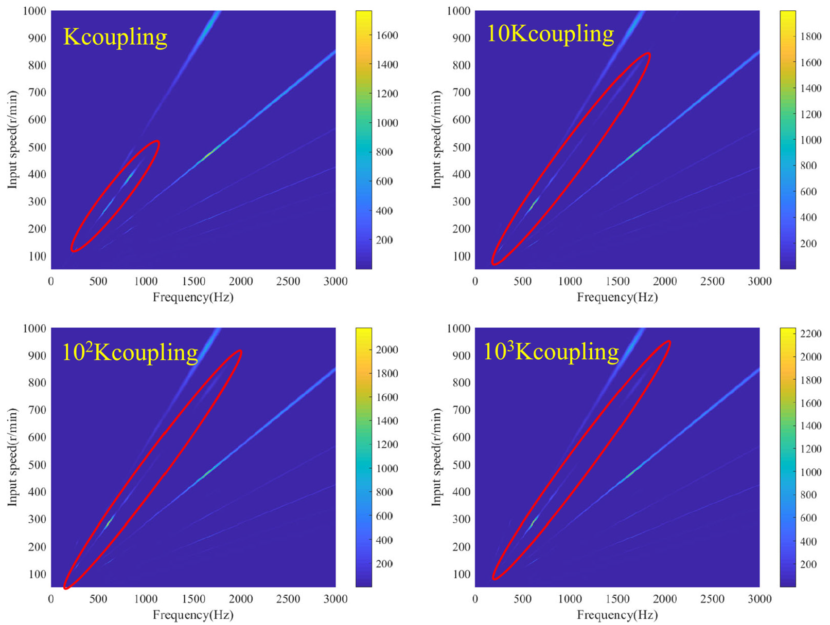
The meshing force spectrogram of No.1 meshing element under Kcoupling~103Kcoupling.
In Figure 21, for the No.3 meshing element, the resonance peak at 260 rpm generated by the coupled disappears under 10−1Kcoupling∼10−3Kcoupling. A resonance peak with a larger amplitude was produced at 275 rpm under 10Kcoupling∼103Kcoupling. In Figure 22, for the No.7 meshing element, the resonance peak amplitude decreases under 10−1Kcoupling∼10−3Kcoupling. New resonance peaks are generated at 95 and 115 rpm under 10Kcoupling∼103Kcoupling. Figure 23 shows the spectrogram of meshing force of No.7 meshing element under Kcoupling∼10−3Kcoupling. It can be seen that the amplitude of fm3 caused by coupled decreases with the decrease of stiffness of couplings. For the No.1 meshing element and No.7 meshing element, which are greatly influenced by coupled effect, they are more sensitive to the change of stiffness of couplings. When the stiffness of coupling decreases, the coupling effect weakens, on the contrary, the coupling effect increases. For GB3, which is not affected by the coupled effect, the RMS curve of meshing force under different coupling stiffness does not change significantly, as shown in Figure 24.
RMS of dynamic meshing force of No.3 meshing element under different coupling stiffness: (a) RMS of meshing force of No.3 meshing element under Kcoupling~10−3Kcoupling and (b) RMS of meshing force of No.3 meshing element under Kcoupling~103Kcoupling.
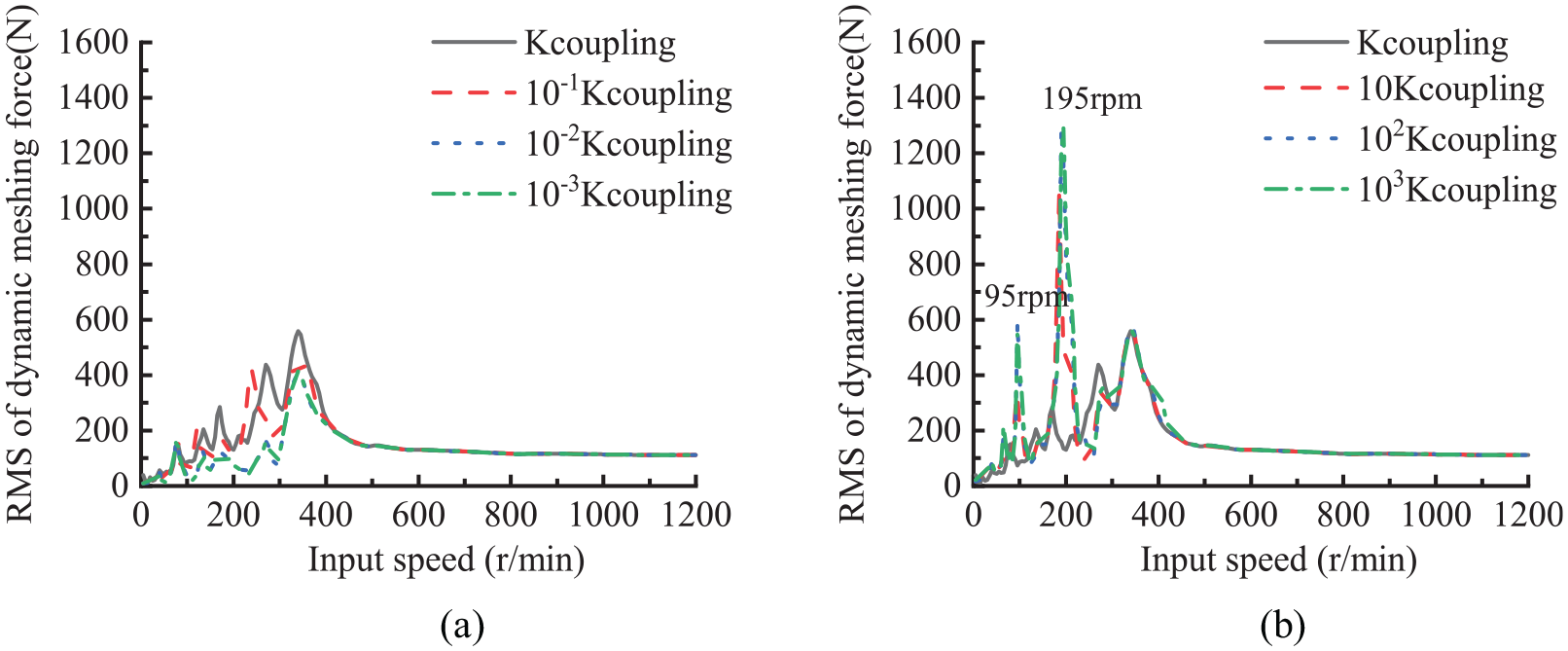
RMS of dynamic meshing force of No.7 meshing element under different coupling stiffness: (a) RMS of meshing force of No.7 meshing element under Kcoupling~10−3Kcoupling and (b) RMS of meshing force of No.7 meshing element under Kcoupling~103Kcoupling.

The meshing force spectrogram of No.7 meshing element under Kcoupling~10−3Kcoupling.

RMS of dynamic meshing force of No.9 meshing element under different coupling stiffness: (a) RMS of meshing force of No.9 meshing element under Kcoupling~10−3Kcoupling and (b) RMS of meshing force of No.9 meshing element under Kcoupling~103Kcoupling.
According to analysis and comparison, gear pairs which are greatly affected by coupled are sensitive to the change of the stiffness of couplings. Reducing the stiffness of the couplings can make the resonance peak of the RMS curve of the meshing force generated by the coupled disappear or the amplitude will be reduced, and the coupled effect will be weakened. Increasing the stiffness of the coupling will produce a resonance peak with a larger amplitude and increase the coupled effect. With the coupling stiffness increasing, new modes are generated. When the excitation frequency is close to the new mode, a large dynamic response occurs. Therefore, the influence of the stiffness change of the multi-gearbox system on the dynamic characteristics mainly affects the system modal, which in turn affects the dynamic response of the system.
Influence of supporting stiffness
The housing is an important supporting component of the marine multi-gearbox transmission system. To analyze the influence of the housing on the vibration response of the multi-gearbox coupling system, the dynamic meshing force and bearing reaction force in the system were investigated under four housing stiffness cases. As shown in Table 7, the four cases are without housing, Khousing, 103Khousing and 10−3Khousing respectively.
Cases of different housing stiffness.

Figure 25 shows the RMS of the dynamic meshing force curve of the No.1 meshing element. It changes little under the four cases, indicating that the housing has little influence on the meshing force in the multi-gearbox transmission system. This conclusion is consistent with the influence of the housing on the system in a single gearbox. 18 It can be seen that the resonance peaks of 385 and 260 rpm caused by the coupled of multiple gearboxes have not changed, indicating that the stiffness of the housing has little influence on the coupled effect of the multi-gearbox system. The meshing force is not sensitive to the change of the stiffness of the housing mainly because it has little influence on the gear rotor mode in the system. It can be seen from the results that the resonance peak of the dynamic meshing force RMS curve does not change under several housing stiffnesses. It indicates that the mode of the gear-rotor system does not change with the change of the stiffness of the housing.

RMS of dynamic meshing force of No.1 meshing element under four cases.
There are many bearings in the system. In this section, taking No.4 bearing in GB1 as an example, the influence of housing stiffness on bearing reaction force is analyzed. Figure 26 shows the RMS curve of the bearing reaction force of No.4 under the four cases. It can be seen that the influence of the housing stiffness on the bearing reaction force is mainly in the low-speed stage, and the curve does not change significantly after 315 rpm. In Figure 26(a), the RMS curve of the bearing reaction force after coupled the housing produces a new resonance peak at 90 rpm. It indicates that the coupled housing will generate new modes of the system. As shown in Figure 26(b) and (c), the RMS curves of the bearing support reaction forces of without housing and 103Khousing completely coincide, and the 90 rpm resonance peak generated by the coupled housing disappears under 103Khousing. This means that when the housing stiffness is very rigid, the influence of the housing can be ignored in the prediction of the system’s dynamic characteristics. The resonance peak before 200 rpm changes significantly when the housing stiffness is reduced, As shown in Figure 26(d). The bearing reaction force is more sensitive to the change of the housing stiffness mainly because the bearing is installed on the housing. In the dynamic model, the bearing-housing element is coupled with the housing-foundation element, and the change of the housing stiffness will change the support stiffness, which in turn affects the bearing reaction force.

RMS of bearing reaction force of No.4 bearing-housing element under four cases: (a) Khousing and without housing, (b) without housing and 103Khousing, (c) 103Khousing and Khousing, and (d) Khousing and 103Khousing.
Conclusion
To study the coupled dynamics characteristics of the marine multi-gearbox system, a multi-gearbox coupled model was established by using the finite element theory and substructure technique. In addition, three corresponding dynamic models of single gearboxes are established for comparison. In this paper, the natural frequency and the RMS of meshing force of multi-gearbox system and single gearbox are analyzed. And the dynamic response of the multi-gearbox system under different stiffness of coupling and housing. The main conclusion are summarized as follows:
It is found that the adjacent gear pairs of adjacent gearboxes are more easily affected by the coupled effect. The coupled of multiple gearboxes will make the system generate new modes. The RMS curve of meshing force produces some new resonance peaks, which are caused by the new modes excited by the mesh frequencies of adjacent gearboxes. At this time, the mesh frequency components of adjacent gearboxes account for a large proportion of the response spectrum.
Reducing the stiffness of the coupling can make the resonance peak of the RMS curve of the meshing force generated by the coupled disappear or the amplitude will be reduced, and the coupled effect will be weakened. Increasing the stiffness of the coupling will produce a resonance peak with a larger amplitude and increase the coupled effect. Gear pairs which are greatly affected by coupled are sensitive to the change of the stiffness of couplings.
The influence of the housing on the dynamic response of the system is mainly concentrated in the low-speed stage. Housing has a more significant influence on the bearing support force. When the housing is very rigid, the model can ignore it and reduce the calculation amount. On the contrary, it should be considered in the model.
Footnotes
Appendix
Handling Editor: Chenhui Liang
Declaration of conflicting interests
The author(s) declared no potential conflicts of interest with respect to the research, authorship, and/or publication of this article.
Funding
The author(s) disclosed receipt of the following financial support for the research, authorship, and/or publication of this article: This research is supported by National Key R&D Program of China (Grant No.2018YFB2001501), the Key Program of National Natural Science Foundation of China (Grant No.51535009), and National Natural Science Foundation of China (Grant No.52005382).