
Abstract
A bucket structure optimization method based on compound digging trajectory and limit digging force was proposed for the problem that the real digging resistance of excavators is difficult to measure and difficult to use as bucket load for structure optimization. The uncertainty of the digging resistance in the actual digging process of the excavator was analyzed, and a digging trajectory was obtained by active digging using the compound digging action. Based on the limit digging force model, the digging force and its variation law were calculated, and analyzed for different hydraulic cylinder’s active digging in the trajectory. Based on the bucket shape line equation, a parametric model of the bucket was established using APDL language, and the bucket stress variation under different digging actions was analyzed. The bucket stress and mass were reduced by 4.59% and 5.84% respectively after optimization.
Keywords
Introduction
As an important member of construction machinery, hydraulic excavators have received a lot of attention from researchers. Šalinić et al. 1 established kinematic and kinetic equations for the working device of hydraulic excavator based on soil mechanics and Kane’s equation. Mitrev et al. 2 established a kinetic equation containing an open kinematic chain and a closed-loop. Vujic et al. 3 established a kinematic model with a maximum of five degrees of freedom. Zhu et al. 4 derived an expression for the variation of digging resistance with time under sinusoidal excitation. Huang and He 5 measured the effect of different vibration digging parameters on the vibration digging resistance. Lv and Jihong 6 derived a method for calculating the theoretical digging force of a hydraulic cylinder and calculated the maximum actual digging force of a bucket digging. Chen et al. 7 proposed an optimization method of maximum excavation force and average excavation force based on mining trajectory. Wu et al. 8 proposed a prediction method of excavation force. Koizumi et al. 9 proposed a method to optimize the efficiency of the excavator based on the excavation trajectory and excavation speed. Yoshida et al.10,11 developed a kinetic model based on the Newton-Euler equation containing a closed-loop to increase the soil mass in the bucket and reduce the energy consumption of excavation by optimizing the excavation trajectory. Kim et al. 12 and Li et al. 13 proposed a method to calculate the theoretical excavation force of the hydraulic cylinder and to calculate the maximum actual excavation force of the bucket. Zou et al.14,15 established the dynamic relationship between the digging force of the bucket and the thrust of the hydraulic cylinder, and proposed a dynamic trajectory planning method based on the integration of soil-shovel interaction. Fujino et al. 16 investigated the relationship between the digging load and the bucket strain. Hu et al. 17 used the thickness of the arm steel plate as the design variable to optimize the weight of the arm. Xu et al. 18 optimized the bucket based on the equal strength design theory. Xu et al. 19 used a multi-objective evolutionary algorithm to optimize the amount of bucket cutting angle change, the maximum rod digging force, and the maximum bucket digging force. Yu et al. 20 proposed a lightweight optimization method for the bucket under uncertain loads. Zhang et al. 21 made a study of the bucket mechanism. Lu et al. 22 optimized the bucket structure parameters based on the digging resistance under different working conditions.
In summary, researchers have focused on the optimization of the overall kinematics and dynamics of the hydraulic excavator work unit or the structure of certain mechanisms, while the uncertainty of the digging resistance of the bucket as a part of the excavator in direct contact with the soil makes its structural strength more difficult to analyze, resulting in less relevant research/result on the optimization of the bucket structure under real loads.
Previously, the author’s team has carried out some studies on bucket optimization from a theoretical view, which will be briefly presented in Section 3. The present study differs in that it optimizes the bucket in terms of strength based on the literature 25 and under real working conditions. This research proposes a method for optimizing the bucket structure based on a compound digging trajectory and limit digging force.
Optimization method and selection of digging trajectory
Bucket structure optimization method
For construction machinery with different movement states and complex and variable working objects such as excavators, the operation process is subject to the joint action of various loads such as tension, impact, and torsion, and the digging resistance is complex and variable, making it difficult to obtain accurate results. At the same time, in the real working environment, the soil as the excavator’s working object, it’s internal contains many uncertain factors, such as large volume of stones, sticky sediment, etc., can not get the real digging resistance of the specific change law. Different digging movements produce different excavation trajectories, the excavator will encounter complex excavation resistance in different trajectories. As a result, there is uncertainty in the digging resistance, which also creates difficulties in optimizing the structure of the excavator bucket. To solve this problem, the authors’ team proposed a bucket structure optimization method based on compound digging trajectories and limit digging force, which is based on the following process (Figure 1).

Optimization process of the bucket structure.
Selection of the digging trajectory
In the actual digging process, the digging trajectory which is closely related to the working performance of the excavator is determined by the relative angle of the rod and bucket together. The structure diagram of the working device of the excavator is shown in Figure 2(a). Taking the working device of the excavator and the hinge point of the car body as the origin, the front of the working device as the Y-axis and the upper part of the working device as the Z-axis. The vertical direction with the whole working device as the X-axis, the X-axis is perpendicular to the YZ plane, and to the picture outwards. The action of changing the angle between the body and the arm θ1, the angle between the arm and rod θ2, and the angle between the rod and bucket θ3 at the same time is the compound digging action, which is the real, common digging action of the operator. The main digging area of the excavator is below the ground and the influence of the main digging area on the digging performance is considered at the beginning of the excavator design, therefore, the digging trajectory in the main digging area is chosen as the premise of the study. A compound digging trajectory was obtained through the compound digging action of excavator, 23 this trajectory is shown in Figure 2(b), the corresponding tooling clamp angle variation of this trajectory is shown in Figure 3.

Excavator working device and digging trajectory: (a) structure of the excavator working device, (b) compound digging trajectory.
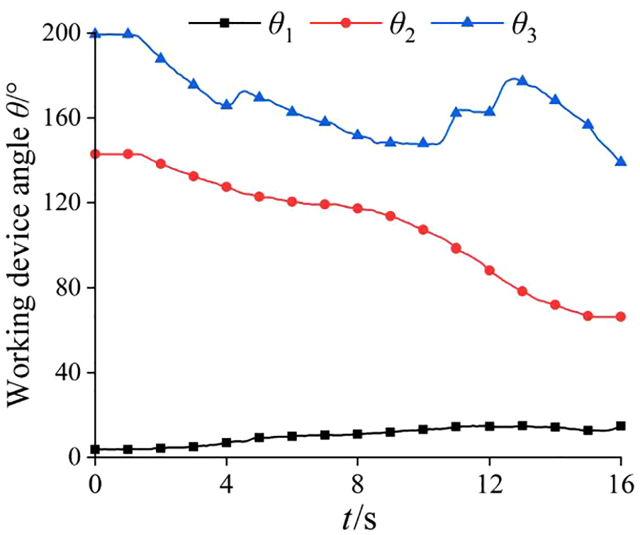
Variation of tooling clamping angles.
In Figure 3, the X-axis is the time, which is the time it takes for the bucket tooth tip to move from point D to D′, and complete the compound digging trajectory shown in Figure 2(b).
Limit digging force
Excavation force and digging resistance are a pair of interacting forces. The maximum digging resistance of the bucket of a hydraulic excavator in the actual digging process is the maximum digging force that the excavator can exert in the actual working process, therefore, the maximum digging force that the excavator can exert is calculated, and the maximum digging resistance, that is, the dynamic load of the excavator, is also found.
Based on the principle of the synthesis of the excavation resistance system toward the cutting edge, the authors’ team 24 proposed a limit digging force model that considers tangential forces, normal forces, and moments simultaneously. The actual excavation process will face different hardness of the work object, the bucket, rod hydraulic cylinder in which play different roles, when the work object hardness is high, due to the reduction of the cutting thickness, to fill the bucket, using the rod hydraulic cylinder to dig, the above excavation force model also fully consider the different hydraulic cylinder active digging situation. Figure 4 shows the maximum digging force that can be exerted by the excavator when the bucket tooth tip is at a certain digging point in the compound digging trajectory, and the bucket hydraulic cylinder and rod hydraulic cylinder are used for digging operations respectively, that is, the limit digging force at that digging point.

Limit digging force for a given digging trajectory: (a) bucket hydraulic cylinder, (b) rod hydraulic cylinder.
As shown above, the maximum combined digging force of the bucket hydraulic cylinder is 172.946 kN, with a tangential force of 160.546 kN and a normal force of −64.231 kN; the maximum combined digging force of the rod hydraulic cylinder is 115.057 kN, with a tangential force of 113.784 kN and a normal force of −17.068 kN. In the limit digging force model, although the same tangential force is used as the ratio of the normal force Fn to the tangential force Ft varies within a certain range, although the same independent variables are used. The coefficients have positive and negative values, resulting in a change in direction of the normal force, that is, there are positive and negative values of the normal force. The maximum digging forces of the bucket and rod cylinders occur at approximately the same time, and the peak digging force is significantly greater than that of the rod cylinder when the bucket cylinder is used to complete this section of the trajectory.
Parametric modeling of the bucket
The bucket, as the executive end of the hydraulic excavator, has an important influence on the excavation process, with the cutting edge plate, the front wall plate, the bottom arc plate, and the rear wall plate being the main factors in determining the shape of the bucket structure. As shown in Figure 5, the symmetry plane of the bucket is used as the cross-section, and the cross-section lines of the front wall plate, bottom arc plate, and rear wall plate on the inside of the bucket are the front wall line l1, bottom arc line l2, rear wall line l3, and the three cross-section lines form a continuous curve. The shape of the bucket in its plane of symmetry is mainly determined by this curve, which is called the bucket shape line, and the bucket length line l4 is used to connect the bucket shape line at the beginning and end to form a closed curve. 25 To express the geometry of the bucket-shaped line, the center of the circle of the bucket bottom arc is the origin O, the horizontal direction of the bucket length line is the X-axis, the direction passing through the origin O and perpendicular to the X-axis is the Y-axis, and the direction perpendicular to the XY plane to the outside of the picture is the Z-axis, to establish a right-angle coordinate system. As can be seen from the picture, the bucket shape line is determined by the cutting angle β, the bucket length R, the bucket back angle γ, and the radius r of the bucket base plate.

Geometric model of the bucket shape line.
The geometric relationship between the form line and the bucket capacity q leads to the mathematical expressions for the form line and the cross-sectional perimeter L, the cross-sectional area S, and the bucket width W, as shown in the following equation.


The parameters required for the parametric modeling of the bucket can be calculated using the above equations and substituted into the parametric model building process of the bucket. On the premise of retaining the main structural and dimensional features of the original bucket, details that have little or no effect on the finite element calculation results, 26 such as the reinforcement plate at the bottom of the bucket, the shape of the trunnion plate, the presence or absence of bucket teeth, etc., need to be ignored to ensure the smooth division of the mesh. The bucket material was set to E355DD and the bucket mass was found to be 569.482 kg after the modeling was completed (Figure 6).

Bucket after parametric modeling.
Full restraint is applied to the bucket at the hinge point with the rod. When applying loads to the bucket, the tangential resistance, normal resistance, and resisting moment of the limit digging resistance in each section of the trajectory are used as external loads respectively. To prevent excessive calculation errors due to stress concentrations, the concentrated forces applied are converted into component forces distributed over multiple nodes loaded on multiple nodes of the bucket teeth. 27 Using the digging resistance in Section 2 as the bucket load, the bucket stress and deformation in each section of the trajectory can be obtained with time by simulation, as shown in Figure 7. The cloud diagram of the stress distribution at the time of maximum stress in the bucket is shown in Figure 8.

Bucket stress under digging with different hydraulic cylinders.

Maximum stress cloud of the bucket.
Optimization of the bucket structure
Optimization objectives
Optimization of the overall bucket structure is a three-dimensional optimization, involving specific digging conditions. Whether the maximum bucket stress is less than the material yield strength has a great influence on the efficiency of the excavator. Optimization presupposes no change in bucket capacity, the maximum stress of the bucket is taken as the optimization objective 1. When the excavator plays a constant digging force and cuts the same volume of material, the smaller the total mass of the bucket, the more the production cost can be saved, and since all materials of the bucket are set to E355DD with the same density, the mass is taken as the optimization objective 2. This results in the following multi-objective optimization function for the bucket structure.

Design variables
The structural parameters such as the cutting angle β of the bucket, the radius r of the bucket bottom arc, the rear angle γ of the bucket, and the bucket length R were selected as design variables, that is,

Constraint conditions
Base constraints
0.9 and 1.1 times the values of the cutting angle β, bucket length R, bucket back angle γ, and bucket base radius r in the original bucket were selected as the optimization interval, as shown in Table 1.
Value range of bucket parameters.

Performance constraint 1
The amount of change in bucket mass is substituted into the structural optimization as a performance constraint. After optimization, the amount of change in bucket mass should be greater than 5% and the constraint is expressed in the following equation.

Performance constraint 2
The maximum stress of the bucket is substituted into the structural optimization as performance constraint 2. The maximum stress after optimization should be less than before optimization and the constraint is expressed in the following equation.

Optimization results
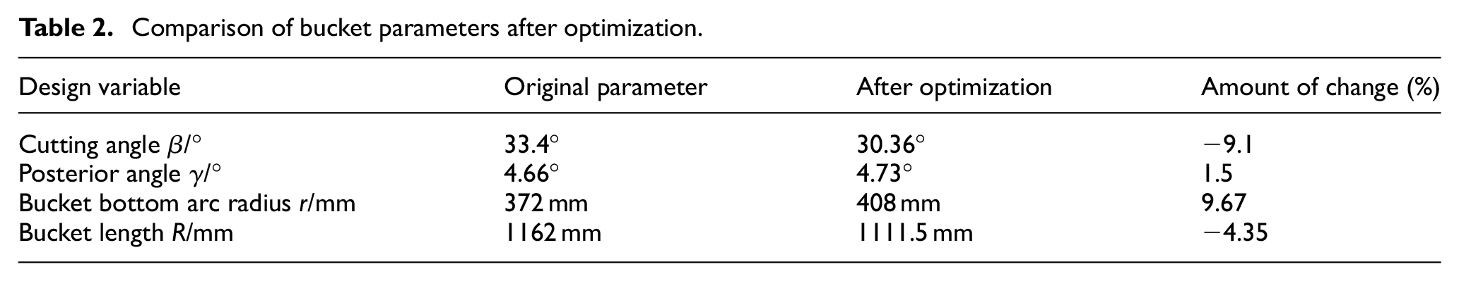
The method used for this optimization is a genetic algorithm. The details of the bucket structure optimization are: (1) write a formula for calculating the bucket mass and input it into the MATLAB genetic algorithm toolbox; (2) set a range of parameter values; (3) write a constraint procedure; (4) solve for the result that meets the mass constraint; (5) call the APDL procedure and compare whether this result meets the stress constraint; (6) if it does, the optimization is complete; if not, the bucket structure parameters are selected again and step (1) is repeated until the desired result is obtained. After optimization, the comparative results of the bucket structure parameters, optimization evaluation index, and maximum stress are shown in Tables 2 and 3, and Figure 9 respectively.
Comparison of bucket parameters after optimization.
Comparison of bucket evaluation indexes after optimization.


Optimized bucket stress.
As can be seen from Table 2, the cutting angle β is reduced by 9.1%, the bucket back angle γ increases by 1.5%, the radius of the bucket base arc r increases by 9.67%, and the bucket length R decreases by 4.35% for the four design variables; as can be seen from Table 3, the maximum stress σ is reduced by 4.59%, the mass M is reduced by 5.84%, and the optimization target f is reduced by 5.54%.
Conclusions
Based on the hydraulic cylinder active digging method and the limit digging force model, the digging force of different hydraulic cylinder active digging in the compound digging trajectory was calculated and analyzed. A parametric model of the bucket was established using the bucket shape line mathematical equation and APDL language. The limit digging force was used as the external load to analyze the change of bucket stress in the composite digging trajectory.
The maximum digging point was selected as the premise of the optimization, the bucket mass and maximum stress were reduced as the optimization objective, and several bucket structure parameters were selected as design variables and optimized using genetic algorithms.
Footnotes
Acknowledgements
The authors greatly appreciate the reviewers’ suggestions and the editor’s encouragement.
Handling Editor: Chenhui Liang
Declaration of conflicting interests
The author(s) declared no potential conflicts of interest with respect to the research, authorship, and/or publication of this article.
Funding
The author(s) disclosed receipt of the following financial support for the research, authorship, and/or publication of this article: This work was funded by the National Natural Science Foundation of China (No. 51605270), the Natural Science Research Project of Shaanxi Province (No. 2020JM-600), the Shaanxi Provincial Department of Education Scientific Research Project (No. 19JK0172), and Shaanxi Provincial Science and Technology Department Key R&D Program Project (No. 2019TSLGY02-03).
Data availability
All data included in this study are shown in the relevant figures and tables in the article.