
Abstract
In this work, we have studied the performance of the cooling system with the presence of graphene oxide (GO) and molybdenum sulfide (MoS2) nanoparticles to reduce heat stress, increase the final efficiency, and maintain the reliability of Diode and IGBT electronic module. Beyond the geometric design of micro-sprays and dimensional changes, as well as the type of cooling fluid effect, the use of nanofluids for the purpose of thermal management of electronic systems will be an interesting and effective innovation. In the simulation parameters, the dimensional ratio of micro-sprays, the rate of cooling flows, and the volume fraction of nanoparticles were investigated. According to the results, considering the spray of the BSM-4N model and the input mass rate of 0.04 kg/s, by increasing the volume fraction of nanoparticles from 0.01 to 0.05, the heat transfer of nanofluid increases, thus leading to an increase in thermal efficiency. In this paper, the thermal effects of GO nanoparticle were significantly more favorable than those of MoS2 nanoparticle. In addition, it was found that by reducing the spray nozzle using installing the blade and simultaneous use of GO nanofluid with volume fraction of 0.05, the temperature inside the module is reduced below 323 K.
Introduction
Nowadays microprocessors are the main component of electronic devices. Microprocessors in particular have increased the speed of electronic systems and increased daily usability.1,2 Using high-powered systems and applications such as transistors,3,4 IGBT, 5 and inverters 6 require more thermal management. The main needs in the field of cooling and heat management that must be addressed are the limited space of the devices, high heat flux, and prevention of high pressure drop. However, thermal management in the design and production of IGBTs is one of the main issues in the evaluation of modern components and systems. In recent years, the use of heat micro-channel sinks and heat transfer in micro-scale surfaces has been very popular.7,8 Heat sinks have a variety of applications in the field of electronics for the purpose of cooling the most advanced systems. 9 Due to their small size and delicate construction, micro heatsinks are capable to reduce temperature and reduce heat loss in a short period of time.
In fact, micro heatsinks can be divided into two categories: traditional and manifold.10,11 Traditional micro heatsinks have disadvantages such as high pressure drop and undesirable thermal changes.12,13 Therefore, the use of manifold heatsinks is more common due to their smaller dimensions, which are able to make the thermal boundary layer thinner and prevent high pressure drop. 14 However, the electronics industry has made amazing progress, so a broad perspective must be considered in this regard. 15 Undoubtedly, advances in cooling play a key role in maintaining the real life of the electronic components and components of high-powered systems. Using the new idea of jetting fluid through a spray can be an interesting way to reduce heat and maintain and increase the reliability of the device and increase the efficiency of the electronic system. In fact, jetting causes the thermal boundary layer and the thermal resistance of the devices to decrease, and due to the satisfactory heat transfer, it causes cooling and increases the life of electronic components and systems.16,17 Additionally, the use of additive materials can increase some characteristics of base materials.18–20 Choi and Eastman (in 1995) for the first time introduced nanofluids as a way to improve heat transfer rate. 21 Nanofluids are also a major component in the cooling of electronic components today. In fact, selecting the appropriate nanofluid in heatsinks can be another suitable solution to reduce the temperature peak of electrical components.8,22
Greco et al. 23 have investigated the dimensional effects of nozzles on the cooling of hot surfaces of electronic components. Markal 24 investigated the experimental work of spraying the working coolant in rotation to reduce the heat. His results show that by increasing the Reynolds values, his innovative work has favorable thermal effects compared to previous work. Ahmed et al. 25 have simulated and compared spraying fluid with and without rotation in a simple microchannel. They found that shrinking the nozzle end of the Reynolds 35,000 would result in better thermal management performance of the cooling device. Nakarintr et al. 26 in their study of heatsinks and cooling by fluid spraying found that with increasing mass flow rate, the average Nusselt amount, and pressure drop increase. In another paper, Zang et al. 27 numerically studied the effect of fluid spraying to reduce heat loss in the mini-channel with the barrier. They found that using horizontally designed barriers further reduced the temperature gradient and created greater temperature uniformity compared to a simple rectangular barrier. Timah et al. 28 have conducted an experimental and theoretical study in the field of cooling using nanofluids on a flat horizontal surface. They found that by increasing the volume fraction of aluminum oxide and copper oxide nanoparticles at Reynolds 24,000, the average Nusselt increased so that the copper oxide exhibited higher thermal effects. Hossein et al. 29 investigated the spraying of fluid in microchannel heatsinks with column nozzles. Their results indicate that the simultaneous use of column jets for cooling and micro-channel barriers reduces the pressure drop to a desirable level. Purusothaman 30 investigated the natural convection heat transfer in an electronic module using Cu-H2O nanofluid. The output of this paper shows that the effect of nanofluid on the Nusselt amount increases with increasing Darcy number. In another simulation, Paniagua-Guerra et al. 31 designed micro-jets with special fractals to increase thermal efficiency. Their results show that increasing the number of channels from 16 to 64 leads to a decrease in the thermal resistance of the parts. Beyond this, they stated that the 64-house micro-channel model has a higher pressure drop compared to the 16-house micro-channel. Pourfattah et al. 32 investigated the cooling of two-phase current in comb heatsinks with copper oxide nanofluids with different volume fractions. The results show that by increasing the ratio of the length of the inlet to the length of the outlet, the amount of local Nusselt increases. Some recent studies of micro-sprayer, nanofluid, and other active and inactive methods for improving the thermal performance of a micro-heatsink are listed in Table 1.
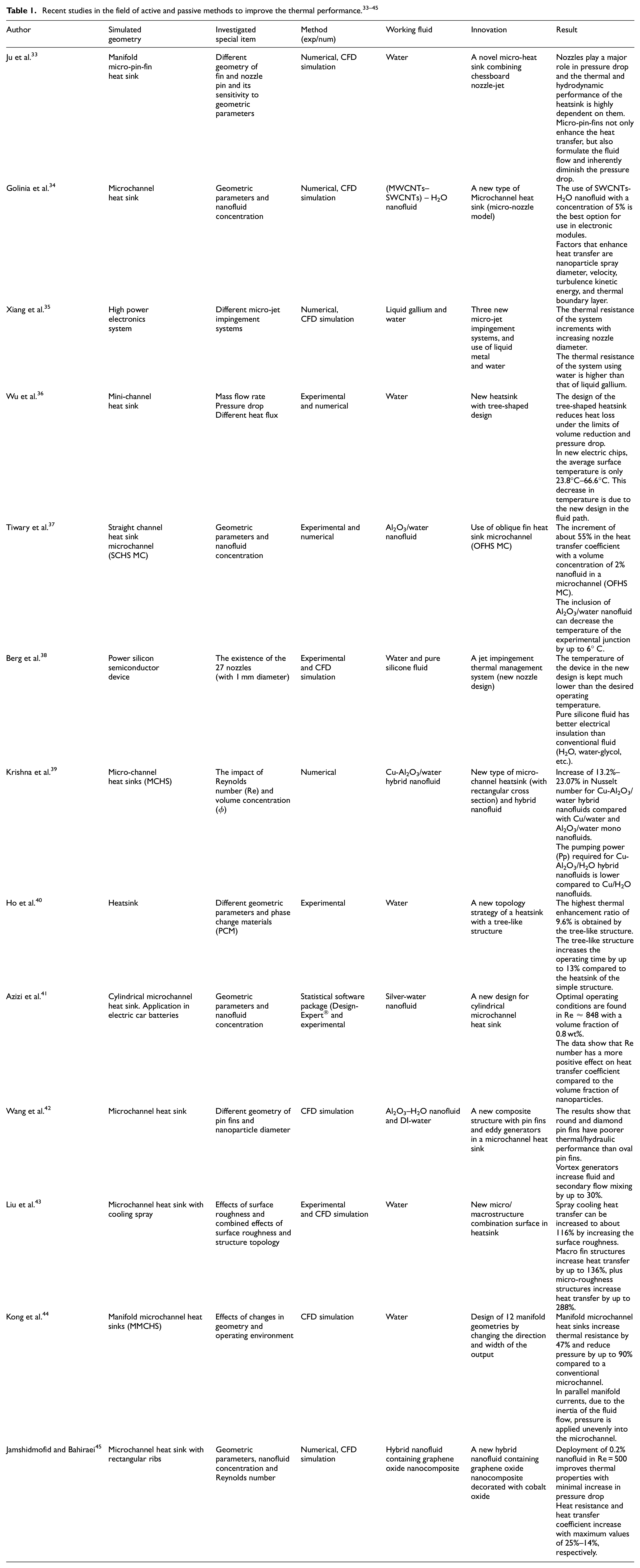
According to the studies in Table 1 among the methods used to increase the heat transfer rate, the use of (GO-MoS2)/H2O nanofluids and a new micro-sprayer model to increase the efficiency of the power electronic module has not been done simultaneously. Hence, the main purpose of this article is to fill this scientific gap. In fact, we investigated thermal management and temperature uniformity inside an electronic device. The present simulation evaluates the heat transfer for the purpose of cooling an electronic system (Si-IGBT) by examining parameters including: spray size ratio (with different blades) and volume fraction of nanofluids (graphene oxide (GO), molybdenum sulfide (MoS2)), etc. This work is measured and evaluated using ANSYS-FLUENT numerical software with a new idea (blade spray) as a structural and fluid coupling. In order to ensure the results, this article has been compared to similar previous works and after validation, we have performed computer simulation.
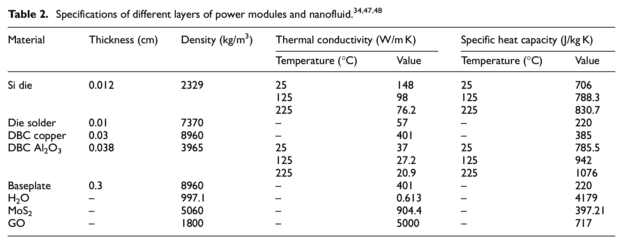
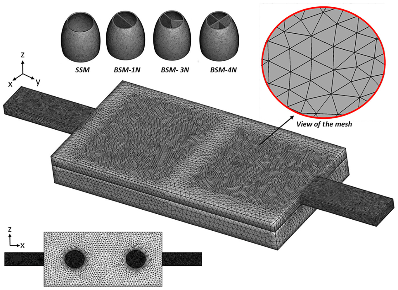
Problem description
This paper investigates the stable 3D simulation of a power module using nozzles to launch a cooling nanofluid (H2O-GO and H2O-MoS2). The selected power module includes base plate, Heater, IGBT, Diode, DBC, and solder. 34 Figure 1 shows an overview of the cooling path and sprays. According to this shape, Four types of sprays are used: simple spray model (SSM), one-blade spray model (BSM-1N), three-blade spray model (BSM-3N), and four-blade spray model (BSM-4N). The physical characteristics of electrical components and nanofluids are given in Table 2. In this paper, heating operations under three heat fluxes 100, 180, 250 W/cm2 to the IGBT section and three heat fluxes 100, 150, 180 W/cm2 to the Diode section has been done. Nanofluid for cooling electrical devices enters from the bottom of the device and exits through side channels. In order to spray the nanofluids, channels are installed in the lower part of the diode and IGBT, which is soldered, through which the cooling fluids are released after cooling. 34 It is worth mentioning that in this work, simulation of different volume fractions of nanofluids was also evaluated.
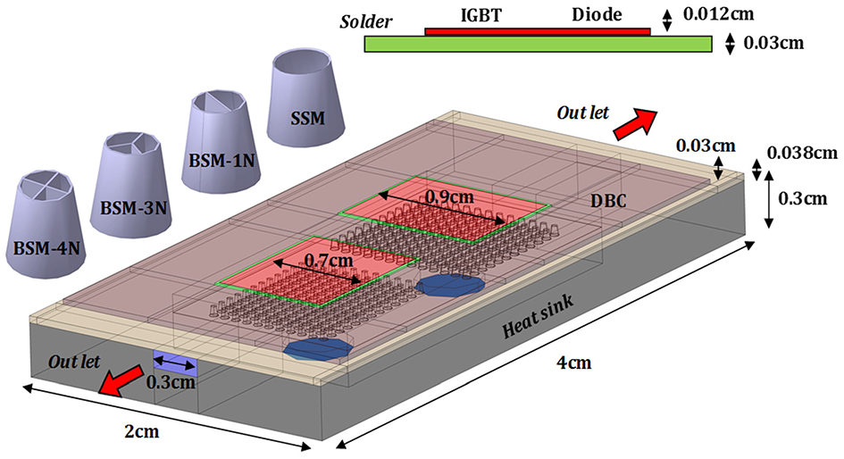
Schematic of an electronic module.
The governing equations (nanofluid)
The governing equations have been used under stable conditions. Based on the objectives of the paper, the governing equations are: continuity, momentum, and energy. In the presented work, the K-epsilon model is used to model the turbulence flow. The equations and terms that affect the problem are given below 46 :


The stress tensor is defined in the following form:

Applying nanoparticles in a fluid undoubtedly changes the physical properties of materials. In order to calculate the physical properties of the nanofluids used in the problem, the following equations can be used47,48:
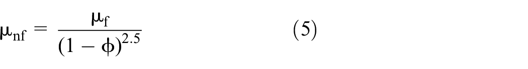


Where (
Here our definition of pressure changes is the difference between the inlet pressure and the outlet of the module internal channel. We calculate the pumping power by multiplying the velocity inlet (

And the system performance coefficient can be calculated using the following formula 34 :
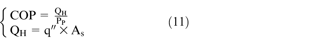
Where
Grid independence
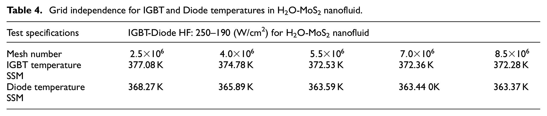
The mesh used in this simulation (triangular mesh) is shown in Figure 2. Tables 3 and 4 show the number of meshes and how to select them in two different modes. The maximum number of selected networks for the whole computing area in the form of SSM is about 8,500,000 cells, which is obtained in terms of heat flux of 250 W/cm2 in the IGBT section and 190 W/cm2 in the Diode section. However, 5,500,000 cells have been selected for various tests because more than 5,500,000 network numbers not only do not affect the modeling results, but also extend the solution process in terms of time. Similarly, at a heat flux of 100 W/cm2 in the IGBT section and 100 W/cm2 in the Diode section, 5,420,000 cells were selected. In general, the largest number of selected networks is related to the geometry of BSM-4N, which is about 12,670,000. A system with a 32-core processor and 64 RAM is used for simulation. The main steps of this research are shown in Figure 3.
Schematic of the computational network from fluid duct.
Grid independence for IGBT and Diode temperatures in H2O-GO nanofluid.

Grid independence for IGBT and Diode temperatures in H2O-MoS2 nanofluid.

The structure of the present project.
Results and discussion
Due to the special shape of the channel, the behavior of the fluid has a high pressure and velocity gradient and the creation of vortices leads to turbulent behavior in the fluid. Therefore, in this numerical work, we have used the K-epsilon turbulence model in order to have higher simulation accuracy. In this article, we have evaluated the two previous simulation works50,51 with the aim of validating them in order to gain sufficient confidence about the quality of the presented simulation work. Fortunately, validation has resulted in an ideal match with the intended work (See Figure 4).

Figure 5 shows how heat fluctuations affect the temperature of the study environment. In this study, we used a comparison of the cooling parameters of graphene oxide nanofluid and molybdenum sulfide with a volume fraction of 0.01 and SSM spray. In this diagram, which is based on the IGBT and diode input heat and input mass flow rate, we see that the temperature will generally decrease with increasing mass flow rate. According to the results, it can be seen that the temperature of the diode is much lower than the temperature of IGBT. IGBT temperature conditions with a mass flow rate of 0.01 kg/s are not very favorable because the temperature is above the critical level. At the same time, with increasing mass flow rate, the conditions become somewhat favorable, but the increase in heat flux leads to an increase in temperature for both. However, SSM spray has little effect on fluid velocity changes and due to its simple shape cannot lead to the creation of favorable conditions to increase the hydrodynamic forces on thermal effects.

IGBT and Diode temperature changes in SSM geometry.
Figure 6 shows that beyond the importance of using nanofluids in reducing the internal temperature of the electrical module, the spray dimensions have a special effect on cooling. By placing the blade at the spray outlet (actually reducing the spray nozzle) and increasing the number of spray guns, the velocity of the fluid increases. At the same time, the collision of the fluid with this separating blade causes vortex currents and leads to fluid turbulence behavior. The presence of vortex current causes the thickness of the thermal boundary layer to decrease, and the temperature gradient to decrease. Ultimately, this reduces the temperature inside the module. In fact, it can be said that a spray with a small opening has a smaller stagnation area compared to a spray with a large diameter, so it has a stronger cooling performance. As the mass flow rate increases, the cooling power increases and we see a greater decrease in temperature.

IGBT and Diode temperature changes in BSM-1N geometry.
Increasing the number of blades (three blades) actually causes the hydrodynamic power to dominate the thermal effects and ultimately increase the cooling capacity of the fluid (See Figure 7). The presence of nanoparticles also makes cooling work stronger and reduces the thermal resistance of the parts and reduces the temperature more. One of the main criteria in thermal management of electrical devices is to reduce the thermal resistance of electrical components inside the module. Therefore, we see that with increasing the input current rate, the thermal resistance decreases. This effect and the desired result, by using nanofluids leads to a further reduction of thermal resistance. In fact, the presence of nanofluids and, of course, their release during fluid spraying increases the intensity of the turbulence, which helps to provide better cooling.
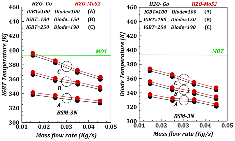
IGBT and Diode temperature changes in BSM-3N geometry.
Mass flow rate strongly reduces temperature, and the use of four blades at the spray outlet causes the fluid to behave more turbulently and produce more vortex currents, which increases the kinetic energy of turbulence (See Figure 8). Increasing the turbulence energy causes the thermal boundary layer to decrease again and the temperature of the devices to be in a limited range, resulting in a further decrease in temperature. Inside electrical modules, due to heat generation, temperature distribution and thermal peak have a significant effect on the efficiency and lifetime of electrical devices. In proportion to the results, in general, with further reduction of the dimensional ratio of the sprays, the thermal distribution is formed at a lower temperature peak. Simultaneous use of nanofluids has satisfactory effects in reducing the temperature, and ultimately creates pleasant thermal effects on the whole module.
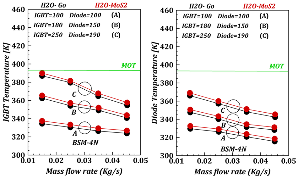
IGBT and Diode temperature changes in BSM-4N geometry.
The aspect ratio of the nozzles has a great effect on the pumping capacity of the fluid. In a deductive diagram between sprays, graphene oxide nanofluid with a volume fraction of 0.01 was performed (See Figure 9). The results show that increasing the nozzles to four outlets leads to an increase in fluid pumping capacity. So that with the increase of mass flow rate up to about 0.05 kg/s, this increase will be much greater. In general, increasing the input current rate increases the pump power, so this increase has the opposite effect on the COP of the system. As the aspect ratio of the sprays decreases, this COP decrease becomes more and more. Although it is not possible to achieve the desired result in this design, but the most ideal COP with a criterion of 20,000 is BSM-4N spray, because it has stronger cooling compared to other spray models and has satisfactory values of COP.

COP changes and Pp in four different geometries.
The use of nanofluids reduces the temperature gradient. The reason for this is that the hydrodynamic effects of the fluid increase with the addition of nanoparticles (See Figure 10). In fact, increasing the conductivity of the fluid increases the cooling power, so with increasing the volume fraction of nanoparticles, the temperature decreases. In fact, the addition of nanoparticles increases the conductivity of the fluid, and this increase in conductivity leads to a wave that also increases the cooling capacity of the base fluid. At the same time, it can be assumed that the presence of nanoparticles themselves causes the behavior of the fluid to change and experience turbulent effects. This, in turn, disturbs the flow, causing the hydrodynamic effects to overwhelm the thermal effects again, resulting in stronger cooling. It can also be found that reducing the temperature difference also reduces exergy.

Temperature changes for different concentrations of H2O-GO.
The use of blades in the nozzles reduces the dimensions of the spray gun. This increases the velocity of the fluid. As the velocity of the fluid increases, the behavior of the fluid layer changes and eventually becomes turbulent (See Figure 11). Increasing the fluid velocity actually increases the hydrodynamic power and makes the fluid have a stronger cooling along the channel. Increasing the hydrodynamic effects weakens the thermal effects and eventually reduces the thermal peak. In fact, as the fluid velocity increases, the friction factor decreases. As turbulent behaviors increase with increasing velocity of the fluid and more vortex currents occur, the effect of drag force also decreases. This is so that the intensity of the fluid ejection increases and the hydrodynamic effects overcome the viscous effects. In fact, it can be seen that throwing the fluid with more intensity causes the behavior of the fluid to be more chaotic along the channel. Therefore, along the duct, the velocity of the fluid that enters from the BSM-4N nozzle is faster than other nozzles.

Velocity changes in different sprays.
Reducing the aspect ratio of the nozzles helps to increase the velocity of the fluid and spray the nanofluids (See Figure 12). By reducing the aspect ratio of the nozzles from 1 to 0.25, the strength of the fluids in cooling increases and they have more power in cooling. With increasing heat flux, we can see that initially the internal temperature is more than 420 K, and at the same time as the ratio of sprays decreases, the maximum temperature decreases. One of the most obvious reasons is that by reducing the aspect ratio of the nozzles, increasing the speed and strength of the jet fluid can provide more efficient cooling. The reason for this effect is related to the increase in turbulence effects. With increasing speed of kinetic energy, we will see an increase in TKE turbulence, so this leads to satisfactory results in terms of cooling. In fact, when the fluid collides with these blades, vortex currents are created and this causes turbulence. In the no-blade model (SSM) spray, the major concentration of turbulence kinetic energy is limited to the spray nozzle rim, which means that turbulence effects do not play a strong role in cooling using this spray. However, the use of blades and increasing the number of openings actually reduces the dimensions of the openings, which makes the turbulent kinetic energy stronger while at the same time a stronger cooling is formed along the channel. In fact, as the spray becomes smaller, the velocity of the fluid is increased and after the fluid collides with the wall of the channel, major vortex currents are created in the same areas. This is satisfactory because, firstly, it enhances the turbulent kinetic energy, secondly, more areas, and of course away from the sprays, are also cooled, so less thermal peak is created in the electrical module.

TKE changes in different sprays.
Conclusion
This paper evaluates the stable 3D simulation of a power module using nozzles for launching cooling nanofluids (H2O-GO and H2O-MoS2). The effects of nanofluid flow velocity, different spray shapes, heat flux, and volume fraction of nanofluid on cooling and hydraulic performance have been investigated. The four types of sprays used include simple spray model (SSM), one- blade spray model (BSM-1N), three-blade spray model (BSM-3N), and four-blade spray model (BSM-4N). This optimization has been done using ANSYS-FLUENT software and with different methods for each part. Due to the current turbulence, the Realizable model is used in the software, and also the QUICK and PRESTO methods 34 will be used to detect the kinetic energy equations in the turbulence and pressure flow, respectively. Results showed that:
With further reduction of the dimensional ratio of the sprays, the thermal distribution is formed at a lower temperature peak.
Increasing the input current rate increases the pump power, so this increase has the opposite effect on the COP of the system.
The use of GO nanoparticle has better heat transfer than MoS2 nanoparticle due to its higher thermal conductivity.
By reducing the aspect ratio of the nozzles from 1 to 0.25, the turbulent kinetic energy in the module areas (IGBT, Diode) increases.
With increasing the volume fraction of GO nanoparticle from 0.01 to 0.05, due to the increase in thermal permeability coefficient, in sensitive areas (IGBT, Diode) the temperature drops further
Finally, with regard to the value of electronic processors, we can prevent the waste of energy consumed and created better heat transfer in the system by optimizing the electronic module, employing a novel micro-sprayer and nanofluid (GO-H2O).
Footnotes
Appendix
Acknowledgements
The authors would like to acknowledge the Department of Mechanical Engineering, Babol Noushirvani University of Technology, Iran.
Handling Editor: Chenhui Liang
Declaration of conflicting interests
The author(s) declared no potential conflicts of interest with respect to the research, authorship, and/or publication of this article.
Funding
The author(s) received no financial support for the research, authorship, and/or publication of this article.
Ethics approval
This article does not contain any studies with human participants or animals performed by any of the authors.