
Abstract
The digital valve distribution axial piston pump is a swashplate rotary piston pump, the force on slippers is different from that of traditional axial piston pump. At the same time, the control strategy of the distribution valve will affect the pressure in the piston cavity, and then affect the oil film lubrication. According to these characteristics, the modeling method of oil film thickness field was proposed, and the force model of slipper pair and the numerical solution model of oil film lubrication of digital valve distribution axial piston pump were further established. The influence of swashplate rotation speed, swashplate inclination angle, and distribution valve control strategy on the characteristics of oil film lubrication were solved. The results show that the established thickness field model of oil film conforms to the stress characteristics of the slipper of the valve distribution pump. Increasing the swashplate rotation speed and the swashplate inclination angle is beneficial to optimize the oil film lubrication performance. The discharge valve should be opened in advance or closed in delay, which is beneficial to prevent eccentric wear and adhesion wear of slippers. The research results can provide theoretical basis for the optimal design of valve distribution axial piston pump.
Introduction
Axial piston pump is widely used in construction machinery, aerospace equipment, construction machinery, and other fields because of its high power density, compact structure, and high precision.1–3 The axial piston pump with port plate is restricted by the limit value [pv] that can be borne by the friction pair at high pressure and large flow rate due to the existence of the friction pair of the closely matched port plate end face, and it is sensitive to medium pollution, which is prone to the phenomena such as eccentric wear and plate burning of the port plate.4–7 Compared with the port plate, in the high-pressure and high-flow conditions, the unstable working medium (strong corrosiveness, poor lubricity, etc.), and the high requirements for sealing performance, the valve distribution piston pump will be more used to achieve high pressure and high efficiency.8–10 The traditional axial piston pump is that the cylinder rotates, and the piston reciprocates under the action of a fixed swashplate to realize the process of oil suction and discharge. The valve distribution axial piston pump is that the swashplate rotates while the cylinder does not move, and the most direct difference for the stress of the slipper pair is that the centrifugal force is eliminated.11,12 How to improve oil film lubrication characteristics of slipper pair of axial piston pump is a difficult point in this field.13–15
In the research field of digital valve distribution piston pump, Huang et al. 16 theoretically analyzed the dynamic performance of the distribution valve of hydraulic piston pump, and studied the distribution characteristics and influencing factors of the pump through simulation. Yan et al. 17 developed a simulation model for a high-speed valve distribution system and studied the high-speed valve’s dynamic flow characteristics. The effects of both the cone and ball valve spool configurations on the flow characteristics of the system were primarily reflected in the spool’s closing stroke. Li et al. 18 studied the flow characteristics of a high-frequency reciprocating pump with a check valve distribution and analyzed the reasons why the output flow of the pump was still bottlenecked despite the fact that the frequency response of the check valve met the system requirements. Qian et al. 19 proposed a new type of double-swash-plate hydraulic axial piston pump with port valves. The effects of distribution valve, working pressure, and speed on flow distribution characteristics were studied. It was concluded that the working principle of the pump was feasible.
In the research field of piston pump slipper pair, Xu et al. 20 established the simulation model of oil film coupling relationship of slipper pair by MATLAB programming, and proposed a new method to study the dynamic characteristics of oil film of slipper pair. Tang et al. 21 in order to improve the lubrication characteristics of the slipper pair of axial piston pump, put forward a formula of thermal balance gap of slipper pair based on the law of energy conservation of control body. Hu et al. 22 conducted theoretical and experimental research on the dynamic pressure bearing law of slipper pair of axial piston pump in steady state, and established the friction dynamics model of slipper pair in steady state. It was concluded that there was always a wedge-shaped convergence gap between slipper and swashplate, which was beneficial to the formation of dynamic pressure oil film of slipper pair, and the tilting azimuth of slipper was basically stable at around 170°. Schenk and Ivantysynova23,24 established the simulation tool CASPAR for calculating the oil film of friction pair of swashplate axial piston pump, carried out fluid solid thermal coupling simulation research on the sliding shoe pair, obtained the distribution of temperature field, pressure field, and thickness field under the time-varying clearance of the slipper pair, and analyzed the non isothermal elastohydrodynamic lubrication of key friction pairs. Bergada et al. 25 proposed a new analytical model based on Reynolds equation, which was used to calculate the leakage and pressure distribution of the slipper pair of axial piston pump considering the influence of no groove. It was found that tangential velocity had influence on groove pressure and slipper leakage.
At present, most of the researches on slipper pair of piston pump are port plate or cylinder rotary piston pump. Based on the existing researches, this paper establishes a coupling solution model of oil film of slipper pair for digital valve distribution axial piston pump. The established model of oil film thickness field of slipper pair can intuitively express the overturning state of slipper, and couple it with oil film pressure field model and kinematics model, use Matlab programming to solve the dynamic characteristics of oil film lubrication. The simulated pressure pulsation of piston cavity of valve distribution piston pump under actual working conditions is used as the program input. On this basis, the distribution of oil film pressure field of slipper pair is analyzed, and the influence of different swashplate rotation speed, different swashplate inclination angle, and the control strategy of the flow distribution valve on oil film lubrication characteristics is studied, and the control strategy of the flow distribution valve is optimized, so as to weaken the overturning degree of slipper pair and optimize the oil film lubrication characteristics.
Oil film lubrication model of slipper pair of digital valve distribution axial piston pump
Structure and kinematics model
As shown in Figure 1, the structural diagram and force analysis of the digital valve distribution axial piston pump show that when the pump works, the swashplate is driven by the transmission shaft to rotate and the cylinder body does not move.

Structure of digital valve distribution axial piston pump and stress analysis of slipper pair.
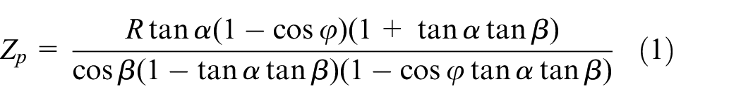
The axial displacement of the piston of the digital valve distribution axial piston pump is as follows:
Axial velocity of piston:

Acceleration:
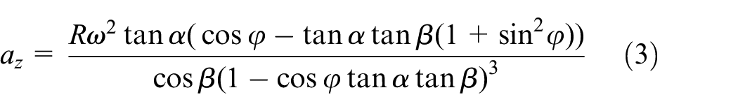
Where Zp is the axial displacement of the piston (m), R is the radius of piston distribution circle (m), ω is the angular velocity of swashplate (rad/s), α is the swashplate inclination angle (rad), ϕ is the swashplate rotation angle (rad), β is the taper angle of piston hole of cylinder body (rad), Vz is the axial velocity of piston (m/s), az is the axial acceleration of piston (m/s2).
If β is 0 and ϕ = 2πnt/30 (n is the swashplate rotation speed, t is the time), the inertia force of piston and slipper can be obtained from formula (3) as follows:

The pre-pressing force of the central spring on the slipper is as follows:

The hydraulic oil pressure in the piston on the slipper is as follows:

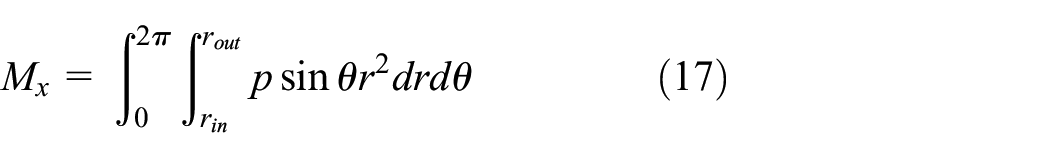
The central chamber pressure of slipper and the oil film pressure field supporting force on the slipper is as follows:

Where ms is the quality of pistons (kg), mp is the quality of slippers (kg), Δx is the compression distance of central spring (m), k is the stiffness of central spring (N/m), px is the number of pistons, d is the diameter of piston (m), p0 is the pressure of piston chamber (Pa), pp is the central chamber pressure of slipper (Pa), p is the pressure at any point of the oil film seal (Pa), rin and rout are the inner and outer radius of the oil film seal (m).
Oil film thickness field model of slipper pair
The swashplate of valve distribution axial piston pump rotates while the cylinder body does not move, so the slipper pair is not affected by centrifugal force, and the friction is the main cause of slipper overturning. It can be predicted that the overturning direction of slipper is mainly determined by the action direction of friction. In view of this feature, in order to intuitively express the overturning phenomenon of the slipper pair, as shown in Figure 2, ignore the rotation of the slipper itself and establish the object coordinate system O-XYZ of the slipper pair, take the oil film bottom surface of the slipper pair as the O-XY plane, take the direction of the connecting line between the swashplate rotation center and the center of the slipper bottom as the Y axis, and the direction perpendicular to the Y axis is the X axis. Due to the symmetrical structure of the slipper, the action direction of the friction force moment is the X axis direction. The overturning angle of the slipper about the X axis is θx, about the Y axis is θy. The thickness of oil film center of slipper pair is hc.

Schematic diagram of oil film thickness field model and pressure field numerical dispersion.
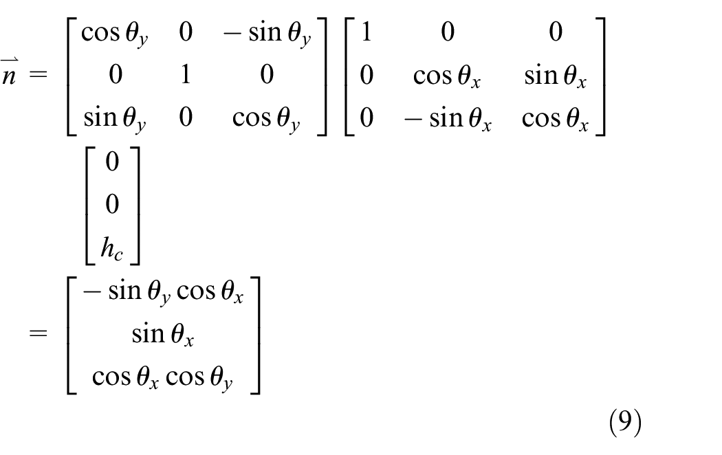
Assuming that the slipper does not overturn at first, the normal vector of the plane where the bottom of the slipper lies is:

The overturning of slipper is decomposed into rotation θx and θy around X axis and Y axis respectively, then the normal vector becomes:
According to formula (9), the equation of the plane where the bottom surface of the slipper lies can be deduced as follows:

Where x, y, and z are the coordinate values of X, Y, and Z axis.
According to formula (10), the z value is the thickness value, so the oil film thickness at any point of the slipper pair in the cylindrical coordinate system can be obtained as follows:

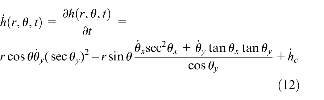
Calculate the partial derivative of equation (11), and the change rate of oil film thickness at any point can be obtained as follows:
Model of oil film pressure field of slipper pair and derivation of torque on slipper
Assuming that the fluid in the oil film is incompressible and laminar, the change of oil film pressure in the thickness direction is ignored. According to the continuity equation and N-S equation, the Reynolds equation of oil film of slipper pair in cylindrical coordinate system can be deduced as follows:

On the basis of the research in Tang et al., 26 the friction torque on the slipper of valve distribution axial piston pump is deduced. As shown in Figure 3, the directions of the X and Y axis are determined by the analysis in 1.2. The swashplate rotates around the swashplate rotation center to form a slipper friction pair with the bottom surface of the slipper, and vs in the figure is the oil velocity.

Schematic diagram of relative movement between slipper and swashplate.
Ignoring the rotation of the slipper itself and combining with the geometric relationship in Figure 3, it can be deduced that the oil velocity of oil film in cylindrical coordinate system is as follows:

Based on the oil film pressure field, the radial and circumferential shear stresses of oil film are as follows:

Where μ is the dynamic viscosity of oil (N s/m2), vsr and vsθ are the radial velocity and circumferential velocity of oil (m/s), lm is the distance between any point on the surface of the slipper and the swashplate rotation center (m), lr is the distance between the center of bottom surface of slipper and the swashplate rotation center (m), γ is the angle between oil velocity and circumferential partial velocity (rad), lc is the distance between the center of bottom surface of the slipper and the center of the ball hinge of the slipper (m), τr and τθ are the radial shear stress and circumferential shear stress of oil film (Pa).
It can be further deduced that the friction torque generated about the Y axis of the coordinate system is as follows:

The oil film pressure torque about the X and Y axis are as follows:

Coupling solution of oil film lubrication model of slipper pair
Numerical solution of model
Considering the pressure loss of hydraulic oil in the piston damping pipe, the central chamber pressure of slipper is as follows:

Where λ is the oil resistance coefficient along the way, ρ is the oil density (kg/m3), l and dl are the length and diameter of piston damping hole (m), Qs is the leakage flow of slipper pair (m3/s).
As shown in Figure 2, the dynamic Reynolds equation is discretized numerically according to the Finite Volume Method, the calculation domain of the oil film sealing belt is divided into uniform pressure regions through meshing, and the pressure of each mesh node is solved iteratively until the pressure field reaches the iterative convergence condition. Under the polar coordinate system, integrate both ends of equation (13) in the same calculation domain, and the pressure of each node can be obtained as follows:

Further, the thickness value of each node can be obtained as follows:

The characteristic parameters of nodes in equation (20) and (21) are as follows:

Where ai,j, hi,j, ri,j, and θi,j are the solution coefficients, thickness values, radius values, and angle values at the corresponding mesh nodes, Δ r and Δ θ are the spacing radius and angle between mesh nodes, nr and nθ are the number of radial nodes and circumferential nodes of mesh.
Setting initial value of thickness field and boundary conditions of iterative solution:


Where pshell is the shell pressure of pump (Pa).
According to the stress characteristics of the slipper pair of valve distribution axial piston pump, the oil film lubrication coupling solution equation of slipper pair is as follows:

In the iterative solution process of oil film pressure field, firstly, take the dynamic pressure of piston cavity as the program input, with the calculation step of 1.0 × 10⁻⁶ s, solve Reynolds equation by Finite Volume Method, and solve the pressure field iteratively until the pressure field reaches the convergence condition, at which time there is only one unknown quantity (change rate of thickness field) in equation (24). Then, Newton iteration method is used to solve the equation (24), and finite element summation is used in the double integral part to improve the calculation efficiency, and the second cycle is carried out until the convergence condition is reached. Finally, the oil film thickness field is solved by the obtained change rate of the thickness field, and the next cycle is carried out until the end of the solution process. The numerical calculation flow is shown in Figure 4, in which AMESim dynamic simulation of piston cavity pressure of digital pump is introduced in 2.2.

Numerical solution flow of lubricating oil film of slipper pair.
Actual working condition simulation of digital valve distribution axial piston pump
In order to obtain the dynamic pressure of the piston cavity of the digital valve distribution pump and take it as the dynamic input of the Matlab program of the coupling solution model of lubricating oil film, the actual working condition of the digital valve distribution pump is simulated.
Dynamic modeling of distribution valve
At present, the valve distribution piston pump mostly adopts check valve or high-speed on-off valve or both. In order to make up for the lag effect of check valve and the limitation of check valve response time on speed, and combined with the development trend of valve distribution piston pump, the discharge valve adopts high-speed on-off valve and the suction valve adopts spherical check valve. 27 Under the action of electromagnetic force, the valve port of the discharge valve opens and closes quickly. When the piston is in the discharge stroke, the valve port opens quickly. When the piston is in the suction stroke, the valve port closes quickly. Under the action of its own spring and hydraulic pressure, the suction valve closes in the piston discharge stroke and opens in the piston suction stroke. Both discharge valve and suction valve adopt spherical spool, and its dimensional parameters are shown in Figure 5.
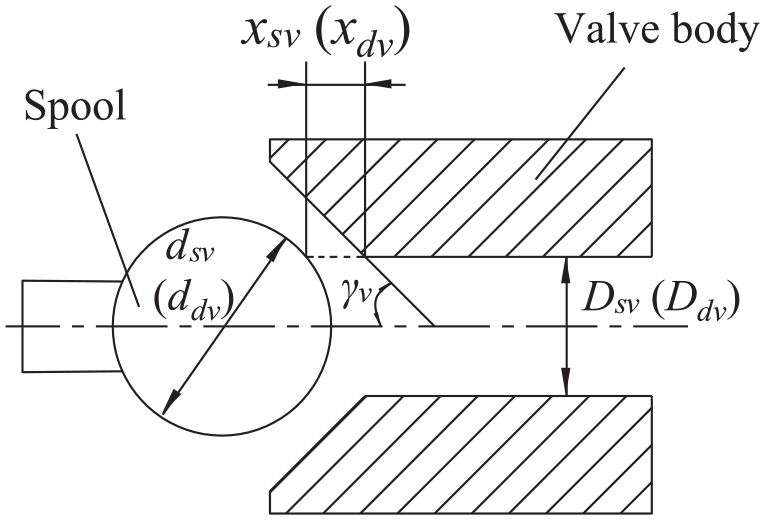
Schematic diagram of distribution valve size parameters.
The overflow area of valve port is as follows:

The flow through the valve port is as follows:
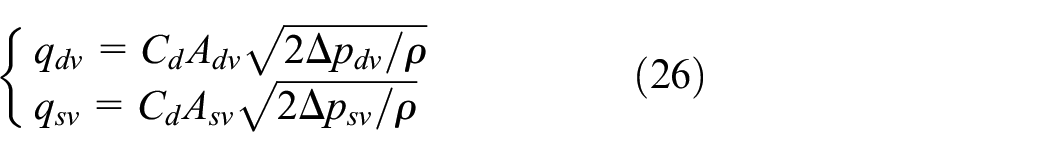
By substituting equation (25) into equation (26):

Where Adv and Asv are the overflow area of discharge valve and suction valve respectively (m2), xdv and xsv are the displacement of discharge valve spool and suction valve spool respectively (m), ddv and dsv are the diameter of discharge valve spool and suction valve spool respectively (m), γv is the half angle of discharge valve and suction valve seat (°), qdv and qsv are the discharge valve flow and suction valve flow respectively (m3/s), Δpdv and Δpsv are the differential pressure at the discharge valve port and the differential pressure at the suction valve port (Pa), Cd is the valve port flow coefficient.
The motion equation of discharge valve is as follows:

The motion equation of the suction valve is as follows:

Where mdv and msv are the spool quality of discharge valve and suction valve respectively (kg), Fdv and Fsv are the resultant forces of steady and transient hydrodynamic forces of discharge valve and suction valve respectively (N), Fe is electromagnetic force (N), kv is the friction coefficient (N/m), pdv and psv are the port pressure of discharge valve and suction valve respectively (Pa), Sdv and Ssv are the action area of hydraulic oil at the valve port of discharge valve and suction valve respectively (m2), ksv is the spring stiffness of suction valve (N/m), Fre is the preload of the suction valve spring (N).
Simulation and analysis of dynamic pressure characteristics of piston cavity
As shown in Figure 6, AMESim simulation model of swashplate rotary axial piston pump (valve distribution axial piston pump) is established. PISTON-1–PISTON-9 are AMESim super components of piston and corresponding distribution valve module. The specific model is shown in Figure 7. The sampling frequency of data is 1.0 × 10⁶ Hz, which is consistent with the calculation step of numerical solution. The simulation parameter settings of distribution valve are shown in Table 1, and other simulation and calculation parameter settings are shown in Table 2.

Model of digital valve distribution piston pump.

PISTON-1 model.
Simulation parameters of distribution valve.

Simulation and calculation parameters.

Figure 8 is the dynamic characteristic curve of piston cavity pressure under different working conditions, with 0°–180° as piston discharge stroke and 180°–360° as piston suction stroke.
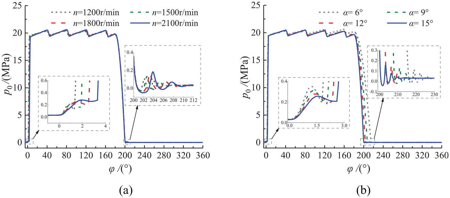
Piston cavity pressure under different swashplate parameters: (a) swashplate rotation speed and (b) swashplate inclination angle.
The swashplate rotation speed and swashplate inclination angle will not only directly affect the acceleration of the reciprocating motion of the piston, resulting in the change of the inertia force of the slipper, but also affect the dynamic characteristics of the piston cavity pressure. Through simulation, the dynamic characteristic curves of piston cavity pressure at different swashplate rotation speed when the swashplate inclination angle is 15° and the dynamic characteristic curves at different swashplate inclination angle when the swashplate rotation speed is 1500 r/min are obtained, as shown in Figure 8(a) and (b), respectively. From the graph analysis, it can be seen that the smaller swashplate rotation speed and swashplate inclination angle, the shorter the time for establishing pressure at the initial time of oil discharge, which is due to the shorter transition time between piston discharge stroke and piston suction stroke. The larger the swashplate rotation speed and swashplate inclination angle, the more intense the pressure oscillation in the piston cavity at the initial time of oil suction, and this local oscillation is mainly caused by the spring stiffness of the suction valve. The larger the swashplate rotation speed, the larger the pressure pulsation of the piston of the valve distribution piston pump during the transition from the discharge stroke to the suction stroke. The larger the swashplate inclination angle, the shorter the pressure relief time of the piston during the transition from the discharge stroke to the suction stroke, and causing a sudden change in pressure, which is not conducive to the stability of the oil film of the slipper.
To make the performance of a high-speed on-off valve fit actual working conditions as closely as possible, and because of the high pressure and large flow in the plunger pump, the opening and closing times should not be too small. According to the dynamic model of discharge valve and the literature,28–30 the discharge valve had a ball valve structure, and a one-dimensional table interpolation method is used to control the opening and closing of the high-speed on-off valve. The opening and closing times are set to 2 ms. The control strategy of the discharge valve is discussed in 10 modes. As shown in Table 3, opening and closing are based on the starting time and ending time of the piston discharge stroke (0 ms) respectively. Set the swashplate inclination angle to 15° and the swashplate rotation speed to 1500 r/min, and get the dynamic characteristics of the pressure in the piston cavity in each mode through simulation, as shown in Figure 9.
Control strategy of discharge valve.


Piston cavity pressure under different control strategies of discharge valve: (a) Early/On time response, (b) Late/On time response, and (c) Late/Early response.
It can be seen from Figure 9(a) that when the discharge valve is opened early, the suction valve is not closed at the moment when the discharge valve is opened, and the piston suction stroke is not finished yet, so the high-pressure liquid enters the piston cavity, so the pressure in the piston cavity will increase in advance when the suction stroke is not finished, and at the same time, the high-pressure state time of the piston cavity will be prolonged, and the pressure pulsation will be obviously weakened. Closing the discharge valve early is beneficial to the timely opening of the suction valve to prevent the piston from sucking oil back from the system. However, if the discharge valve is closed before the end of the piston discharge stroke, the pressure in the piston cavity will rise sharply and increase the pressure pulsation.
It can be seen from Figure 9(b) that opening the discharge valve late can make up for the lagging response of the suction valve, so that the pressure pulsation is reduced. Closing the discharge valve late will hinder the opening of the suction valve and increase the pressure pulsation.
It can be seen from Figure 9(c) that opening early and closing late the discharge valve can prolong the high pressure state time of the piston cavity to the greatest extent. Opening late and closing early the discharge valve can obviously reduce the pressure pulsation, but the delay and advance time can’t exceed the lag effect range of the check valve, so as to prevent the discharge from being blocked. For example, there are pressure spikes at the left and right ends of Mode X, and the pressure peak at the right end is more obvious because it takes time for the discharge valve to close itself. In the above analysis, Mode I–IX have different effects on the pressure characteristics of the piston cavity. Since mode X does not conform to the pressure characteristics under the actual working state, it will not be discussed in the subsequent analysis.
Dynamic characteristics analysis of oil film lubrication of slipper pair
Swashplate is the key component of power transmission of digital valve distribution axial piston pump, and swashplate rotation speed and swashplate inclination angle are two important parameters. In addition, high-speed on-off valve (discharge valve) and check valve are used to replace the traditional port plate, so the on-off characteristics of the high-speed on-off valve directly affect the dynamic response of piston cavity pressure, thus affecting the oil film lubrication performance. Input the dynamic pressure of piston cavity into the model solving program, and carry out numerical calculation.
Pressure field distribution of oil film
When the swashplate speed is 1500 r/min, the swashplate inclination angle is 15°, and the discharge valve control strategy is mode V(0 ms, +2 ms), the thickness field and the change rate of the thickness field under different Swashplate rotation angle are substituted into the Reynolds equation of oil film lubrication, and the pressure field distribution of oil film of the slipper pair is solved and obtained, as shown in Figure 10.
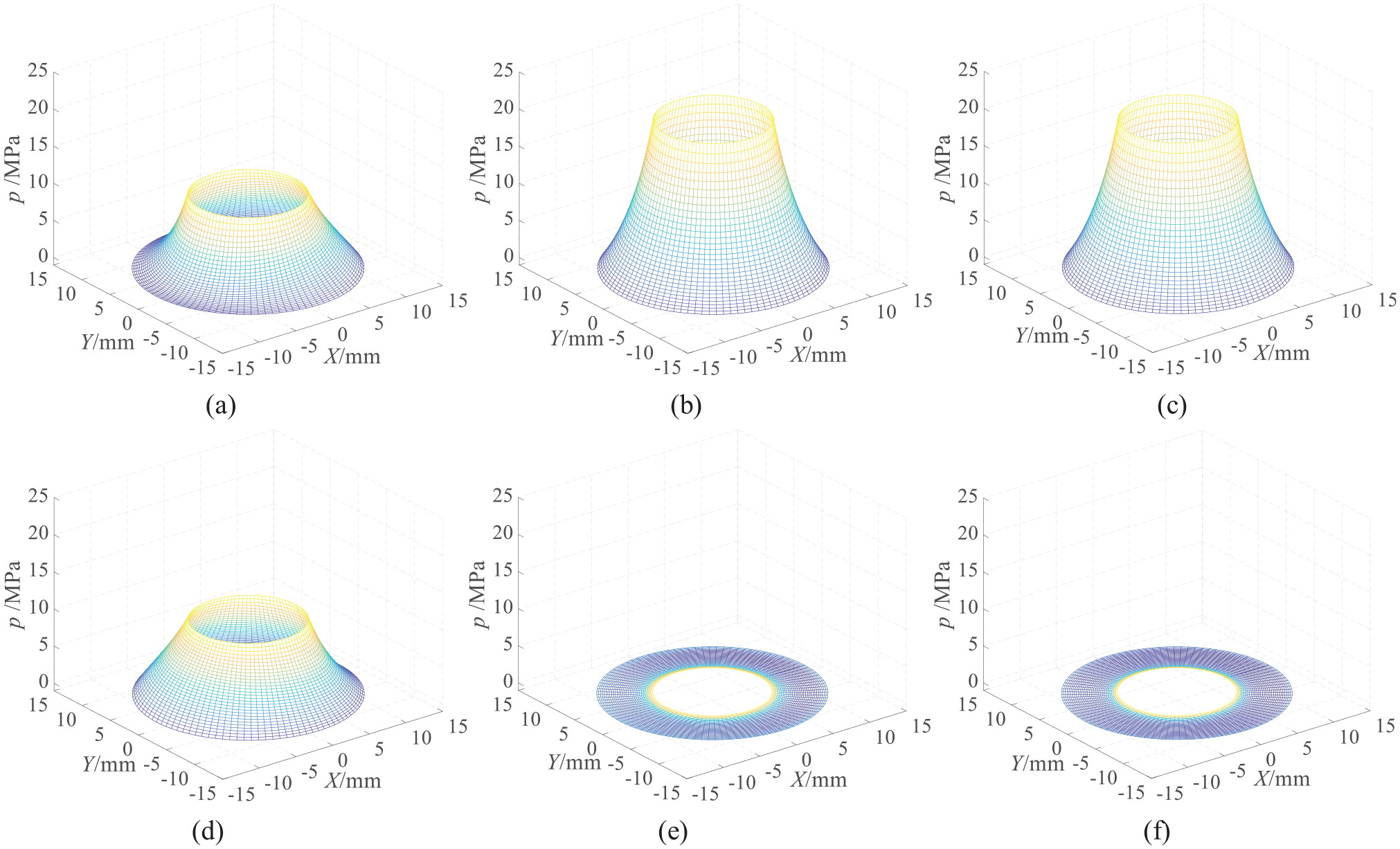
Distribution of oil film pressure field under different swashplate rotation angle: (a) 4.5°, (b) 90°, (c) 180°, (d) 184.5°, (e) 270°, and (f) 360°.
In Figure 10, Figure (b) and (c) show the oil film pressure distribution in the piston discharge stroke. The piston cavity pressure basically reaches the maximum value, the pressure field is evenly distributed. Figure (e) and (f) show the oil film pressure distribution in the piston suction stroke. The pressure value is the lowest, and the uneven pressure field distribution easily leads to the slipper overturning. Figure (a) and (d) respectively show the oil film pressure distribution during the transition period from piston oil suction to oil discharge and the transition period from oil discharge to oil suction. It can be seen that the uneven distribution of the pressure field. The influence of the friction torque cause the pressure distribution in Figure (d) to drop rapidly along the positive direction of the X axis and slowly along the negative direction of the X axis. The opposite is true in Figure (a). The pressure distribution in the single direction of the X axis is uneven, which is very easy to cause the overturning of the slipper about the Y axis.
Influence of swashplate rotation speed and swashplate inclination angle on oil film lubrication performance
The calculation results obtained by changing the swashplate rotation speed and the swashplate inclination angle are shown in Figures 11 and 12, with 0°–180° as the piston discharge stroke and 180°–360° as the piston suction stroke.

Thickness field under different swashplate rotation speed: (a) thickness of oil film center, (b) overturning angle θx, and (c) overturning angle θy.
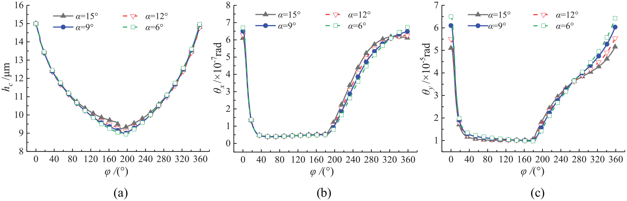
Thickness field under different swashplate inclination angle: (a) thickness of oil film center, (b) overturning angle θx, and (c) overturning angle θy.
Based on the analysis of Figures 11 and 12, it can be seen that during the piston discharge stroke, the thickness of oil film center decreases continuously, and the overturning angle of the slipper θx and θy basically stabilize at the minimum value after the sharp decline in the transition period from the piston suction stroke to the discharge stroke. According to the analysis of 3.1, it can be seen that the oil film pressure field is evenly distributed at this time, the pressure value is large, and the oil film is weakly affected by the dynamic pressure effect, which mainly causes a certain overturning around the Y axis under the influence of the friction torque, and a small overturning angle around the X axis, which is mainly affected by the dynamic pressure effect and the pressure field distribution difference caused by the friction torque. During the piston suction stroke, the thickness of oil film center keeps increasing, which is caused by the pressure relief of the piston cavity during the suction stroke and the axial stress change of the slipper. The overturning angle θx and θy keep increasing, reaching the maximum during the transition period of the piston from the suction stroke to the discharge stroke. At this time, the pressure of the piston cavity changes sharply, which is also the dangerous period of eccentric wear of the slipper. Overturning angle θx continuously and uniformly increases in the suction stroke, and gradually stabilizes or decreases at the end of the stroke, because at this time, the dynamic pressure effect plays a role to restore the oil film to a certain bearing capacity, while overturning angle θy gradually increases slowly in the first half of the suction stroke, and gradually accelerates in the second half of the suction stroke, which is related to the change of acceleration of the piston in the suction motion, which causes the inertia force on the slipper to continuously decrease to zero at first and then increase reversely. On the whole, because the slipper is not affected by centrifugal force, the overturning angle θx is mainly affected by dynamic pressure effect, but little by swashplate rotation speed and swashplate inclination angle, and its value can be neglected relative to the overturning angle θy, but the overturning angle θx just reflects the influence law of dynamic pressure effect on oil film lubrication performance in the discharge stroke and the suction stroke to a certain extent.
From Figures 11 and 12, it can be seen that the larger the swashplate rotation speed, the smaller the overturning angles θx and θy, and the milder the change, so that the slipper is not prone to eccentric wear. At the same time, the thickness of oil film center increases, which reduces the risk of adhesion and wear of slipper. The larger the swashplate inclination angle, the smaller the overturning angles θx and θy, and the larger the thickness of oil film center. This is because when the swashplate inclination angle increases, the axial impact force on the oil film of the slipper pair decreases. This shows that under the condition that other parameters of piston pump are constant, the larger the swashplate rotation speed and swashplate inclination angle, the more uniform the distribution of oil film pressure field, which is beneficial to the formation of pressure lubricating oil film of slipper pair, which is just contrary to the analysis in 2.2. However, due to the influence of the structure of the digital valve distribution axial piston pump and the performance of the distribution valve, the swashplate inclination angle and the swashplate rotation speed should not be too large.
Influence of control strategy of discharge valve on oil film lubrication performance
Figures 13 and 14 show the calculation results of thickness field under different control strategies of discharge valves. When the pressure pulsation characteristics of the piston cavity are input into the program, a complete cycle of high pressure and low pressure of the piston cavity is taken in each mode. The overall change trend of the thickness field is similar to the analysis in 3.2.

Thickness field under Early/On time response: (a) thickness of oil film center, (b) overturning angle θx, and(c) overturning angle θy.

Thickness field under Late/On time and Late/Early response: (a) thickness of oil film center, (b) overturning angle θx, and (c) overturning angle θy.
In the transition period from the discharge stroke to the suction stroke of the piston, the oil film pressure changes sharply at this time, and the slipper pair is in an unstable period. At this time, it can be seen from Figures 12(a) and 14(a), the modes I(0 ms, −2 ms), III(0 ms, 0 ms), VI(+2 ms, 0 ms), VII(+2 ms, +2 ms), and IX(+2 ms, −2 ms) will make the thickness of oil film center suddenly change downward, while II(−2 ms, 0 ms), IV(−2 ms, −2 ms), V(0 ms, +2 ms), and VIII(−2 ms, +2 ms) will make the thickness of oil film center suddenly change upward,which is beneficial to prevent the adhesion and wear of slipper. It can be seen from Figure 13(b) and (c) that under the Early/On time response of the discharge valve, the overturning angle θy of mode I(0 ms, −2 ms) is the largest, and the overturning angle θx is obviously the largest in the whole suction stroke, and the dynamic pressure effect is the most obvious, followed by mode III, and modes II and IV are very close. As can be seen from Figure 14(b) and (c), under the Late/On time and Late/Early response of the discharge valve, the overturning angle θy of mode IX is the largest, and the overturning angle θx of the whole suction stroke is the largest at the same time, followed by modes IX, VI, VII, V, and VIII in turn.
The change trend of overturning angle θx and θy under different control strategies of discharge valve is consistent. Analyze the change of the maximum value of main overturning angle θy under different control strategies. As shown in Figure 15, it can be seen from the figure that although the late opening or early closing of discharge valve can reduce the pressure pulsation of piston cavity, the maximum value of overturning angle θy is larger. Early opening or late closing of discharge valve will reduce the overturning angle θy, make the oil film pressure distribution more uniform, which is beneficial to the stability of the slipper pair. This is because early opening or late closing of discharge valve makes the pressure in the piston cavity change more gently during the transition period of the suction and discharge stroke, and keeps the pressure in a high pressure state during the lag period of the check valve opening or closing to prevent sudden pressure change. Combined with the thickness of oil film center during the transition period from discharge stroke to suction stroke and the pressure pulsation shows that the discharge valves adopt the modes II(−2 ms, 0 ms), IV(−2 ms, −2 ms), V(0 ms, +2 ms), and VIII(−2 ms, +2 ms) better.

Overturning angle (θy)max under different control strategies of discharge valve.
Conclusion
In this paper, a coupled solution model of dynamic characteristics of lubricating oil film is established for the slipper pair of the digital valve distribution axial piston pump, and the lubricating characteristics of oil film of slipper pair are analyzed, and the following conclusions are obtained:
The slipper pair of digital valve distribution axial piston pump is not affected by centrifugal force, and shows that the slipper overturns and uneven oil film pressure distribution in a single direction under the influence of friction torque. The value of overturning angle θx is negligible relative to overturning angle θy, but the overturning angle θx is mainly influenced by a single factor of dynamic pressure effect, and its dynamic characteristics can reflect the dynamic pressure effect of oil film. The established thickness field model can well express the characteristics of slipper pair of valve distribution axial piston pump.
The oil film pressure of the slipper pair in the piston discharge stroke of the valve distribution pump is evenly distributed, the overturning angles θx and θy are stable at the minimum, the thickness of oil film center is continuously reduced, and the overturning degree of the slipper is small. The pressure value decreases to the lowest in the suction stroke, the overturning angles θx and θy rise sharply, and the thickness of oil film center increases continuously, and reaching the maximum at the end of the suction stroke. During the transition period between the discharge stroke and the suction stroke, the pressure value changes sharply. Influenced by the friction torque, the pressure distribution in the X-axis direction is obviously uneven, which is easy to cause the slipper to overturn.
The larger the swashplate rotation speed and swashplate inclination angle, the larger the thickness of oil film center and the smaller the overturning angle of the slipper, which is beneficial to the formation of the pressure lubricating oil film of the slipper pair. The swashplate inclination angle has a relatively weak influence on this law.
It is better to adopt control strategies II(−2 ms, 0 ms), IV(−2 ms, −2 ms), V(0 ms, +2 ms), and VIII(−2 ms, +2 ms) for the discharge valve, which is beneficial to prevent the eccentric wear and adhesive wear of the slipper, that is, the discharge valve should be opened in advance or closed in delay (2 ms), and the advance or delay time shall not be too long, otherwise the piston discharge will be blocked and the pressure will rise sharply.
The conclusions are helpful to the optimal design of the digital valve distribution axial piston pump, prevent the eccentric wear and adhesive wear of the slipper pair, and improve the stability and service life of the digital valve distribution axial piston pump.
Footnotes
Handling Editor: Chenhui Liang
Author contribution
Conceptualization, KP.Z. and T.H.; data curation, KP.Z.; formal analysis, KP.Z. and T.H.; funding acquisition, CL.W. and T.H.; investigation, KP.Z. and ZP.L.; methodology, KP.Z.; project administration, CL.W.; resources, ZP.L. and QM.C; software, KP.Z.; supervision, T.H. and QM.C; validation, KP.Z. and T.H.; writing -original draft preparation, KP.Z.; writing review and editing, KP.Z., T.H., and CL.W.
Declaration of conflicting interests
The author(s) declared no potential conflicts of interest with respect to the research, authorship, and/or publication of this article.
Funding
The author(s) disclosed receipt of the following financial support for the research, authorship, and/or publication of this article: This study was financially supported by the National Natural Science Foundation of China (Grant No. 51675003), the Open Foundation of the Anhui Key Laboratory of Mine Intelligent Equipment and Technology (Grant No. ZKSYS202101), the Natural Science Foundation of Anhui Province (Grant No. 2008085QE216), the Open Foundation of the State Key Laboratory of Fluid Power and Mechatronic Systems of China (Grant No. GZKF-201715).