
Abstract
This paper proposes a novel capsule robot (CR) with spring-connected legs for potential usage in the gastrointestinal (GI) tract. The proposed CR has a set of six legs and is actuated by a micromotor through internal mechanisms. Every two adjacent legs are connected by a spring. The leg opening-folding movement, together with the spring stretching-contraction motion, may be employed to distend the GI tract, carry out drug delivery or perform biopsy. The relationship between the driving force required by the spring set and the spring length was carefully calculated and simulated. This relationship was also measured by an NI data acquisition system. The calculated and measured data showed good accordance with each other. In addition, the driving force from the micromotor was calculated. Both the calculations and the CR experiments demonstrated that the internal motor could provide sufficient force on the springs.
Introduction
Capsule endoscope (CE) was first introduced into clinical practice in 2001 and, within just a few years, became the reference standard device for the diagnosis of small bowel diseases beyond gastrointestinal (GI) bleeding. 1
In the past two decades, impressive technological advances have occurred in CE systems to make them much more powerful devices with several additional functionalities, such as active locomotion,2–6 drug delivery,7–11 and biopsy.12–19 Legged capsule robots (CRs), as one of these technologies, have been of interest to many researchers because of their ability to reliably dilate the intestine and stably anchor at a specific site. Expanding the intestinal tract can help reach the folds of the intestine to decrease leak detection, while anchoring can help the capsule not pass too quickly through a suspected area and thus improve the diagnostic accuracy. By the same logic, the use of a legged mechanism can also help improve the accuracy of drug release or biopsy.
Regarding anchoring, the structures of both the end contact parts and the actuation mechanisms have been studied. Bioadhesives20,21 have been employed to establish contact with the GI tract. However, the actuation mechanisms of these bioadhesives both are complex and cannot help the adhesives maintain a particular shape to adapt to intestines of different sizes. The legs of the legged anchoring capsules in Zhou et al., 22 Wang et al. 23 are able to maintain any opening angle to comply with the intestine size because of the employment of a screw mechanism as the intermediary mechanism. However, the legs of these capsules have a small contact area with the intestine. In contrast, although the holding mechanism employed in Woods and Constandinou 24 has a relatively large contact area with the intestine, it can only partially expand the GI tract and lacks a self-locking shape functionality because of its employment of a gear-based intermediary mechanism. Legged walking capsules2–6 always have the ability to anchor. The self-locking shapes of some CRs2–4 are achieved with the help of a screw mechanism, and some other CRs5,6 rely on a worm drive mechanism. However, most of these legged walking CRs still have small contact areas with the intestine, although some have many more legs. A balloon-assisted legged CR 5 may be an exception in that it can provide a large contact area, but its balloon size is not adjustable, and it is probably appropriate for use in the colon only, as it would be detained in the small bowel.
CE systems with drug release functions have been thoroughly investigated by many researchers. Related works have recently been summarized by Alici, 7 Liu et al., 8 and Ivan. 9 However, most of those solutions have nothing to do with stretching legs and thus cannot expand the GI tract and may not be capable of site-specific drug release. The soft CR proposed by Yim and Sitti 10 and the microrobot proposed by Woods and Constandinou 11 may be exceptions. Unfortunately, the former shrinks its size while performing drug delivery, and the latter only partially expands the intestine on one side. Sometimes, multiple drugs are required to be delivered at the same time for combination therapy. 25 However, none of the existing solutions allows for the release of different drugs in multiple drug compartments while expanding the GI tract.
Many biopsy CE systems have also been proposed. The biopsy capsules proposed by Hoang et al., 12 Simi et al., 13 Le et al., 14 and Kong et al. 15 perform sampling by means of a pair of opening-closing hatches. However, the biopsy capsules proposed by Hoang et al., 12 Simi et al., 13 and Le et al. 14 do not have the ability to expand the GI tract. Although the robotic biopsy device proposed by Kong et al. 15 includes a mechanism driven by shape memory alloy (SMA) springs to expand the GI tract, the expansion mechanism is separate from the tissue sampling mechanism, which may weaken the success rate of biopsy. Rehan et al. 16 employed an SMA-spring-actuated rotatable scratcher to sample mucosal tissue. However, that device also does not have the ability to expand the GI tract. Unlike the aforementioned capsules for performing biopsy in the radial direction, Hoang et al. 17 and Son et al. 18 employed an axial retractable needle to harvest biopsy tissue, and Chen et al. 19 designed an axially extendable biopsy jaw for a biopsy capsule. Generally, biopsy CRs are seldom used for biopsy after the intestine has been expanded in advance.
The present study proposes a novel spring-connected leg mechanism for CRs that has the potential to improve anchoring and enable drug release or biopsy. The potential advantages of the device are as follows: first, the ability to expand the GI tract to a certain size while maintaining a relatively large contact area with the intestine; second, the ability to load different drugs in separate drug compartments for multidrug release; and third, the ability to scrape intestinal tissue anywhere on the circumference of a certain circle. Part 2 presents schematics of the CR mechanisms. The structural design and fabrication of the CR are presented in Part 3. Part 4 analyzes the driving force on the nut in the CR from the perspectives of both the spring and the internal micromotor. Experiments investigating the relationship between the nut driving force and the spring length, together with experiments on the entire CR prototype, are described in Part 5. Part 6 discusses the experimental data and the influence of the spring characteristic parameters on the nut driving force. Part 7 presents our conclusions.
Schematics of the capsule robot mechanisms
An actuation schematic of the CR internal mechanisms is depicted in Figure 1. It is mainly composed of a DC motor, a pair of engaged spur gears, a screw pair, a set of brace bars, and a group of legs. The output of the motor is transmitted to the screw pair by the engaged spur gears. The axis of the screw is located on the main axis of the CR. In turn, the lead screw drives its nut. Each brace bar is connected to the nut on one end, and on the other end, it is connected to the middle of a corresponding leg, one of whose ends is mounted on the capsule shell. Thus, when the brace bars move under the pushing of the nut, the legs are driven to rotate and stretch out.

Schematic of the CR internal mechanisms.
The group of legs consists of six legs in total. Every two adjacent legs are connected by a spring. Therefore, it is not easy for the legs to stretch out because of the spring force. Initially, the group of springs forms the shape of a circle due to the adjacent cylindrical surface of the CR shell (Figure 2(a)). After the legs are stretched out, the layout of the springs is similar to a hexagon (Figure 2(b)).

Spring layout of the CR: (a) initial spring layout and (b) stretching-out spring layout.
When the legs are being stretched out, two corresponding effects will occur. On the one hand, the adjacent intestinal lumen will probably be distended, thereby facilitating highly accurate diagnosis. On the other hand, the springs will increase in length. During their deformation from a short length to a longer length, the springs can be employed for drug delivery if the drug is stored inside the springs in advance. Similarly, when the springs reduce in length from their stretched state, they may be able to store some intestinal tissue if the tissue is suitably scraped down from the GI tract beforehand. In the following text, this paper focuses on the mechanism of the spring-connected legs.
Design and fabrication of the capsule
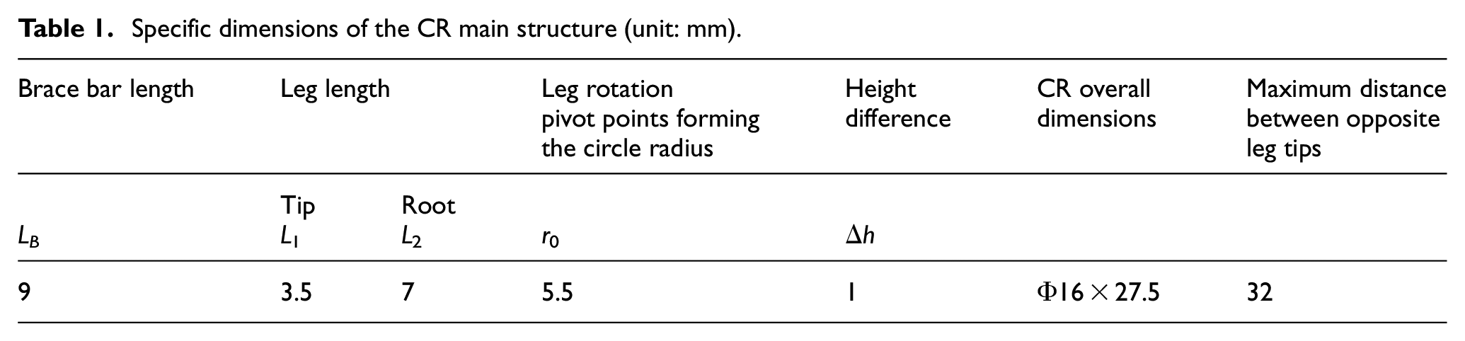
The critical dimensions of the CR internal structure, for example, the brace bars and legs, are labeled in Figure 1, and their specific values are shown in Table 1. A three-dimensional (3D) structure diagram of the CR is depicted in Figure 3. The entire CR prototype has a diameter of approximately 16 mm and a length of approximately 27.5 mm, and the maximum distance of two opposite stretching-out leg tips are approximately 32 mm.
Specific dimensions of the CR main structure (unit: mm).

3D structure diagram of the CR (without the set of springs connecting the legs).
The CR shell and the legs are made of resin material and were fabricated by a 3D laser printer. The use of resin-printed parts significantly reduces the CR weight while maintaining sufficient strength. The use of 3D printed legs also helps reduce the fabrication cost because of their variable cross section. Other parts were fabricated by machining because of the need for assembly precision or the lack of availability of 3D printing services for parts with smaller characteristic sizes. During assembly, the connections between parts were established with carbon rods or steel wire, and appropriate dispensing of glue onto the joints helped ensure reliability. The entire CR prototype is mainly composed of 25 parts in 11 categories (not including the carbon rods or steel wire). Figure 4(a) shows the main parts of the CR, and Figure 4(b) shows the assembled prototype of the CR.
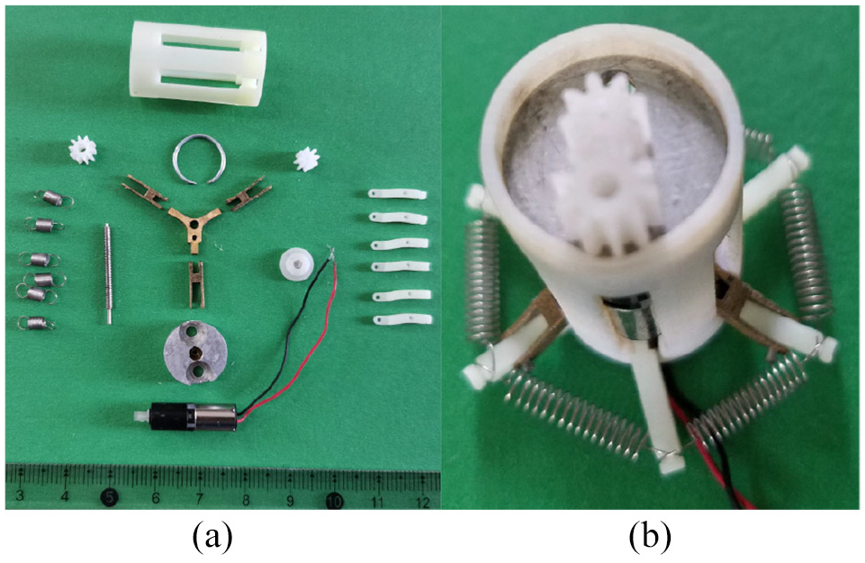
Main parts and the assembled CR prototype: (a) main parts and (b) assembled CR.
Force analysis
Driving force on the nut required for the stretching of the springs
The driving force on the nut that is required to stretch the spring group is critical to the operation of the CR and is analyzed here.
The circle formed by the six rotation pivot points between the nut and the six brace bars has the same radius r0 as the circle formed by the six rotation pivot points between the six legs and the CR shell. There is a slight height difference Δh between the two ends of the legs to avoid a dead point state in the initial position of the legs. However, to simplify the computation, this height difference Δh is ignored. Because of the omission of Δh, the actual opening angle α′ of the legs and the actual opening angle θ′ of the rods (Figure 1) are regarded as the nominal angles α and θ, respectively. The length of the leg tip, the leg root, and the total leg are expressed as L1, L2, L1 + L2, respectively; and the brace bar length is denoted by LB (Figure 5).
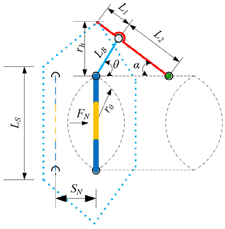
Structural dimensional relationships within the CR.
The movement distance SN of the nut can be calculated as

Through triangulation, the radial extension height rh of the leg tip can be calculated as

When the springs are not in contact with the capsule shell, the spring length LS is actually the sum of the leg-tip radial extension height rh and the radius r0 of the circle formed by the leg rotation pivot points, that is,

The spring force FS can be calculated as

where kS is the spring stiffness and LS0 is the original spring length.
According to the virtual work principle, when the driving force FN on the nut moves a virtual distance of δ(SN), the leg tip generates a corresponding virtual distance of δ(rh) in the radial direction, and the spring length undergoes a virtual increment δ(LS). Ignoring the interaction between the capsule and the outside world, we have

where n is the number of the springs, n = 6.
The relationship between the two rotation angles α and θ can be expressed as

Then, the relationship between the two virtual rotation angles δα and δθ can be expressed as

Finally, the driving force FN can be calculated as
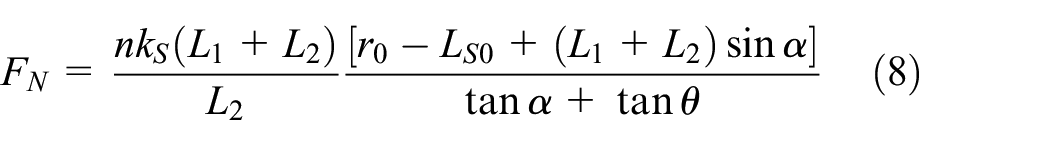
When the sum of the original lengths of the six springs is exactly equal to the circumference of the capsule shell, LS0 is approximately 8.38 mm. By substituting the specific parameter values into (8), the relationship between the driving force FN and the leg opening angle α can be plotted as shown in Figure 6.

Calculated relationships between the driving force FN and the leg opening angle α for different spring stiffnesses ks. Note that an original spring length of LS0 = 8.38 mm is used for all curves.
Driving force from the internal motor
The internal DC motor has an outer diameter of approximately 6 mm, a total length of approximately 20.15 mm and an output torque of approximately 2.55 mN m (TM = 2.55 mN m). The motor output torque is transmitted to the internal screw through a spur gear pair.
Thus, the relationship between the motor output torque TM and the torque TS exerted on the screw can be expressed by the following equation:

where iG is the transmission ratio of the spur gear pair, ηG is the transmission efficiency of the spur gear pair, and ηB is the transmission efficiency of the pair of bearings supporting the screw, which is always in the range of 0.97–0.99.
The axial thrust exerted on the nut by the screw can be expressed as

where DT is the nominal diameter of the screw thread; γT is the lead angle of the screw thread,
Main parameters of the intermediate transmission mechanism.

By substituting the specific parameter values into the above equation, the axial thrust exerted on the nut by the screw is calculated to be approximately 10.44 N, which is a much larger value than the peak thrust required by the springs.
Experiment
Driving force on the nut required for the stretching of the springs
The experimental setup and the data acquisition program panel are shown in Figure 7. In this experiment, the motor and transmission mechanism were not used. Every leg was pushed to rotate by the internal nut via the corresponding brace bar. The nut inside the CR was directly driven by one end of an external rod, with an external screw pushing on the other end of this rod. The external nut mated to the external screw, together with the CR shell, was mounted on the experimental bench. The rod was actually composed of two sections, with a force sensor (Futek LSB205-FSH04101) installed between them. Thus, when the external screw started to work, the driving force on the internal nut was detected by the force sensor.

Experimental apparatus.
The force sensor, together with its amplifier, had a measurement range of 8.9 N and a measurement accuracy of 0.1%. The sensor data were received and processed by an NI data acquisition system, which was mainly composed of an NI PXI-compatible chassis (NI PXIe-1084), an NI PXI-compatible system controller (NI PXIe 8840), a data acquisition card (NI PXIe 6366), and LabVIEW 2019.
The movement distance of the nut was measured with a Vernier caliper and transformed into the corresponding leg angle α. In this experiment, a set of springs with a stiffness of approximately 0.06 N/mm (kS = 0.06 N/mm) and an original length of approximately 7 mm (LS0 = 7 mm) was employed. The measured data are shown in Figure 8. Considering that the possible error between the calculated and measured values caused by the height difference Δh during the initial extension of the legs and the spring length should be greater than the original spring length, both the calculated and measured curves start at an angle of 20°.
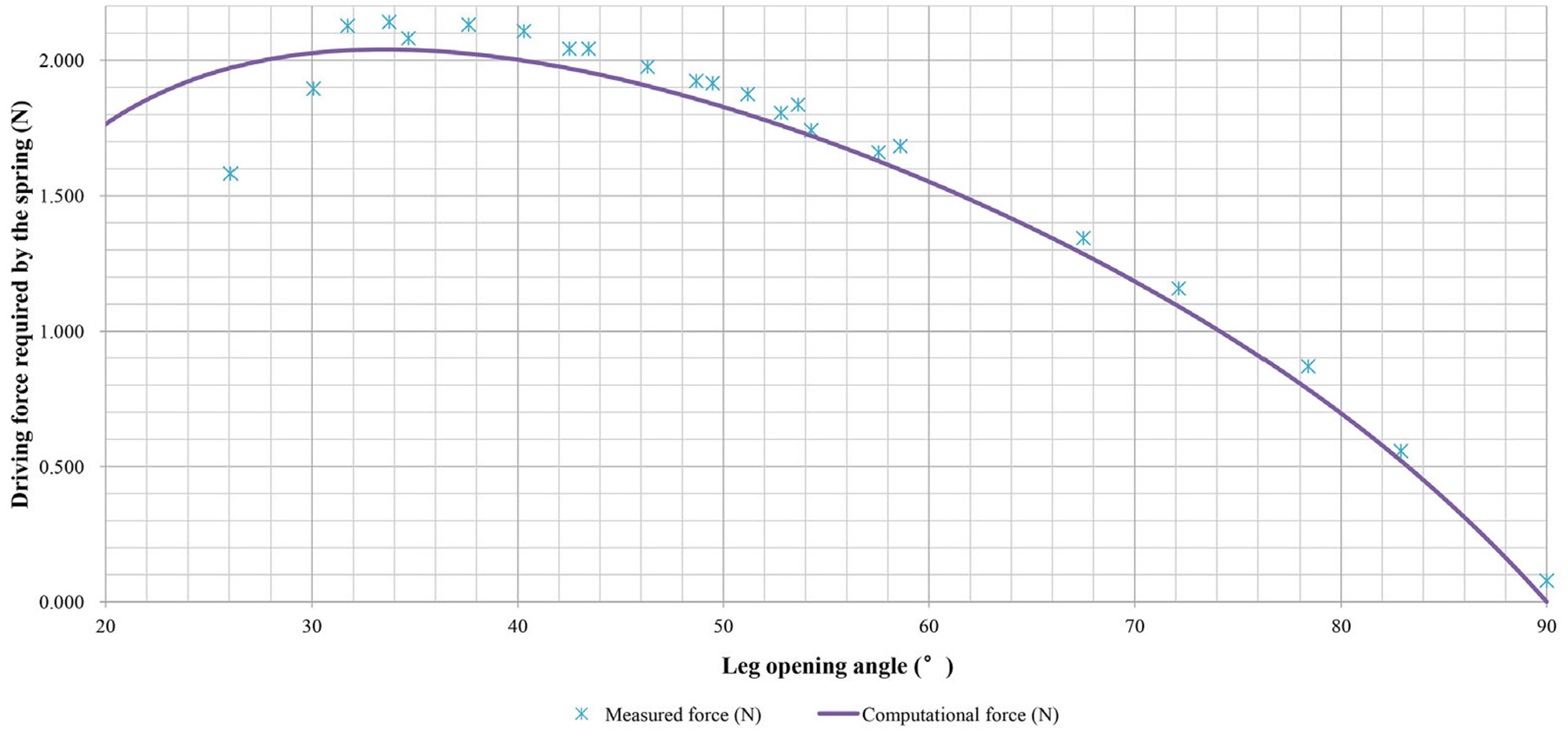
Comparison of the calculated and experimental driving force values (kS = 0.06 N/mm and LS0 = 7 mm).
Driving force from the internal motor
In this experiment, a set of springs with a stiffness of approximately 0.06 N/mm (kS = 0.06 N/mm) and an original length of approximately 7 mm (LS0 = 7 mm) was again employed in the CR. The spring-connected legs were successfully stretched out by the internal motor (Video).
Discussion
Figure 8 shows that when the leg angle α was less than approximately 30°, the measured values were lower than the calculated values. The reason for this anomaly is that under this condition, the springs were at least partially in contact with the CR shell and formed a nonhexagonal shape, ultimately leading to a lower force. When the leg angle α was larger than approximately 30°, the measured values were always slightly higher than the calculated values. The reason for this difference is probably that errors were inevitably introduced in this test from the measurement of the nut movement distance with the Vernier caliper and the friction between the external moving rod and its support. Nevertheless, the trend of the measured values is quite consistent with the trend of the calculated values. Both the calculated and measured values show that the thrust required on the nut reaches its maximum near a leg angle of 33° (LS0 = 7 mm) and that in the vicinity of a leg angle of 90°, the thrust required on the nut is almost 0, while the spring extension reaches its maximum.
Although the structural parameters of the CR are determined values, there is still some room for variation and selection of the spring parameters to exert a desired effect on the driving force FN.
The influence of the spring stiffness kS on the driving force FN is unambiguous, but the appropriate stiffness depends on whether the CR is to be used for drug delivery, biopsy, or stagnation inspection and will require further study.
The initial spring length LS0 also has a significant effect on the driving force FN. The arc length on the outer circle (DCE = 16 mm) of the capsule shell between two adjacent legs (with a total of n = 6 springs) is approximately 8.38 mm. This means that the center distance between the hooks at both ends of the spring is no greater than 8.38 mm when the spring is in its initial nonextended state. From (8), it can be seen that decreasing the initial spring length LS0 will increase the driving force FN.
By reducing the initial spring length LS0 from 8.38 to 7 mm, the leg rotation angle corresponding to the maximum value of the driving force FN is decreased from 43° (Figure 6) to 33° (Figure 8). The influence of this parameter on the peak moment of the driving force may be used in future studies to determine the relative length of each rod.
In addition, the structure may be improved to allow the springs to be embedded in the body of the CR in the initial state.
Conclusion
This paper proposes a novel CR with spring-connected legs. Based on the design and fabrication of the CR, the driving force on the internal nut required for the stretching of the springs has been both theoretically analyzed and experimentally measured. The calculated and measured data are graphically displayed for comparison to validate the analysis of the driving force. The driving force provided by the internal motor has been calculated and experimentally validated to be greater than the driving force required by the springs, which indicates that the proposed CR with spring-connected legs has the potential to be further developed into a more compact device to meet the size requirements of clinical applications.
Footnotes
Appendix
Handling Editor: Chenhui Liang
Declaration of conflicting interests
The author(s) declared no potential conflicts of interest with respect to the research, authorship, and/or publication of this article.
Funding
The author(s) disclosed receipt of the following financial support for the research, authorship, and/or publication of this article: This work was supported by the Natural Science Foundation of Fujian Province (no. 2018J01643) and the Scientific Research Fund of Fujian Provincial Education Department (no. JAT170193).
Supplemental material
Supplemental material for this article is available online.
References
Supplementary Material
Please find the following supplemental material available below.
For Open Access articles published under a Creative Commons License, all supplemental material carries the same license as the article it is associated with.
For non-Open Access articles published, all supplemental material carries a non-exclusive license, and permission requests for re-use of supplemental material or any part of supplemental material shall be sent directly to the copyright owner as specified in the copyright notice associated with the article.