
Abstract
In order to reduce and control the generation and development of early cracks in the concrete utility tunnel, ABAQUS finite element software was used to model the temperature field and thermal stress of early-age concrete of a thin-walled box structure. For the accuracy of simulation, the hydration heat of cementitious materials was tested by TAM air method, and the actual working conditions were used. Different curing methods were modeled, such as formwork type, formwork removal time, and curing time. Simulation results showed that steel formwork shall be selected for construction in summer, and the recommended formwork removal time was 3 days, which was better to resist temperature induced cracks. Moreover, the sooner the formwork was removed, the smaller temperature difference between concrete surface and center, but it would bring difficulties to the cooling rate control. Also, higher temperature occurred at bottom plate, especially in the junction area between bottom plate and partition wall. The maximum thermal stress was found at the junction between top plate and partition. Last but not lease, attention should be paid to the occurrence of peak temperature in 26 h, temperature difference control for 26–50 h, and cooling rate control during 2–5 days.
Keywords
Introduction
The utility tunnel, also known as underground pipeline colligate alure in city, is a passage built underground to carry municipal utility lines including electricity, water and sewer pipes, etc. China has vigorously promoted the construction of such tunnels. Currently, total mileage of utility tunnels in China has exceeded 2000 km, 1 which is expected to increase to tens of thousands of kilometers in near future. The utility tunnel often adopts thin-walled box structure, and how to control its cracking has always been one of the difficulties hindering its development. Numerous projects have reported obvious slightly inclined vertical cracks on the surface of the external wall, 2 and 0.1–0.3 mm wide vertical cracks on the side wall every 2–3 m, 3 which seriously affects the durability and use function of tunnels.
Present research on the concrete structure of utility tunnels mainly focuses on the shrinkage cracks and structural mechanical properties of concrete. Among them, Parsajoo et al. 4 emphasized the importance of tensile strength on in the design of tunnels and explored ways to measure tensile strength of rock material using non-destructive tests. Xia et al. 5 analyzed the influence of geotextile, shrinkage reducing agent, and other maintenance methods on the shrinkage cracking of utility pipes. Hu and Xue 6 conducted the repeated load test on a full-scale model of the joint to evaluate the seismic behaviors and safety of bottom nodes and middle nodes of a cast-in-situ composite slab tunnels. Wang et al. 7 numerically studied the stress distribution and the deformation of utility tunnel by extracting the stress value of the nodes at the joint and the cracking load of the utility tunnel was determined. However, the early cracks of the thin-walled box concrete structure such as utility tunnels during construction stage is caused by (1) temperature, (2) huge temperature differentials between center and surface temperature difference, and (3) excessive cooling rate. 8 Therefore, temperature control methods should be detailed in the construction plan of utility tunnels.
Researchers at home and abroad have been studies the temperature induced cracks in mass concrete extensively. Leon and Chen 9 analyzed the influence of mix proportion of mineral powder on concrete temperature time history and temperature stress. Wang et al. 10 found that the adiabatic temperature rise can be reduced by 6.07°C with compound admixtures. When the molding temperature could be reduced by 10°C, the temperate differential between center and surface could be reduced by 4.26°C. Shu and Xia 11 took the anchor splay saddle of Lijiang bank tunnel of Jin’an Jinsha River Bridge as an example to carry out the mix proportion optimization design of mass concrete. Taking the main channel bridge of Hutong Yangtze River Bridge as the research object, Xu et al. 12 determined the proportions of cement hydration control materials and composite expansion materials with isothermal calorimetry and variable temperature deformation tests. The peak center temperature of optimized concrete decreased by 6.4°C, the expansion deformation more than doubled while the shrinkage deformation decreased by 100 με. Zhou and Liu 13 believed that grounded copper slag was similar to fly ash, which can reduce hydration heat release rate and adiabatic temperature rise, and therefore could be used as admixture for mass concrete. Bourchy et al. 14 determined the composition of concrete and the amount of auxiliary cementitious materials after comprehensively reviewed the mechanical properties and hydration heat of concrete. Qi 15 studied the influence of pouring thickness on temperature change. The results showed that the greater the pouring layer thickness, the higher the temperature rise would be, the later the temperature peak would appear. Su 16 used Midas simulation to analyze the hydration heat effect of an underwater pier cap of a arch bridge, and he believed that the hydration heat temperature and stress can be effectively reduced by adopting layered pouring and controlling the molding temperature. Tasri et al. 17 adopted finite element simulation to analyze temperature variation and stress field in mass concrete which used cooling pipes to control temperature increasing.
Clearly, research on temperature induced cracks of mass concrete mainly focused on concrete mix proportion and other materials. But there is little report on the key parameters and construction scheme affecting temperature, Therefore, it is an area deserve systematical and in-depth studies. 18 What’s more, the studied mass concretes are mainly used in structures such as high-rise building foundation, bridge bearing platform and pier body, water conservancy dam, etc., and there is few studies cared about thin-walled concrete structures for utility pipes. The characteristics of these two structures are different, resulting in different degrees of restraint, stress distribution, and development. Therefore, there is a need to systematically study the factors affecting the cracking of utility tunnels in the construction process considering its construction environment and structural characteristics.
To provide insights for reducing and controlling the generation and development of early cracks in utility tunnels, this paper will carry out simulations to study the impact of maintenance methods (e.g. formwork type, removal time, curing time) on internal temperature field and thermal stress of thin-walled box concrete structure, taking Tongtu Road Comprehensive Pipe Gallery Project as an example. During simulations, construction environment and structural characteristics will also be taken into account. So, to realize transient modeling of temperature load variation, environment temperature change, and define the relationship between concrete constitutive (elastic modulus) and aging, several user-defined subroutines HETVAL, USDFLD, FILM, UMAT have be developed on ABAQUS secondary development platform with FORTRAN.
Heat transfer mechanism
Heat conduction
At any point in the concrete, the unstable temperature field must meet the heat conduction equation (equation (1)):

Where,
T = temperature;
λ = thermal conductivity;
c = specific heat of material;
Q = heat release rate of concrete;
T = time;
ρ = density.
Under adiabatic conditions, temperature rise of concrete comes from the internal hydration heat. Therefore,

The degree of hydration is the degree of hydration reaction of cementitious materials in concrete at a certain age. The degree of hydration

Where:
Q(t) = the hydration heat release at the age t per unit mass of cementitious material;
Q max = the heat release when the unit mass cementitious material is completely hydrated;
q(t) = the hydration heat release rate;
t = time.
Therefore, the heat release rate of concrete at a certain time can be expressed as

Thermal stress
According to the basic theory of temperature field of finite element method, the temperature field distribution T can be solved.
For isotropic elastomer, the thermal expansion coefficient is the same in X, Y, and Z directions, and temperature linear strain and temperature shear strain can be expressed by the following formula:


Where, εx, εy, and εz are the temperature linear strain in the X, Y, Z directions, and γxy, γyz, and γxz are the temperature shear strain in the directions XY, YZ, and ZX, respectively.
The displacement vectors of all nodes of the element e are:

Then the displacement of any point in the element can be expressed by

Where, N is the shape function matrix.
For isotropic elastomers, the stress-strain relationship can be determined by the generalized Hooke’s law, which is expressed as follows:

Where, {ε0} is its initial strain, {σ0} is the initial stress, [D] is the elastic matrix.
Then the element force at each node can be expressed by the following formula:

Where [k]e it is called the element stiffness matrix.
The joint load caused by the initial stress and strain of the joint can be calculated by

From the node balance equation:

Where, [K] is the overall stiffness matrix of the structure, and the elements in [K] can be expressed as kij, that is

After meshing of the structure, the corresponding shape function equation and single element stiffness matrix will be established. For the same node, these elements will be superimposed and combined to obtain the overall stiffness matrix. Combining stiffness matrix, displacement matrix and load matrix, the overall equilibrium equation is established, and the final result is temperature stress.
Finite element model
Project overview
The open cut cast-in-situ Tongtu Road Utility Tunnel starts from the intersection of Tongtu Road and Qingshuiqiao Road, stops at Tongtu Road and Century Avenue in the west, and intersects Xinhui Road in the north. The net widths of the two tanks of the tunnel are 2.8 and 2.6 m respectively, and the net height is 3.1 m. The thickness of the upper and lower layers of tunnel, as well as two external walls are 350 mm, and the partition between the two tanks is 250 mm, as shown in Figure 1.
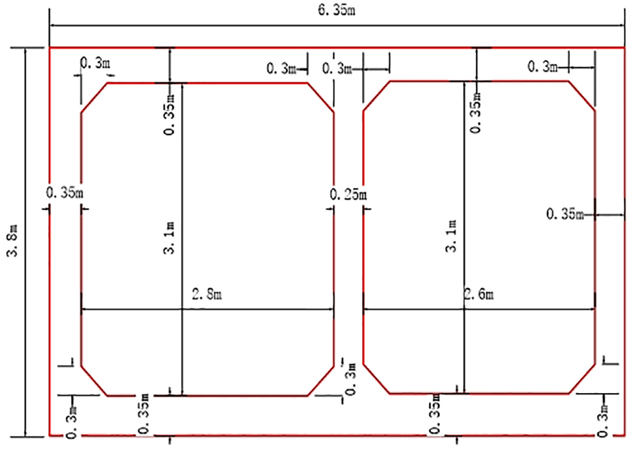
Sectional dimension of utility tunnel.
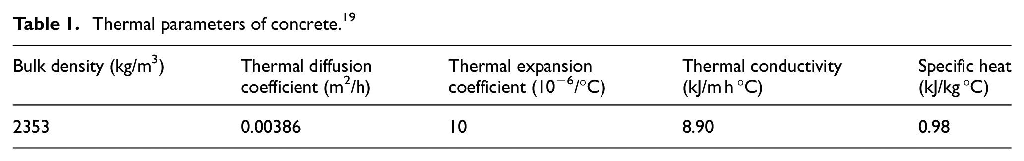
C40 concrete was adopted for the this project, and its ratio was P.O42.5 ordinary Portland cement:Grade II coal ash:S95 slag powder:sand:gravel:water:water reducer (polycarboxylic acid superplasticizer) = 256: 81:112:640:1089:175:8.08. The thermal and mechanical parameters of concrete are listed in Tables 1 19 and 2 respectively.
Thermal parameters of concrete. 19
Mechanical parameters of concrete.

During construction, the environment temperature ranged from 37.7°C to 19.3°C. The pipe gallery concrete was poured twice. The bottom plate and 500 mm above it was poured first, followed by side walls and top plate. The formwork were removed in 3 days and maintained with water curing and geotextile for 14 days.
Mathematical modeling
ABAQUS finite element modeling was used to model the targeted utility tunnel (as shown in Figure 2), whose early temperature field and thermal stress of were simulated and analyzed. Hydration heat release rate and cumulative heat release rate of cementitious materials measured by TAM air isothermal calorimeter were converted in to heat flux variation with time and integrated into modeling using HETVAL, USDFLD subroutines. Elastic modulus variation with age was defined by equation (12) 20 and integrated into model by UMAT subroutine. Concrete tensile strength with time is taken as 21 according to equation (13).


Where:
E 0 = final elastic modulus, a constant, MPa;
τ = age, days;
E(τ) = elastic modulus value varying with age, MPa;
R f0 = 28 days tensile strength, MPa;
R f(τ) = tensile strength at different ages, MPa.

Finite element model.
In order to verify the accuracy of temperature field simulation, simulation result of adiabatic temperature rise was first simulated and compared with measured data according to the cumulative heat release test value and the hydration adiabatic temperature rise formula in equation (14). The comparison in Figure 3 proved that the simulation results fitted well with measured date. The simulated temperature rise is 41.45°C, the measured temperature rise is 42.41°C, and the difference between the two was 0.96°C (error percentage 2.26%), indicating that the temperature field simulation method was accurate and reliable.

Where:
Q(τ) = the measured value of cumulative hydration heat release at age, kJ/kg;
W = cement dosage, kg;
k = the reduction factor;
F = weight of mixture, kg;
c = the specific heat of concrete, kJ/(kg °C);
ρ = the concrete density, kg/m3.

Temperature rise curve of simulation result and calculation result.
Boundary condition
The initial temperature of concrete is assumed to be the same as the molding temperature and temperature distribution is uniform. For the boundary conditions, the bottom, which contacted with the foundation was set as adiabatic. Before formwork removal, the boundary condition was set as thermal convection boundary between smooth formwork surface and air. After removal, it was the thermal convection boundary between smooth concrete surface and air. For geotextile water cured surface, it is the thermal convection boundary between concrete surface and flowing water, which belongs to the 3rd type of thermal boundary conditions. So, the boundary conditions are related to the type of formwork and maintenance method. The surface heat dissipation coefficient βs was used in the simulation, which value can be calculated by equation (15), and the results are shown in Table 3.

Where:
β = thermal diffusion coefficient;
h i = thickness of formwork or insulation layer;
λ i = thermal conductivity of the template.
Heat dissipation coefficient under different boundary conditions (kJ/m h °C).

Modeling setup
Table 4 listed some typical working conditions used for this simulation analysis.
Summary of working conditions.

During construction, environment temperature is one of the factors that directly affect the concrete temperature field and thermal stress. Combined with the meteorological data of Ningbo, the cosine function with a period of 24 h was developed to simulate the daily change of air temperature. The specific formula for the calculation of ambient temperature is as follows:

Where:
i = concrete age, h;
T max = daily maximum temperature, °C;
T min = daily minimum temperature, °C.
The environment temperature variation was cooperated into modeling via FILM subroutine. The simulated value is compared against the calculated value of the cosine function. As shown in Figure 4, it is clear that the simulated environment temperature of tunnel is consistent with the cosine function.
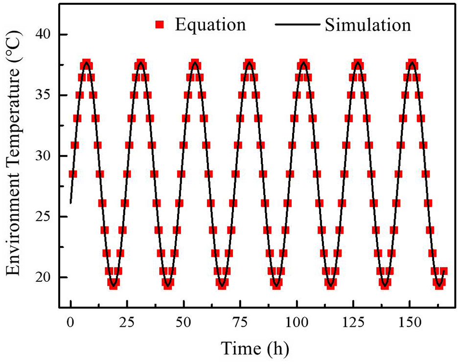
Environment temperature modeling.
Result
This section presented simulation results for different curing methods, that is material of formwork, removal time, and maintenance method by comparing their thermal stress and temperature profiles.
Formwork material
Three most common materials for formwork are steel, wood, and foam plastic. Figure 5 compared 7 days temperature and thermal stress of concretes with different formwork materials.

Temperature and thermal stress of concrete utility tunnel with formwork materials: (a) temperature field and (b) temperature stress.
Figure 5 demonstrated temperature and thermal stress of concrete utility tunnel with formwork materials. Higher temperature at the bottom plate were witnessed for all cases, especially at the middle sections of bottom plate, middle section of partition, and joints of bottom and partition. Temperature would gradually decrease to surroundings, and the lowest temperature was witnessed at the external surfaces of the top plate and bottom plate. The highest thermal stress appeared at the outside surface of connections between top plate and partition, as well as the corner of the bottom plate. The peak inside temperature was the highest with foamed plastic board (51.68°C), followed by wood (48.09°C) and steel (45.22°C) in a decreasing order. Similar trend was witnessed in thermal stress, the recorded peak thermal stresses for foamed plastic, wood, and steel were 2.379, 2.126, and 1.830 MPa, respectively.
Temperature profiles at the center of top plate and bottom plate were shown in Figure 6. The center temperatures of concrete top plate peaked at 41°C, 42°C, and 43V with steel, wood, and plastic foam, respectively, while the center temperatures of bottom plate peaked at 44°C, 47°C, and 52°C with steel, wood, and plastic foam. For both plates, the time to reach peak temperature was the shortest with steel and the highest with plastic foam. After formwork had been removed, temperature of top plate dropped at 3.1°C/days (steel), 4.7°C/days (wood), and 6.2°C/days (plastic foam) and the bottom plate at 2.4°C/days (steel), 3.3°C/days (wood), and 4.2°C/days (plastic foam), respectively.

Temperature at the center of top plate/bottom plate of concrete utility tunnel model under different formwork: (a) top plate and (b) bottom plate.
Figure 7 showed temperature differential between concrete center and surface of bottom plate. According to the chart, the temperature differential was highest for plastic foam board, followed by wooden and steel, in a decreasing order. The maximum temperature differentials were all greater than 25°C except steel formwork. However, temperature differentials were all stabilized gradually with the increase of age.
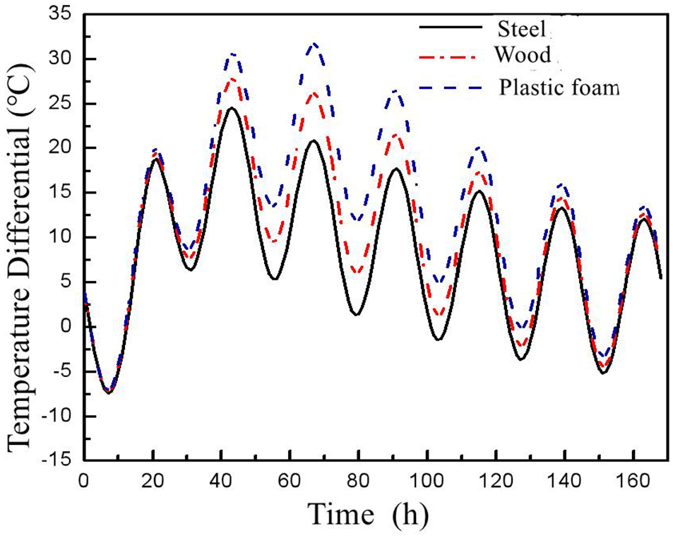
Temperature differential in the bottom plate of pipe gallery under different formwork.
Formwork removal time
The formwork removal time has a great impact on the risk of concrete cracking. GB50666 Code for Construction of Concrete Structure clearly states that the removal time of formwork should be decided based on strength requirements and temperature control requirements, but the code does not give the specific removal time. Remove formwork too early will cause cracks in the surface of concrete due to the adverse impact of the temperature difference between day and night. However, remove formwork too late is likely to cause cracks at the surface due to additional deformation constraints. Therefore, the influence of formwork removal time on the concrete temperature and thermal stress of the utility tunnel was analyzed. The results are shown in Figure 8.
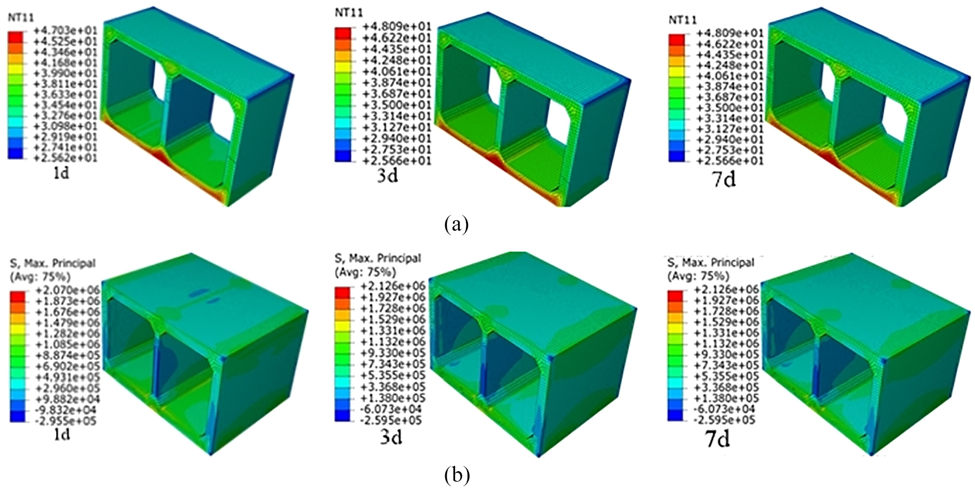
Temperature field and thermal stress of concrete utility tunnel at different formwork removal times: (a) temperature field and (b) thermal stress.
With the delay of formwork removal, temperature and thermal stress of concrete utility tunnel increased gradually (Figure 8). When the formwork was removed at 1, 3, and 7 days, the peak temperature of mass concrete was 47.03°C, 48.09°C, and 48.09°C, and thermal stress was 2.07, 2.126, and 2.126 MPa respectively.
Further studies on central temperature profiles of top and bottom plates with different formwork removal times were shown in Figure 9. The shorter the formwork removal time was, the faster temperature drop would be. The influence of formwork removal time gradually decreased with the increase of concrete age, and finally all temperature tended to be the same. At cooling stage, top plate was cooled at a faster rate than that of the bottom plate, and reached temperature equilibrium earlier. Cooling rate of top and bottom plate was 0.14°C/h (3.47°C/days) and 0.083°C/h (2°C/days), respectively. Thermal equilibrium was reached at about 120 and 240 h for top and bottom plate.

Temperature at the center of top plate/bottom plate of concrete utility tunnel model under different formwork removal time: (a)top plate and (b) bottom plate.
Figure 10 shows the temperature differential of bottom plate. When the removal time was 1, 3, and 7 days, the temperature difference was 24.9°C, 26.7°C, and 26.8°C respectively.

Temperature differential in the bottom plate of pipe gallery under different formwork removal time.
Maintenance method
In order to study the influence of different curing methods on the concrete, 7 days temperature and thermal stress of tunnel were simulated. The two selected methods were geotextile + water curing and direct exposure. The results were shown in Figure 11. The maximum thermal stress of concrete was 2.1 and 4.2 MPa when concrete was directly exposed to air and geotextile + water cured, respectively.

Temperature field and thermal stress of concrete utility tunnel under different curing methods: (a) temperature field and (b) thermal stress.
In order to further analyze the influence of different curing methods on the temperature change of concrete, temperature profiles of top and bottom plates were generated in Figure 12. Under the same maintenance method, the temperature of the top plate was more sensitive to environment change than bottom plate. Also, temperature of concrete varied significantly when it was cured with geotextile + water. So did the cooling rate.

Temperature at the center of top plate/bottom plate of concrete utility tunnel model under different curing methods: (a) top plate and (b) bottom plate.
Figure 13 illustrated the effect of maintenance method on the temperature difference between surface concrete and center of bottom plate. For both methods, temperature differential exceeds the recommended temperature difference limit of 25°C. However, geotexile + water could significantly reduce temperature difference.
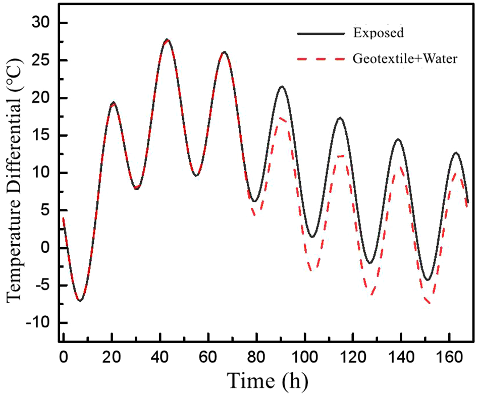
Temperature differential in the bottom plate of utility tunnel under different curing methods.
Discussion
Formwork material
The impact of formwork materials on temperature and thermal stress were presented in Figures 5 to 7. It was obvious that different material had impact on peak temperature, peak temperature onset, thermal stress, and cooling rate. The highest peak temperature and thermal stress were found with foam plastic formwork, followed by wood and steel in a decreasing order. Probably because the heat dissipation coefficient of the steel was greater than that of the wood and foam plastic, allowing heat to be released easily. Foam plastic has the lowest heat dissipation coefficient, so heat likely built up in concrete and therefore a higher peak temperature.
At the cooling stage, temperature of plats dropped gradually. Bottom plate exhibited a slower cooling rate compared to that of top plate. Different formwork materials affected cooling rate differently. The highest cooling rate was witnessed with foam plastic board. But no mater which material was used, the cooling rates of concrete all exceeded the standard cooling rate (2°C/days). It is thus necessary to enhance heat release when heat is building up, and control heat release rate during the cooling stage to avoid excessive cooling rate, especially for wood and foam plastic in case of temperature induced cracks caused by excessive cooling rate and large temperature differential after formwork was removed.
Formwork removal time
Figures 8 to 10 compared the impact of formwork removal time. During the construction in summer, the excessive temperature difference between surface concrete and center would be likely to occur if the formwork removal time was prolonged. In addition, the earlier formwork was removed, the lower peak temperature and corresponding thermal stress the mass concrete would presented. Yet, when the formwork removal time was longer than 3 days, temperature and thermal stress had no obvious change. It could be explained by the fact that the temperature of concrete is mainly dominated by hydration in the early stage, and environment temperature at later stage. Therefore, there is no significant difference in temperature field or thermal stress between removal time of 3 and 7 days.
Maintenance method
The impact of curing method was explored in Figures 11 to 13. As shown in these figures, the curing method had little impact on the maximum temperature inside the concrete, but had a great impact on the thermal stress. It is probably because that water poured on top of concrete had a lower temperature than air, and the heat dissipation coefficient of geotextile was much higher than that of concrete exposed to air, which enhanced the heat transfer. As a result, a large temperature difference between surface concrete and center was produced and corresponding thermal stress.
Conclusion
This study aimed to investigate the generation and development of early cracks in the concrete utility tunnel using ABAQUS. For the accuracy of simulation, real material setting and boundary conditions were used. Results showed that steel formwork had its advantage at resisting temperature induced cracks in summer, after comprehensively reviewing the impacts of temperature, thermal stress, maximum temperature differential, and cooling rate. Moreover, formwork removal time would affect temperature differential between concrete surface and center, as well as the cooling rate. Removing formwork earlier would help to control the temperature of mass concrete, but it would affect cooling rate negatively. After balancing the thermal tress of material, working intensity and turnover requirements in the actual project, the formwork removal time of 3 days was recommended. What is more, maintaining with geotextile and water curing would help to increase concrete cooling rate and concrete stress field in turn. Also, in order to reduce and control the generation and development of early cracks in concrete utility tunnels, special attention should be paid to the heat built-up inside the concrete at 26 h, especially tin the junction area between bottom plate and partition. Temperature differential between concrete surface and center at 26–50 h should be closely monitored, as well as the cooling rate inside the concrete at 2–6 days. In conclusion the study has investigate the generation and development of early cracks in summer under different curing methods. There is however the need for further studies on generation of early cracks in winter. Also, if stratified placement would help to control crackings in mass concrete worth exploring.
Footnotes
Handling Editor: Chenhui Liang
Declaration of conflicting interests
The author(s) declared no potential conflicts of interest with respect to the research, authorship, and/or publication of this article.
Funding
The author(s) disclosed receipt of the following financial support for the research, authorship, and/or publication of this article: Authors would like to acknowledge the funding form National Natural Science Foundation of China (No. 51569035), “Innovation 2025” major project of Ningbo (No. 2020Z056), major key social development project of Ningbo Science and Technology Bureau (No. 2017C510007).