
Abstract
Although accurate intracranial pressure (ICP) monitoring is essential for the diagnosis and treatment of severe brain diseases, current methods are performed invasively. Therefore, a safe and less invasive ICP measurement is required. The purpose of our study was to develop a simplified cranial cavity model for a better understanding of the relationship between the ICP and the pressure measurement within the dural venous sinus (DVS) to support the validity of using sinus pressure as the surrogate of the ICP. The in-house cranial cavity model had three components: the brain part, the DVS part, and the subarachnoid space (SAS) part. Pressure in other parts was measured when the pressure in the SAS part and, separately, brain part was increased from 0 (baseline) to 50 mmHg at intervals of 10 mmHg. When the pressure in the SAS part was increased from 10 to 50 mmHg at 10 mmHg interval, pressures of both the brain and DVS parts increased without significant difference (all P > 0.05). However, pressures in both the SAS and DVS parts differed while the pressure in the brain part was increased. The pressures in both parts showed about 70% of the increase in the brain part. Nevertheless, the pressures in the SAS and DVS parts were not significantly different (P > 0.05). A simplified in-house cranial cavity model was developed consisting of three compartments to represent the actual intracranial spaces. The pressure measurement within the DVS was feasible to use as a surrogate for the ICP measurement.
Introduction
Measurement and monitoring of the intracranial pressure (ICP) are essential for the diagnosis and management of various neurocritical conditions. 1 The current reliable methods of ICP monitoring are performed invasively requiring burr-hole craniostomy. 2 Even though placing an intraventricular catheter can immediately reduce the increased pressure by drainage of the cerebro-spinal fluid (CSF), 3 monitoring the ICP with a less invasive method is one of the dire unmet clinical needs in the management of the various conditions of increased ICP.
According to the Monro-Kellie doctrine, the pressure in the closed intracranial space should be the same since the volume sum of the intracranial contents are constant. 4 Based on this theory, we hypothesized that the pressure measured in the dural venous sinus (DVS) may reflect the ICP especially when the pressure is increased. Successful demonstration of the coupling between the pressures measured in the superior sagittal sinus and CSF space may support the hypothesis.5,6 The pressure measured in the DVS could be a practical surrogate reflecting the ICP. For the initial proof of our concept, we devised a simplified cranial cavity model consisting of the rigid skull, the soft brain parenchyma, and the tubular DVS within the subarachnoid space (SAS) filled with the CSF.
The purpose of this simple experiment was to develop a simplified cranial cavity model for a better understanding of the relationship between the ICP measured in the SAS and the pressure measured in the DVS.
Materials and methods
Cranial cavity model
In the replication of the real cranial cavity (Figure 1(a)), we devised a transparent in vitro model as simple as possible having three major intracranial components (a rigid skull part, the DVS part, and a brain part) (Figure 1(b)). The brain part and SAS part were filled with saline and externalized with a short tube. Each end of the DVS part was connected to the closed fluid circuit maintained by a peristaltic pump to replicate the venous blood flow.
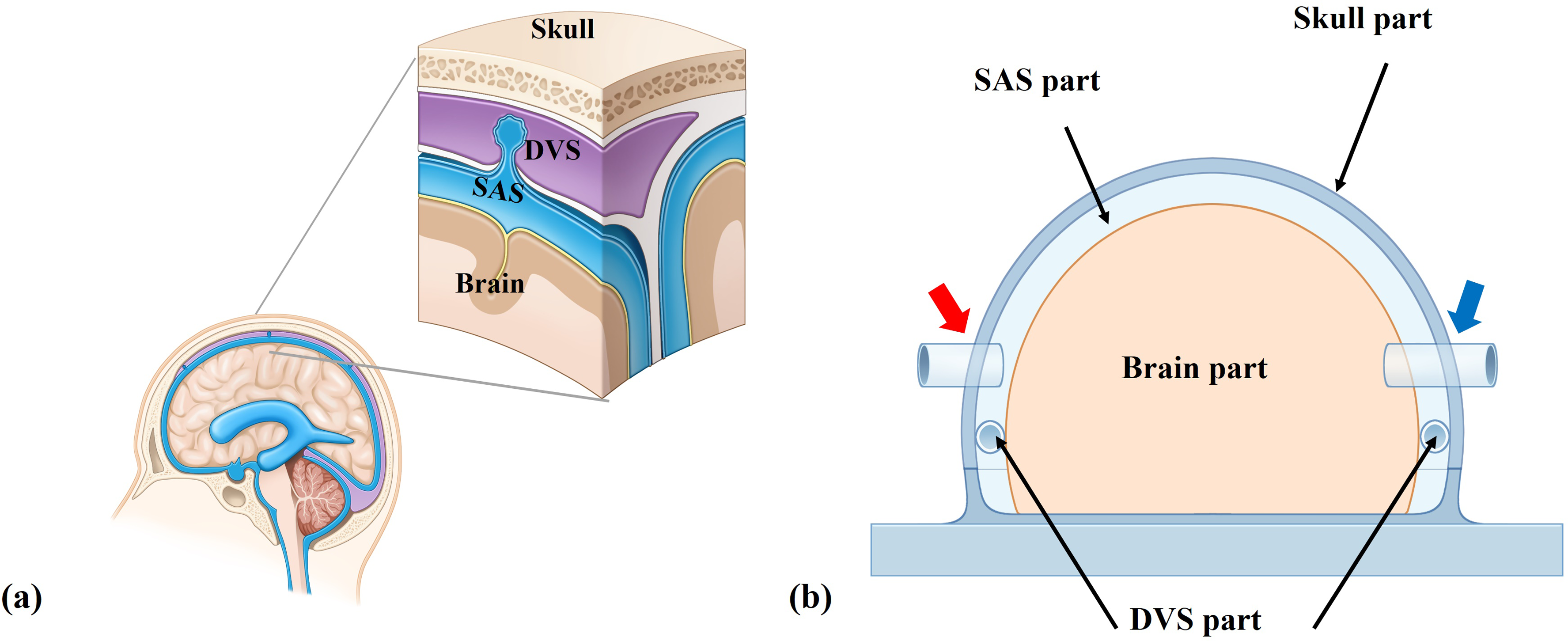
Schematic representations of a real cranial cavity and an in vitro model. (a) A magnified image of the intracranial cavity. There are two parts between the rigid skull and the brain parenchyma. The cerebrospinal fluid (CSF) flows from the subarachnoid space (SAS) to the dural venous sinus (DVS) via arachnoid granulation. (b) A simplified in vitro model reflecting real cranial cavity. The model was designed to implement the DVS part and the SAS part between the brain part and rigid skull part. It was also fabricated to enable the pressure increase by injecting the saline through two tubes which were connected in the SAS part (red arrow) and the brain part (blue arrow) on both sides of the model.
Brain part
The brain part was made in a semi-oval shape and the specific dimensions are 130 mm in width, 210 mm in length, and 93 mm in height (Figure 2(a)). A soft silicone material (SORTA-Clear™ 12; Smooth on, East Texas, USA) was used for fabricating a hollow brain part with a thick wall to replicate the human brain compliance. Since human brain compliance is between 0.7 and 0.8 on average, the wall thickness was determined to reflect this.7,8 The brain part was connected to a tube on one side of the dome in the skull part to enable the ICP measurement by controlling the amount of saline inside the brain part with checking the mechanical manometry to replicate the increased ICP circumstance in brain parenchyma.
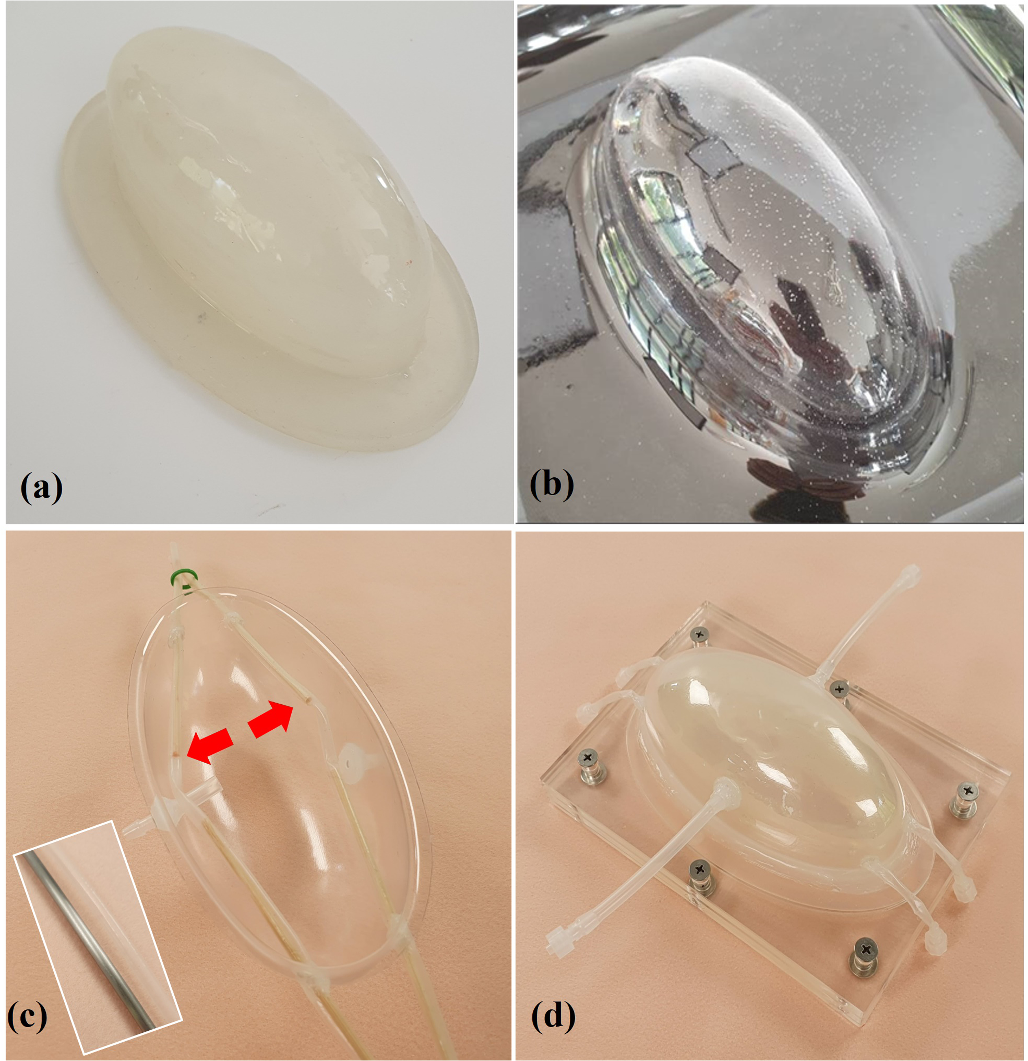
The in-house model fabricating process. (a) A semi-oval shape of the brain part. (b) The process of shaping the solid and transparent skull part. (c) A skull part had the same shape as the brain part connecting the DVS part (red arrow). (d) The fully combined simplified cranial cavity model.
Skull part
The skull part was also fabricated in the same semi-oval shape as the brain part and was made of polyethylene terephthalate materials (Pet sheet; Hengshui Jizhou Qinghua Plastics Factor, Hebei, China). This material made the skull part hard and transparent to allow observation of internal manipulations. The specific dimensions were 73 mm in width, 151 mm in length, 60 mm in height, and 0.8 mm in thickness (Figure 2(b)). At each side of the dome, we created a hole to externalize the skull part and the brain part. By connecting a three-way stopcock, we could pressurize each part by infusing saline using a syringe and measure the pressure with a mechanical manometer (NO 500; Kenzmedico, SAITAMA, Japan) (Figure 2(c)).
Dural venous sinus (DVS) part
We created a pair of DVS parts, each of which was a silicone tube that had an inner diameter of 4 mm and a wall thickness of 0.2 mm (Figure 2(c)). The thin tube was fabricated by multiple layering of liquid silicone (Psycho paint; smooth-on, USA) for sufficient mechanical strength. 9 The DVS part was placed along the lateral inner border of the skull part and fixed within the SAS part. The DVS part was inserted into the closed fluid circuit. A 0.027-inch microcatheter (Prowler Plus; Cerenovus, Miami, USA) was placed via the circuit and the tip was placed in the middle of the DVS part while the fluid-flowing circuit was maintained using a peristaltic pump (Ecoline VC-380; ISMATEC, Wertheim, Germany).
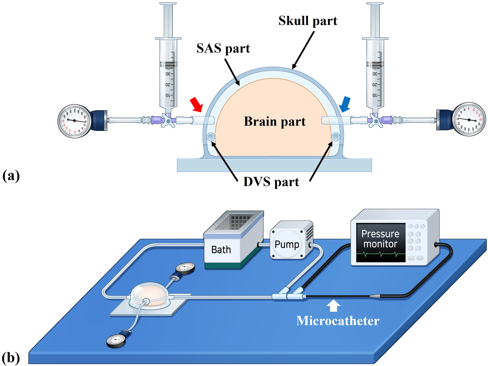
Schematic illustrations of the model assembly and experimental design. (a) A syringe and mechanical manometer were connected to the SAS part (red arrow) and the brain part (blue arrow), respectively. The pressure within the DVS part was measured with the 0.027-inch microcatheter. (b) The closed-circuit platform with a peristaltic pump, pressure monitor, and in vitro model.
SAS part and the model assembly
The assembled model had three spaces: in the brain part, the DVS part, and the SAS part (Figure 2(d)). We could increase the pressures of those spaces by manual injection of saline using a syringe via the tubes connected to the brain part and the SAS part (Figure 3(a)). We could control the injection by monitoring the pressure using the connected mechanical manometer. The syringes and mechanical manometers were connected on both sides simultaneously using a three-way stopcock (Figure 3(a)). The assembled model was connected to the closed fluid circuit via the silicone tube of the DVS part (Figure 3(b)). A constant but minimum flow was maintained by setting the peristaltic pump at 7 rotations per minute (rpm) to minimize any influence from the flow in the circuit. To check the characteristics of the assembled model, the volumes of saline infused into the brain part and the SAS part were measured, respectively. The compliances of each part were calculated using the following formula: compliance = infused saline volumes / the target pressure. 10
Experimental design
To simulate two different sources of increased ICP, the pressures in the SAS part and brain part were increased gradually (0, 10, 20, 30, 40, 50 mmHg). While the pressure in the SAS part was increased, we measured the pressures in the brain part and the DVS part. When the pressure in the brain part was increased, we measured the pressures in the SAS part and the DVS part. Each measurement was repeated four times.
All statistical analyses were performed using SPSS software (version 24.0; IBM, Armonk, NY). Wilcoxon signed-rank test (non-parametric method) was utilized to compare the pressure changes. All P values were two-sided; a value less than 0.05 was considered statistically significant.
Results
The characteristics of the model
We required 250 mL and 90 mL of saline to fill the brain part and the SAS part, respectively. In the closed fluid circuit, 7 rpm was equivalent to 20 mL/min in our simulation environment. On visual inspection of the model, there was no significant fluid leakage at the connecting parts of the model during pressurization of each part.
The mean compliance of the whole rigid skull part was calculated as 0.19 while that of the brain part itself was 0.75 (online supplementary material).
Pressure response of the DVS part to the increased pressures
When the pressure of the SAS part was increased from 0 to 50 mmHg, the pressures of the brain and DVS parts increased without any significant pressure difference (Table 1, Figure 4). Especially, there were no statistically significant differences between the brain part and the DVS part while reflecting all increased pressures of the SAS part (P > 0.05).
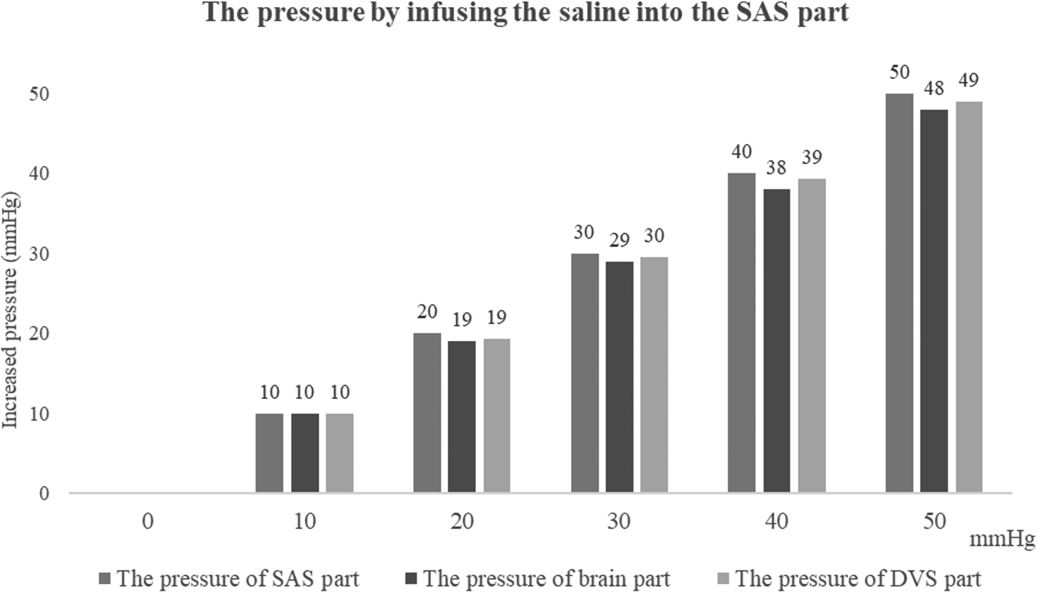
The mean values of the increased pressures in the brain part and the DVS part by infusing the saline into the SAS part.
Pressure change according to step wise pressue increase in SAS part.
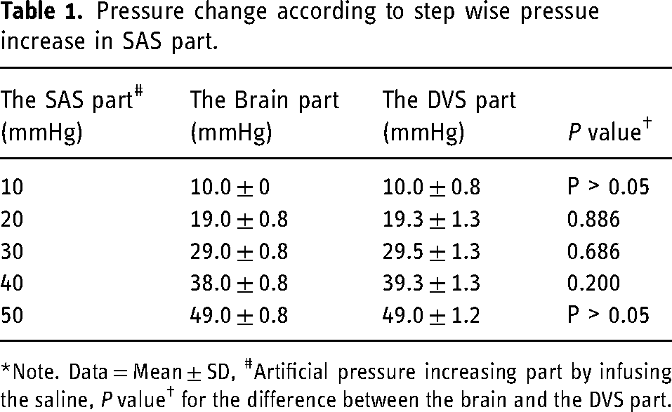
*Note. Data = Mean ± SD, #Artificial pressure increasing part by infusing the saline, P value† for the difference between the brain and the DVS part.
The pressures in the SAS and DVS parts failed to show similar pressures, while the pressure of the brain part increased gradually. The pressures of the SAS and the DVS parts represented an average of 72 ± 2% and 70 ± 3% of the brain part, respectively (Table 2, Figure 5). There were no significant differences between the values of the SAS and DVS parts at all increased levels (P > 0.05).
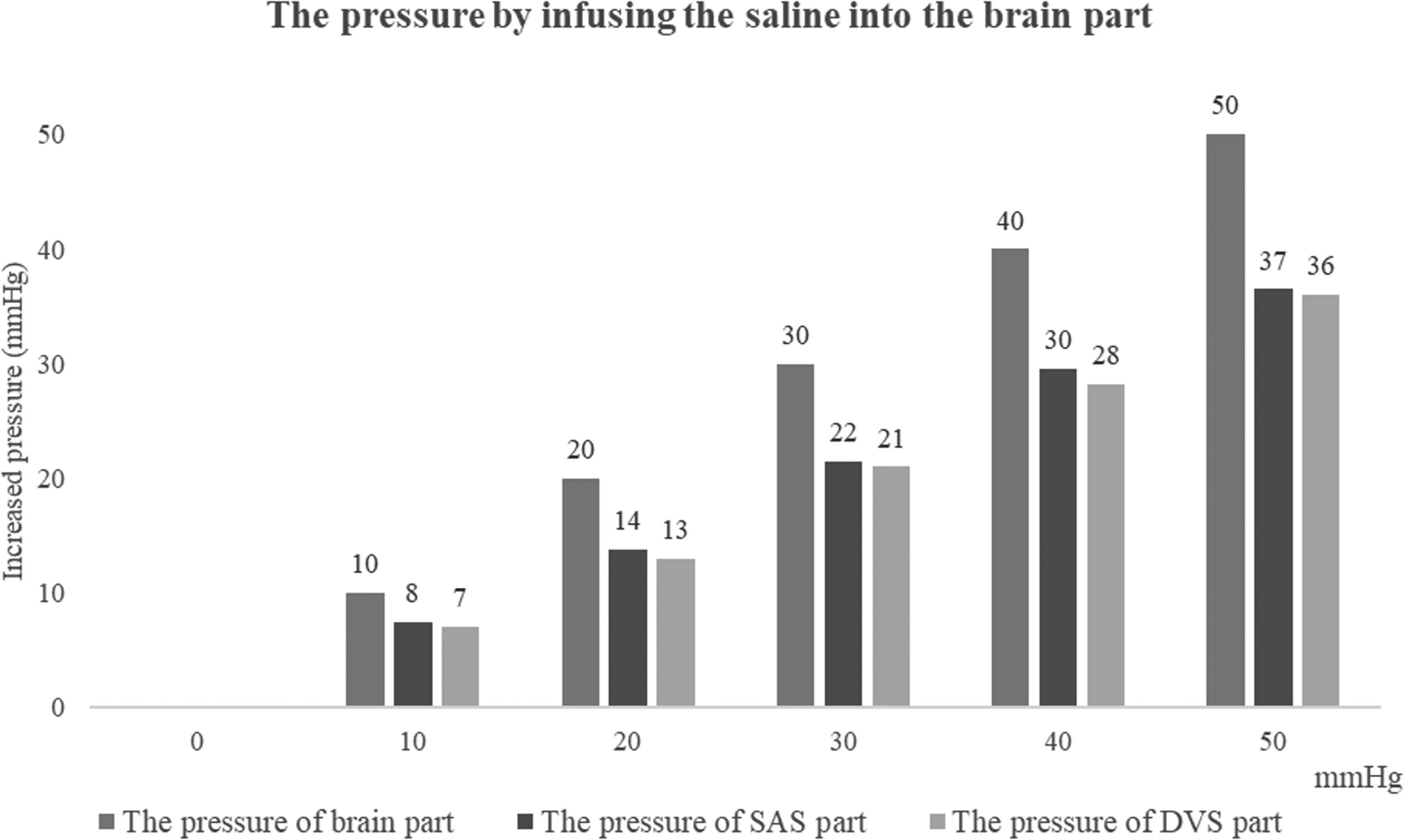
The mean values of the increased pressures in the SAS part and the DVS part by infusing the saline into the brain part.
Pressure change according to step wise pressue increase in brain part.
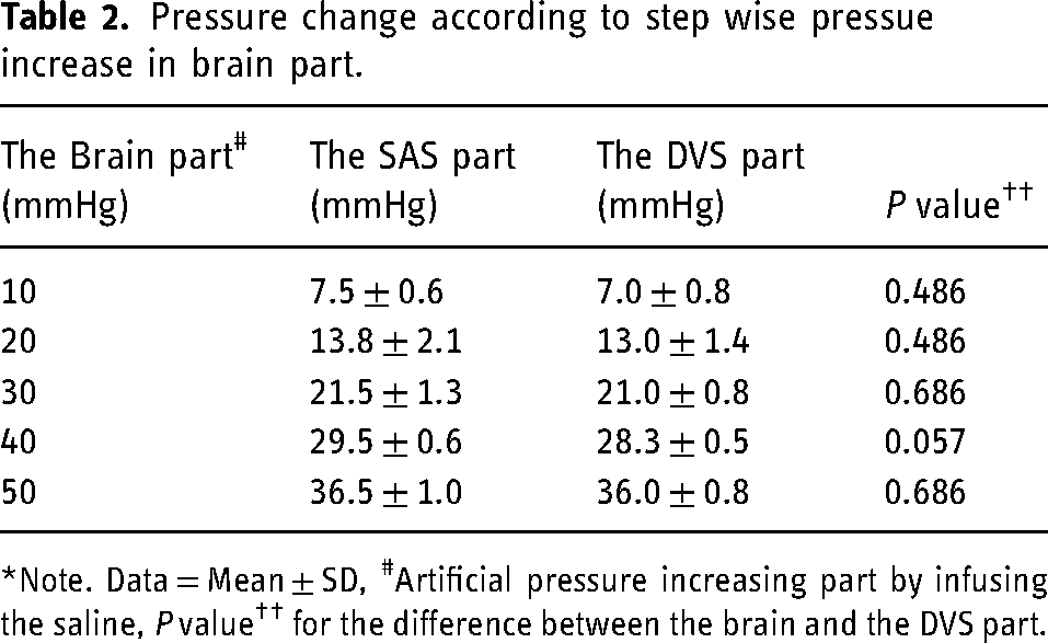
*Note. Data = Mean ± SD, #Artificial pressure increasing part by infusing the saline, P value†† for the difference between the brain and the DVS part.
Discussion
With this simplified experiment, we could partly prove the feasibility of using the DVS as a window in measuring the ICP especially when the ICP was increased due to the increased pressure of the SAS since we could note a good correlation between the pressures of the SAS part and DVS part.
Contrary to our expectation, we failed to show a similar pattern of pressure between the brain part and DVS part. While we increased the pressure in the brain part gradually the pressures in the SAS part and DVS part were also increased but just up to 70% of the increased pressure, while the pressures of the SAS part and DVS part were similar (Figure 5). The measurement results are implied that the pressures in both SAS and DVS parts could not reflect the increased pressure of the brain part due to the presence of a pressure barrier between them. However, it was considered to be due to our faulty application of the known brain compliance (0.7∼0.8) in the fabrication of the brain part using silicone material.11,12 The brain compliance should have to be interpreted as intracranial compliance, not as the literal ‘brain’ compliance, which would be lower than the ‘intracranial’ compliance. If we had the brain part having a lower compliance value then we might have seen a good correlation. Since we currently lack data on exact brain compliance further study on this issue would be helpful for a better understanding of intracranial compartmental pressure and volume interactions.
We cannot overemphasize the importance of continuous or repeat measurement of the ICP not only in the management of various neurocritical situations but also in some particular benign conditions such as idiopathic intracranial hypertension or idiopathic normal pressure hydrocephalus. Intraventricular-type or bolt-type devices are current options for most of the neurocritical conditions, however, use of those devices could be limited in patients with bleeding diathesis, such as hepatic encephalopathy due to acute fulminant hepatic failure. 13 In those conditions, monitoring the DVS pressure, which may reflect the ICP by transvenous approach could be a less invasive alternative. The venous access could be done via antecubital vein as we commonly perform for the placement of the peripherally inserted central venous catheters. Placement of a microcatheter or a pressure-sensor wire in the DVS, hopefully, the superior sagittal sinus or transverse sinus, would not be a difficult procedure for the neurovascular interventionists since DVS procedures are getting popular these days.14,15 Although Bottan et al. developed a complex phantom model of ICP, 16 exact modeling and creation of a physiologic model would be challenging. We found fabrication of a simple model was also not that simple. Other than our mistake related to the compliance of the brain part, the creation of the DVS part running along the inner convexity of the skull part was also difficult since the creation of sinus-like channel having the consistency and mechanical property of the fibrous dural structure in simple tube structure seemed not possible. To cope with this problem, we did not adopt the usual silicone vascular tube as we usually applied for the intracranial artery phantom creation. We decided to create a silicone tube with a thinner but studier wall. The wall thickness and the diameter of the DVS part were reproduced by taking the actual sinus profile into account.17,18 Keeping an appropriate flow in the DVS part connected to the closed-circuit using a peristaltic pump was also an important point to consider since the simplified DVS part model was different from the actual DVS which has upstream cortical veins even though the connection is believed to be less significant due to the Starling resistor phenomenon in case of increased ICP. 19 Since simple modeling was not feasible for the dural sinus venous pressure changes secondary to the increased ICP, we chose the circuit flow as low as possible to prevent any inflow pressure effect in this simplified model. Since the thin-walled silicone tube of the DVS part was easily compressed by the increased pressure of the SAS part as we commonly observe on the venography of the patients with idiopathic intracranial hypertension, 20 pressure accumulation would be a problem at the inlet segment of the tube, and choice of the lowest flow was technically inevitable. Regarding the close relationship between the ICP and the DVS pressure, there remain lots of unanswered questions, such as 1) where is the most reliable and representative anatomic location of the DVS pressure, 2) what if there are significant anatomic variations of the DVSs, 3) influence of the intracranial compartmental pressure difference to the DVS pressure, or 4) influence of either intrinsic or extrinsic stenosis of the DVS itself. Furthermore, various metabolic and hemodynamic effects, such as the cerebral perfusion pressure, peripheral arterial CO2 tension, type of anesthesia, particular drug effect, etc., should also be considered to understand better the instantaneous relationship between the DVS pressure and ICP.21,22
Some of the limitations of this simplified model were already discussed, however, during the actual measurement by applying gradual pressure increment, we experienced problems due to the leaks via the holes of the skull part for the insertion of the DVS tubes. We may get rid of this problem by fabricating the model as a single unit while the brain part has a similar physical modulus to the actual brain parenchyma. In this study, the potential influence of venous hemodynamics in the compressed DVS was not evaluated especially under the conditions of increased ICP, and careful interpretation of the DVS pressure measurement result is needed under the real-world clinical setting even though coupling of sinus pressure and ICP has already been documented clinically. However, potential venous hemodynamic contamination could be a problem in adopting DVS pressure as the surrogate of the ICP in particular clinical conditions, such as combined intrinsic steno-occlusion of the DVS or dural arteriovenous fistula. Lastly, our employed model has symmetrical transverse sinuses, which occur in only 35–60% of the normal population. However, approximately 50% of people have a dominant transverse sinus instead of symmetrical sinuses. 23 Therefore, experiments using models with dominant transverse sinus should be added in the future since the flow dynamics and pressure gradients might be different in the hypoplastic venous sinuses.
Despite these limitations, we believe this simplified model can be useful in the understanding of basic mechanical interaction between the intracranial compartments if properly modified. The next experiment we would like to perform with this model is to see the influence of intrinsic stenosis of the DVS in the sinus pressure.
Conclusions
Although there are several points to be improved, the simplified, in-house cranial cavity model consisting of three compartments seems to be useful in a basic understanding of the mechanical pressure relationship of intracranial compartments. The pressure measured in the dural venous sinus could be a surrogate of intracranial pressure.
Supplemental Material
sj-docx-1-ine-10.1177_15910199221107440 - Supplemental material for A simplified cranial cavity model to understand the relationship between intracranial pressure and dural sinus pressure
Supplemental material, sj-docx-1-ine-10.1177_15910199221107440 for A simplified cranial cavity model to understand the relationship between intracranial pressure and dural sinus pressure by KB Lee, MH Kim, J-T Yoon, Y Song, B Kwon, SM Hwang, JH Choi and DH Lee in Interventional Neuroradiology
Footnotes
Acknowledgements
We expressed our gratitude to Byung-Jun Lee, who helped with technical assistance in acknowledgements.
Declarations of interest
The authors declared no potential conflicts of interest regarding the research and publication of this article.
Ethical approval statement/IRB approval number
IRB approval was waived for this study, due to the in-vitro experimental design.
Funding
D.H.L; This work was supported by the Advanced Technology Center Plus (ATC + ) Program (Grant numbers: 20009512) funded by the Ministry of Trade, Industry & Energy (MOTIE, Korea).
The funders had no role in study design, data collection and analysis, decision to publish, or preparation of the manuscript.
Supplemental material
Supplemental material for this article is available online.
References
Supplementary Material
Please find the following supplemental material available below.
For Open Access articles published under a Creative Commons License, all supplemental material carries the same license as the article it is associated with.
For non-Open Access articles published, all supplemental material carries a non-exclusive license, and permission requests for re-use of supplemental material or any part of supplemental material shall be sent directly to the copyright owner as specified in the copyright notice associated with the article.