
Abstract
Recent developments in steel alloys metallurgy followed the automotive industry need for enhanced crash safety, fuel economy and customer satisfaction. In this work, a group of innovative steel alloys, belonging to different Advanced High Strength Steels generations, sourced from available studies, were subject to a comparative study to test their toughness in a reference fracture mechanics scenario. A commercial FEM code was used, employing two widespread approaches to fracture mechanics. The results allowed to make considerations about the use of some popular steel alloys in the automotive industry, highlighting the importance of FEM in the mechanical engineering sector.
Keywords
Background
In the automotive field, there is a growing interest in balancing the goals of fuel economy standards, crash safety and consumers demands. 1 For example, according to the standards provided by the Corporate Average Fuel Economy (CAFE), the automotive industry original equipment manufacturers must meet the fuel economy target in the average weight of the fleet. 2 In parallel, the market is pushing towards the development of greener, stronger, lighter and less impacting auto vehicles. 3
One of the approaches to reach these goals consists of the use of lightweight materials in automotive field with a view to reducing the weight.4,5 In fact, Hirsch 6 highlights that 100 kg of vehicle weight reduction results in 9 g of carbon dioxide reduction per kilometer. However, even if an obstacle in using lightweight materials in automotive industry can be represented by their high cost, the present trend is to substitute conventional steel with Advanced High Strength Steel (AHSS). 7 Furthermore, by combining 1st, 2nd and 3rd generation steels, such as transformation-induced plasticity (TRIP), twinning-induced plasticity (TWIP), and nano-precipitation strengthening steel8–9; Fe-Mn, and Al alloys guarantee high strength, high toughness, low density, impact resistance, with tensile strength of 700–1100 MPa, and its density can be reduced to 6.5–7.0 g/cm3, a reduction of about 11–18%. 10
Advanced high strength steel adopted for automotive exhibit a good combination of formability and high strength; the former is higher if compared to the conventional micro alloyed steels of similar strength, 11 and this is due to a higher strain hardening capacity. 7
Conventional advanced high strength steels are generally not lighter than low-carbon but exhibit a higher strength, and this aspect allows to achieve an overall weight reduction for the vehicle. 3 More in detail, if mild steel is substituted by advanced high-strength steel, it results in a remarkable decrease in the sheet depth of the front-body parts of the vehicle, by keeping identical or greater energy capacity in case of impact. 12
Generally, as it is shown in the tensile strength-elongation diagram reported in Fig. 1, different steel grades result in a difficulty in reaching both high strength and ductility: for example, low carbon steels have good formability but relatively low tensile strength (generally lower than 270 MPa), while conventional High Strength steels (HSS), generally comprised in the region between Interstitial Free (IF) and High Strength Low Alloy (HSLA) steels, can reach a tensile strength between 270 MPa and 700 MPa, but lower elongation. 3
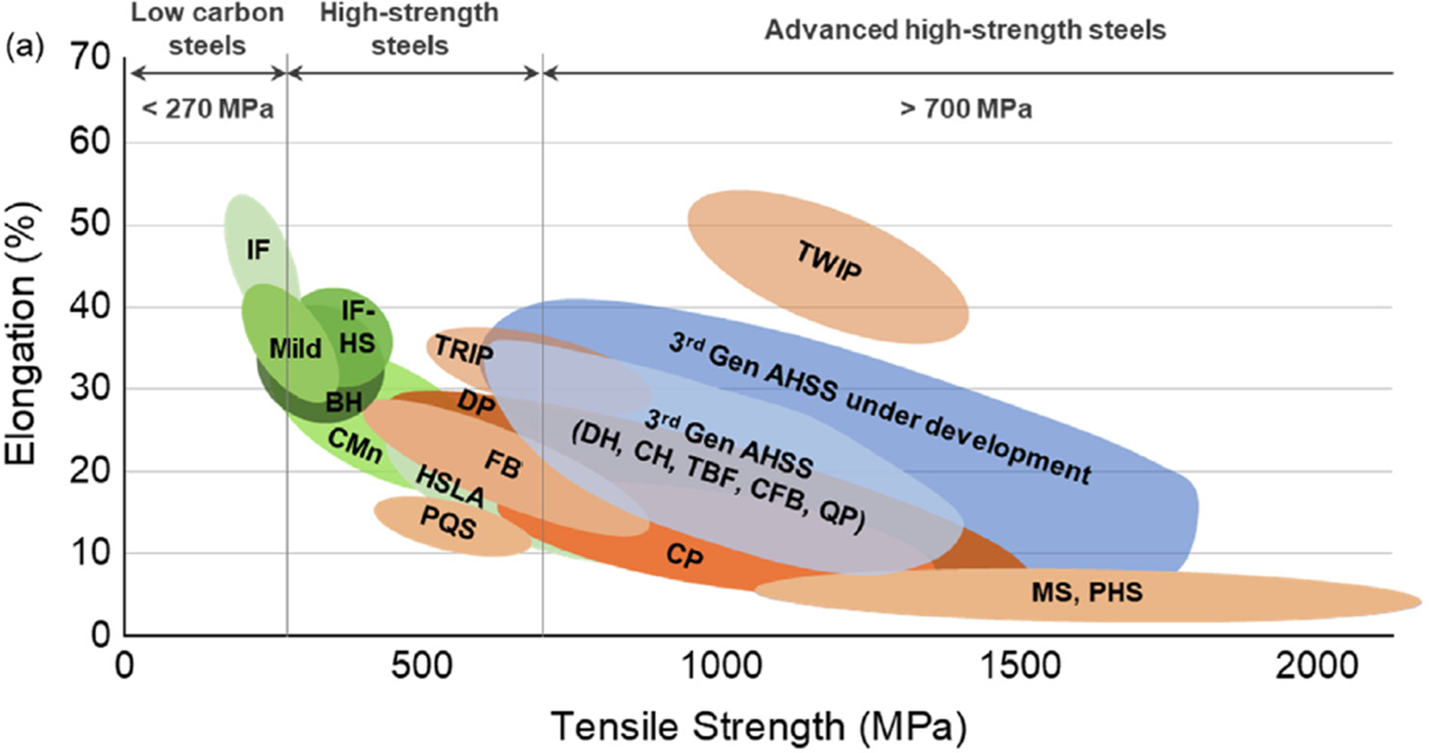
First generation AHSS are designed with the objective of enhancing tensile strength while preserving weldability, either through adding one or more phases to the ferritic matrix (DP, CP), at the expense of elongation, or by relying on the TRansformation Induced Plasticity (TRIP) effect. The continuous transformation of residual austenitic phase into martensite islands during deformation confers the steel high hardening capabilities.11,12,3 The second generation of AHSS was marked by an effort to preserve elongation at fracture while still offering good mechanical properties. Among those, TWinning Induced Plasticity rely on twinning and de-twinning mechanisms to achieve even higher hardening capacity. The Lightweight-Induced Plasticity (L-IP) steels can be viewed as lower-density TWIP, featuring high content of Al (6–10%). 2
The most recent developments regarding AHSS are grouped in the third generation. 3rd gen AHSS are generally based on previous developments (such as TRIP/TWIP and bake hardening effects, dual or complex phases), while relying less on expensive alloy composition, and more on the precise control of heat treatments. An example is offered by Quenching and Partitioning (Q&P) steels: they are subject to a treatment, at quenching temperature, to allow the partitioning of C from martensite to residual austenite, stabilizing it at working temperature. The final structure combines the effects from the complex phase and TRIP/TWIP. 13 TRIP-assisted Bainitic Ferrite (TBF) steels achieve, through heat treatments, a bainitic ferrite microstructure, eliminating low-ductility cementite entirely, along with submicron austenitic laths form for TRIP effect. The result is a good balance between tensile strength and ductility. 13
Objective
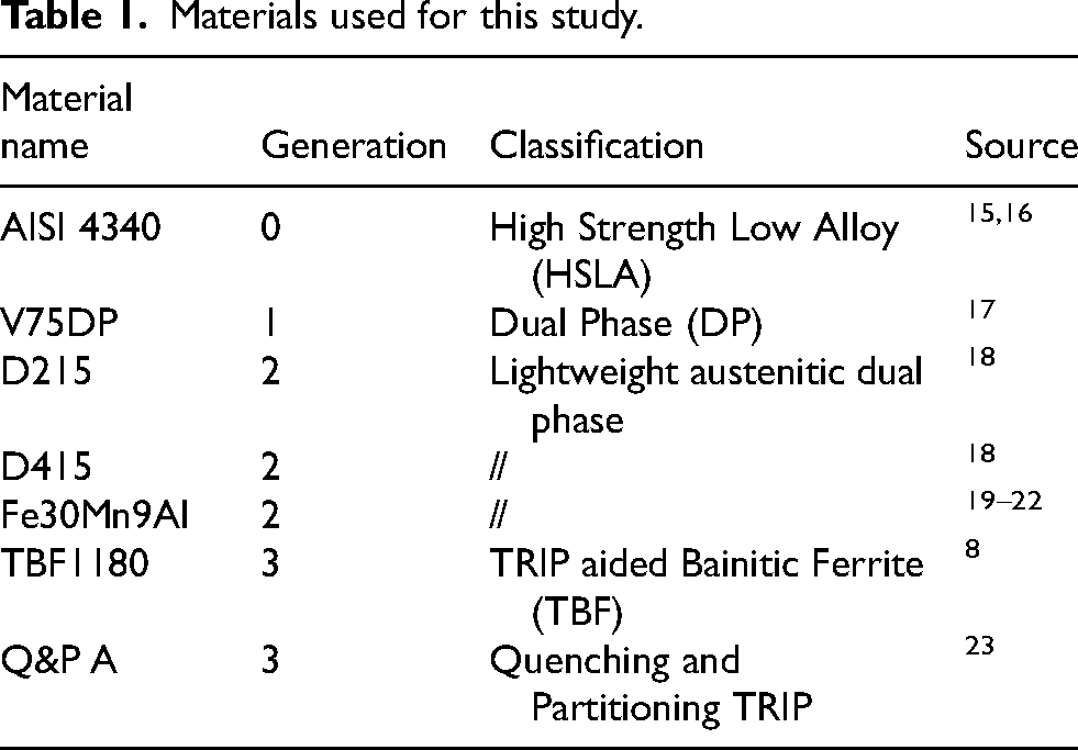
In this work, various innovative AHSS steels were considered, each featuring different chemical composition, manufacturing technique and heat treatment for the test specimens (Tables 1, 2, 3, 4, 5, 6).
Materials used for this study.
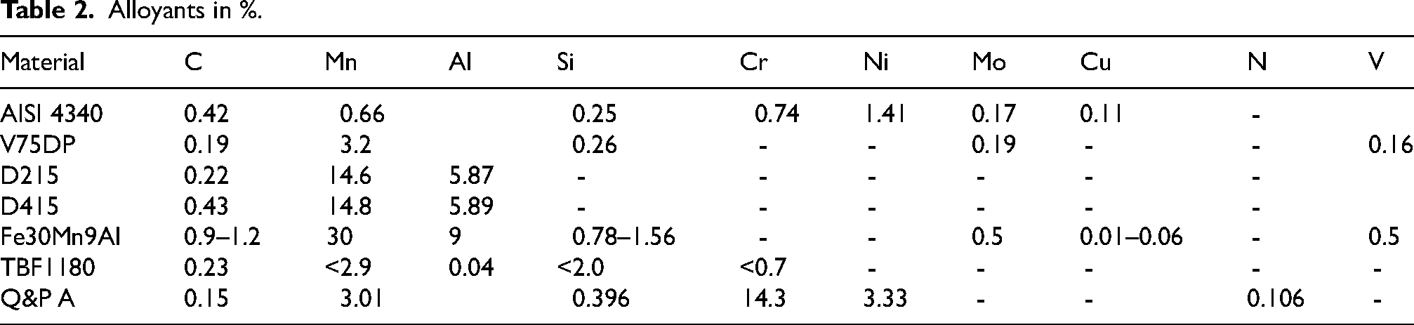
Alloyants in %.
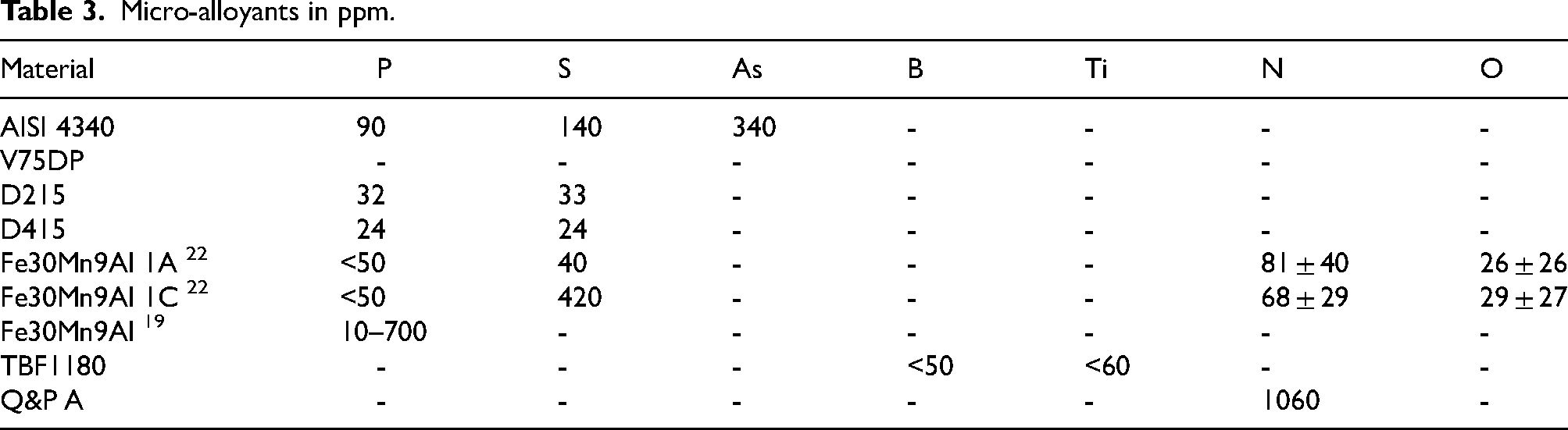
Micro-alloyants in ppm.
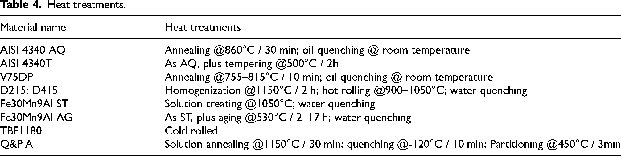
Heat treatments.
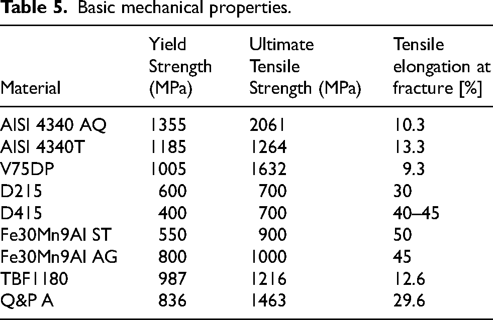
Basic mechanical properties.
Fracture toughness properties.
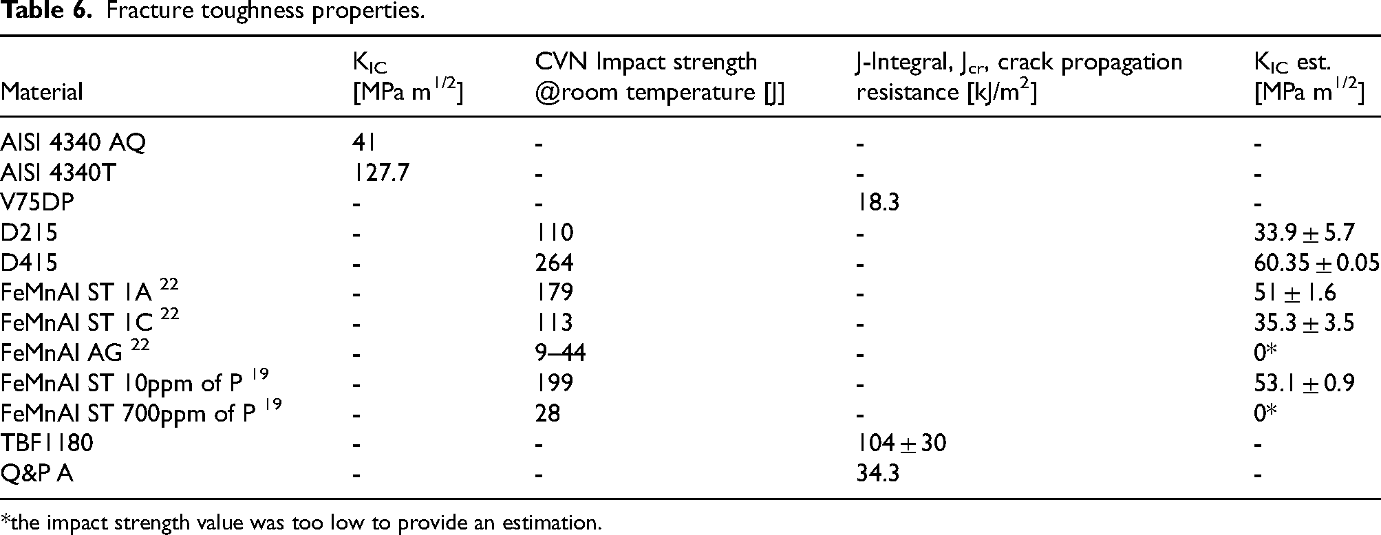
*the impact strength value was too low to provide an estimation.
Figure 2 summarizes the materials included in this work, following the notation used by the respective reference papers for the nomenclature:
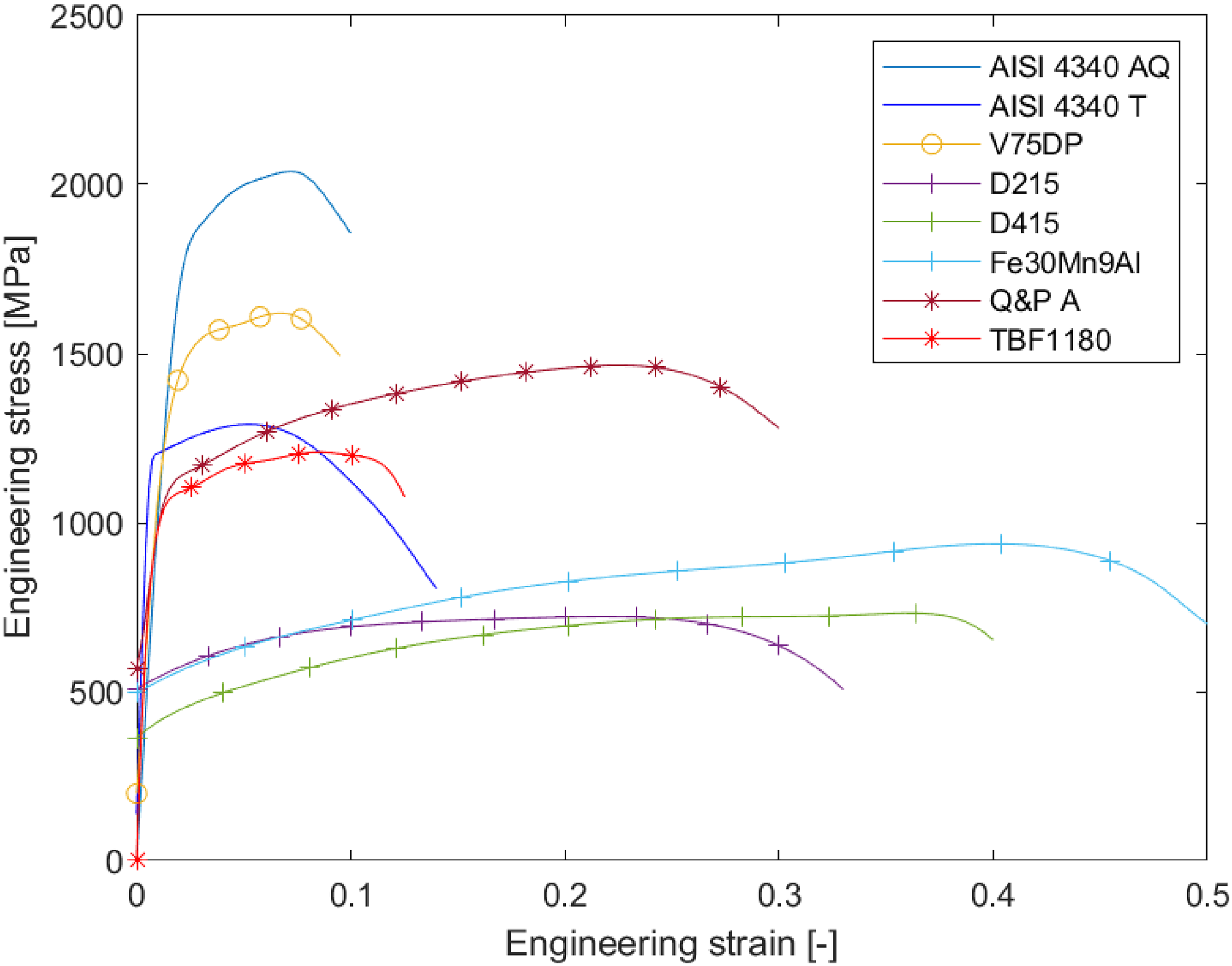
Stress-strain curves.
The AISI 4340 steel is considered as a conventional High Strength Steel, to be compared with AHSS's, hence the marking as “Gen 0” in Table 1. A particular focus was on lightweight, dual phase steels, such as Fe15Mn6Al and Fe30Mn9Al. It was found that their fracture toughness is, predictably, largely dependent on heat treatments, chemical alloyants and micro alloyants. Yang et al. 18 found that in two Fe15Mn6Al steels, featuring different amount of C, and subject to the same heat treatments and specimen preparation procedure, the D415 featured lower yield strength, higher tensile elongation at fracture and much higher fracture toughness. It is noted how these materials performed noticeably worse in the Charpy V-Notch (CVN) impact resistance test than in the tensile elongation department, due to the significantly higher strain rates in the CVN. For the Fe30Mn9Al steels, Bartlett et al. 2014 19 highlighted how high concentration of phosphorous inclusions severely decreases the CVN fracture toughness; Vaz Penna et al. 22 instead examined specimens with different sulfur and other non-metallic inclusion concentrations, and found that, coupled with the aging treatment, they also dramatically lower the specimen fracture toughness.
Methods
The various reference works employed different methods to estimate the specimens fracture toughness. This is also reflected in the present manuscript. For the materials which were provided with the CVN impact strength values, the relation from,
24
reported as Equation 1, allowed to estimate the fracture toughness value in high strength steels.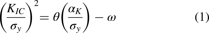
The supplied data were adopted to perform a fracture toughness estimation using the commercial FEM software Marc Mentat 25 in order to look at the problem from the viewpoint of the technical personnel belonging to average design companies. General concepts pertaining to FEM analyses are available in various manuals, often included in the specific software documentation. An example is the work from Cook et al. 26
A perforated plate, subject to a traction load amounting to 250 MPa, was used, in order to provide a model already featuring stress concentration without the crack application. A plane strain quasi-static analysis was chosen to take advantage of the geometrical and boundary condition symmetry to simplify the mesh. The width and length of the plate are considered both as 100 mm, while the hole measures 20 mm in diameter. The thickness is set as 1.5 mm, in accordance with the most common test specimen geometries employed in the various works. The model, without the crack, is shown in Figure 3. The mesh is made of 5648 quadrilateral plane strain linear elements and 5825 nodes. The materials follow an isotropic elastic-plastic formulation, employing the Von Mises yield criterion, according to the stress-strain laws described in Figure 2. The Young's modulus and Poisson ratio were either set as the one specified by the reference material for the particular steel or assumed to be of average value for steels (205 GPa and 0.3 respectively).
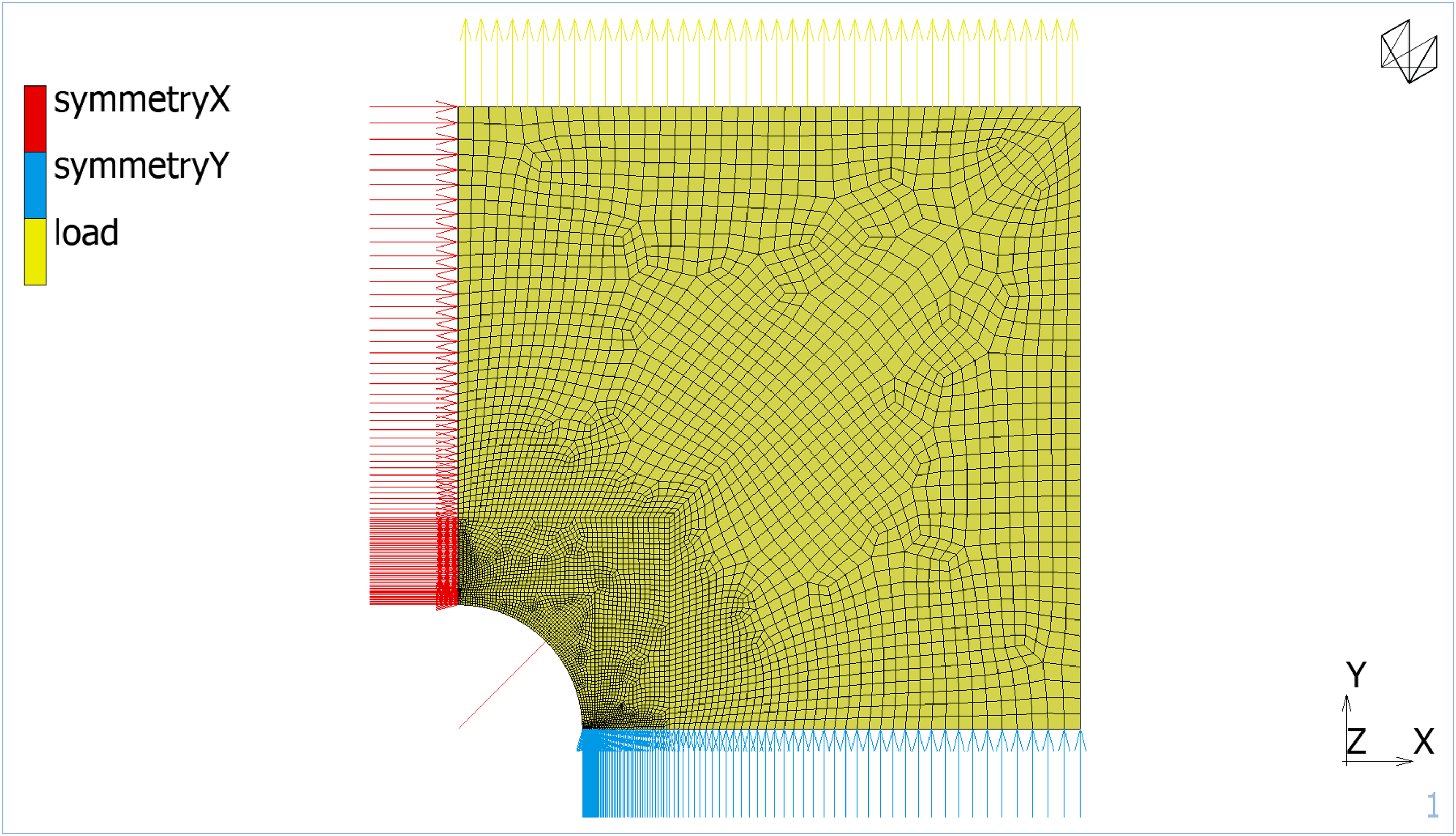
Mesh and boundary conditions for crack-less specimen.
A preliminary crack-less analysis is reported in Figures 4 and 5. The y components of stress and strain are distributed according to the expected lobe shape. The maximum stress, acting on the hole apex, is reported to be 601.7 MPa, which corresponds to a KT = 2.41. The value is consistent with the various available KT tables referring to this geometrical configuration. The εyy strain observed, peaking at 2.673·10−3, is well below the conventional limit for elastic behavior.
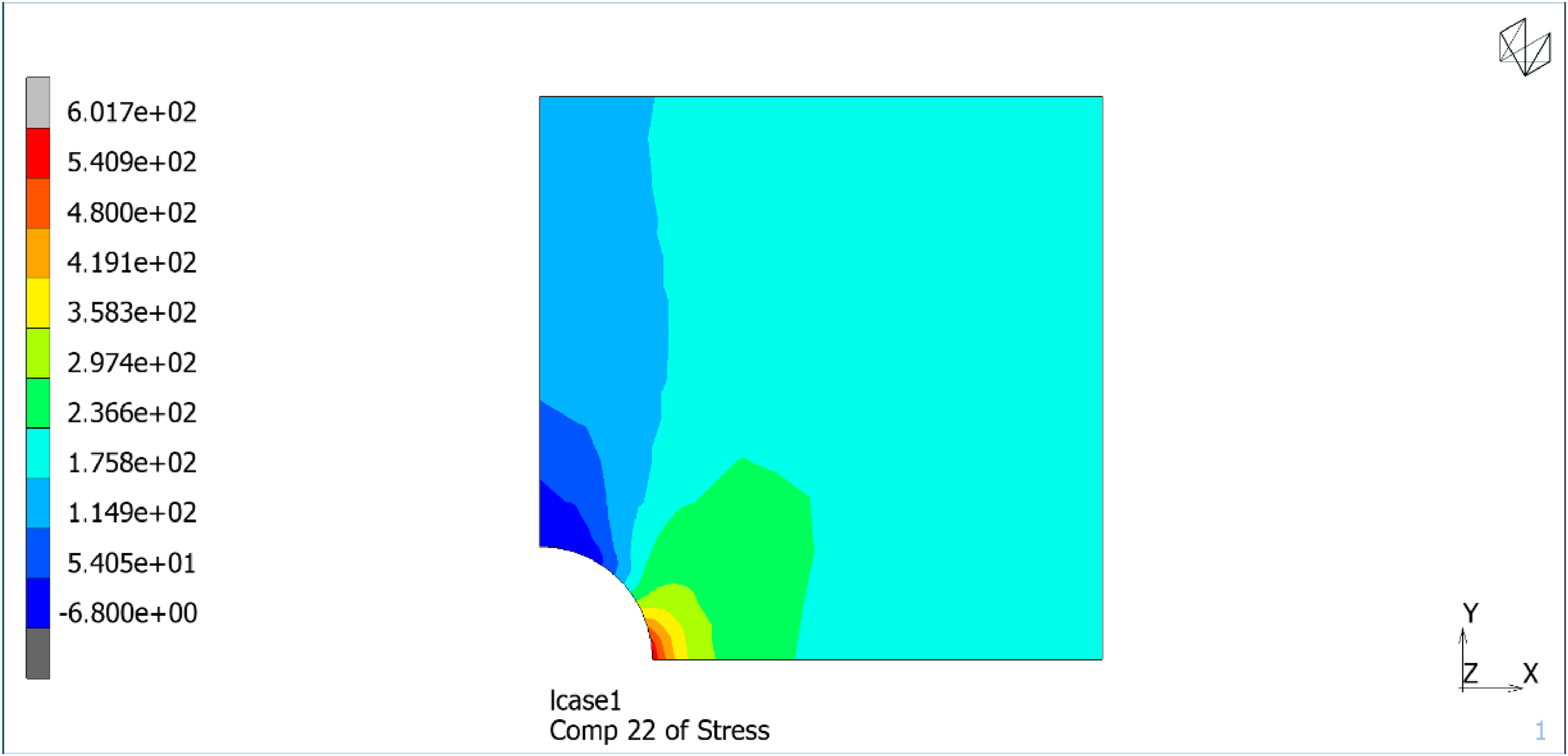
σyy stress distribution on the crack-less specimen.
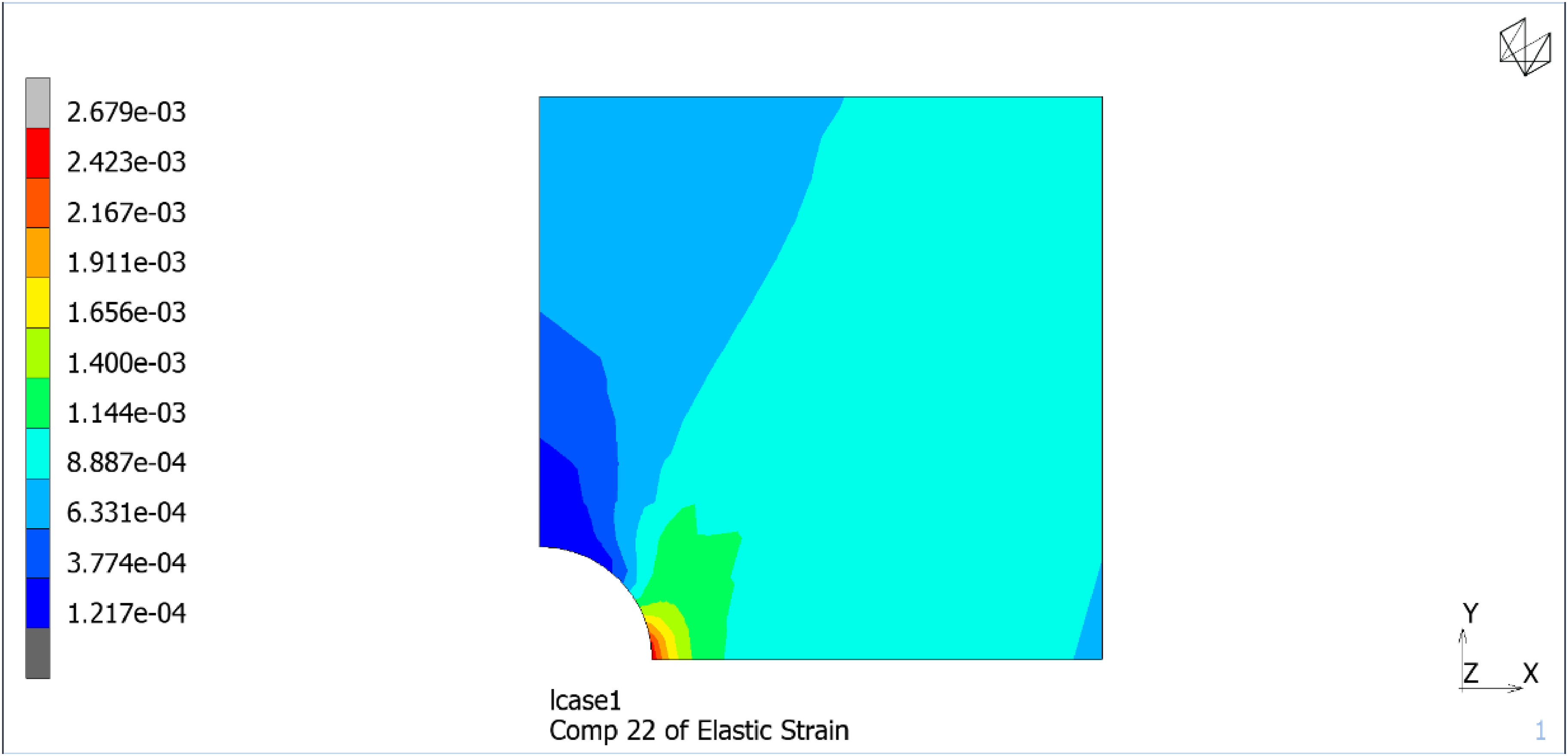
εyy elastic strain distribution crack-less specimen.
The fracture mechanics quasi-static analysis was then performed by using both the 2D J-integral and the 2D Virtual Crack Closure Technique (VCCT) procedures embedded in Marc. While the former provides a measure of the J-integral, the latter provides an estimation of the crack energy release rate G according to the formulation by Kruger. 27
The J-Integral is a numerical technique developed in 1968 by Rice, defined according to the following Equation 2 and Figure 6: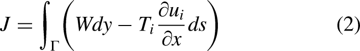
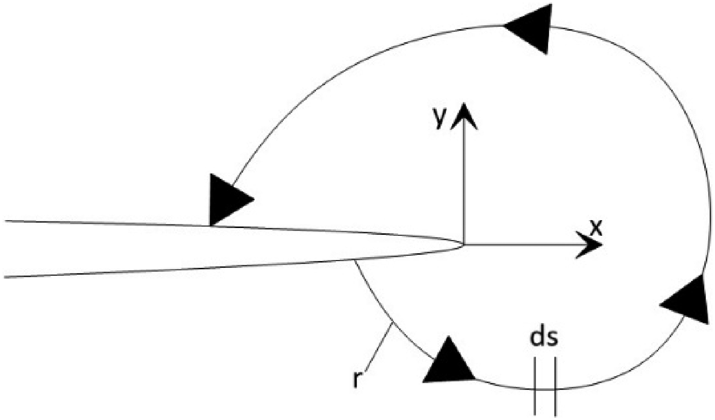
J-Integral reference geometry. 28
Considering the crack geometry as reported in Figure 7, and having defined G as the crack energy release rate, Π as the energy release, a as the defect size: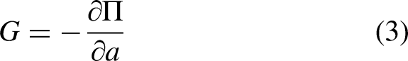
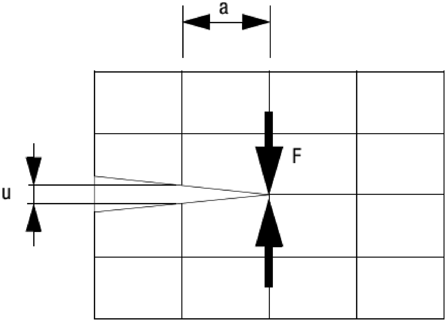
Virtual Closure Crack Technique reference geometry. 23
The total energy release rate is then computed as:
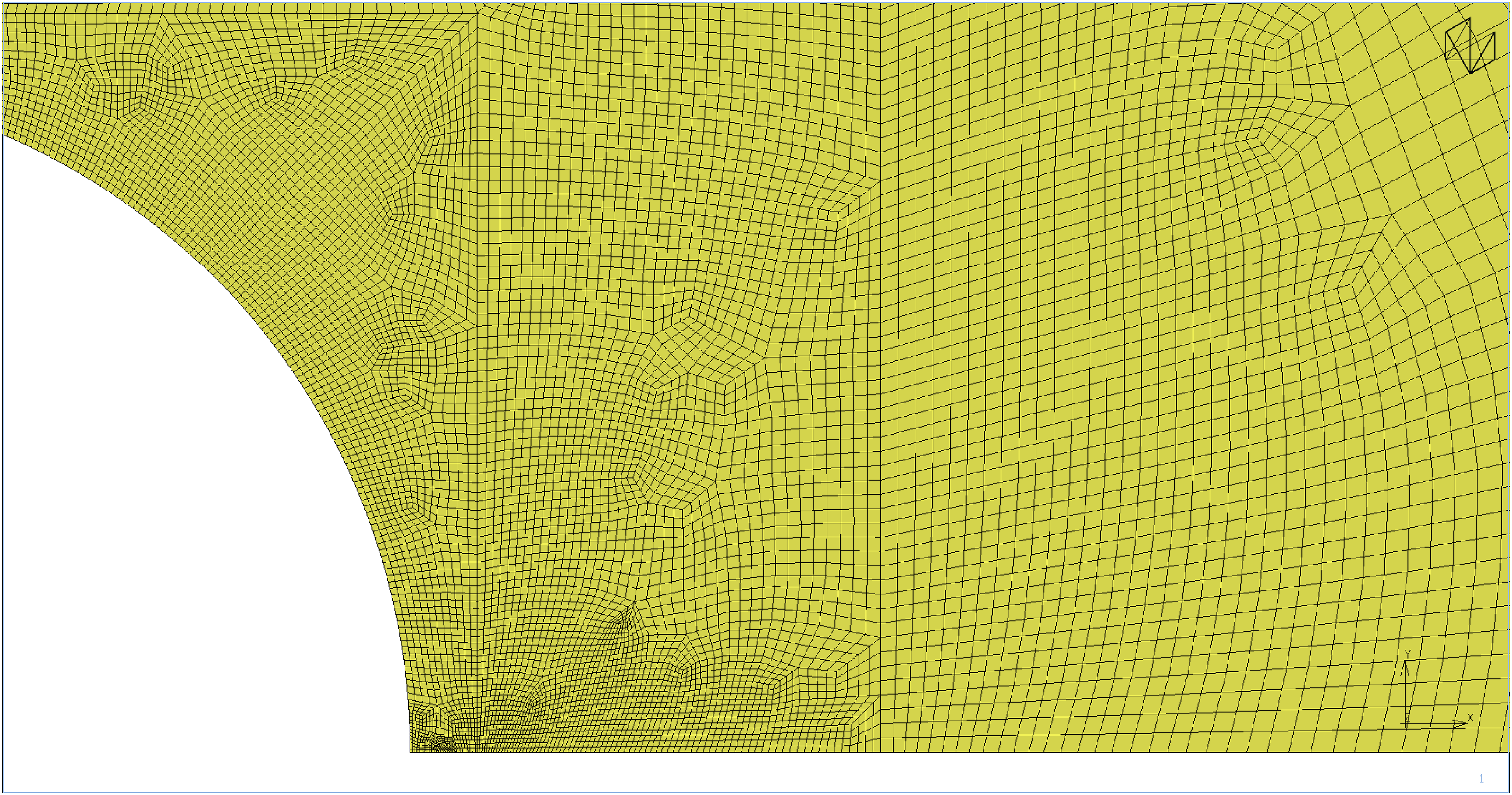
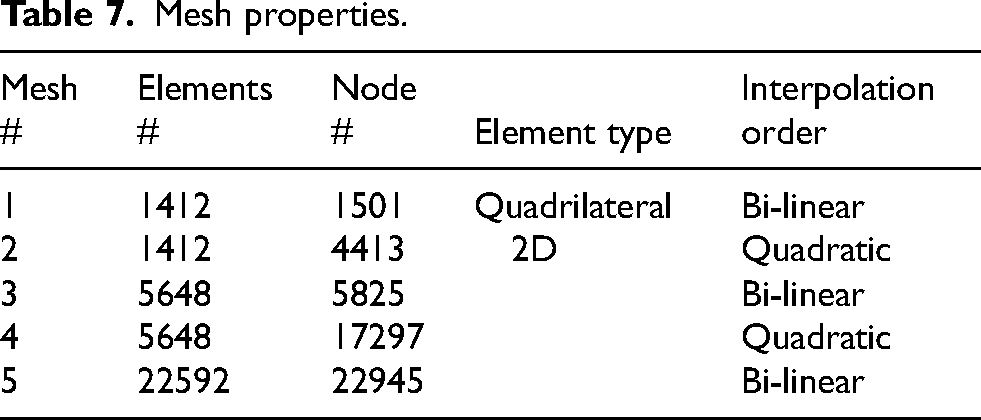
Three different crack depths of 1, 2, 4 mm, were considered, and the symmetry boundary condition was properly modified to allow the crack to open. Different meshes were modeled to provide the necessary accuracy at the crack tip. A linear elastic analysis was performed, and the results confirmed the correspondence between J and G. Once the plasticity, according to each material stress-strain curve, was enabled, the values for the two parameters started to diverge, in greater measure for the materials featuring the lowest yield strength and thus exhibiting the highest plastic strains at the crack tip. In general, the J value did not vary significatively among the pool of materials for a given crack depth, while G was more sensitive to the different plastic behaviors. The most notable outliers were found to be the D215 and D415 steels. The advantage of the J-integral crack formulation is the independence from the stress field at the crack tip, which is also known as a source of indeterminacy in the VCCT formulation. A recurring problem in FEM analysis is the inadequacy of standard 8-nodes quadratic elements for accurately describing the stress field at crack tip, with solutions such as quarter-point elements being examined. 29 A comparison of the results obtained with a linear elements mesh, a quadratic elements mesh, and finer linear and quadratic meshes was performed on the D415 steel, with a crack depth of 1 mm. The meshes and the corresponding properties are reported in Figures 8–12, and Table 7, respectively, while the results are shown in Figures 13–15 in terms of J or G and σyy:
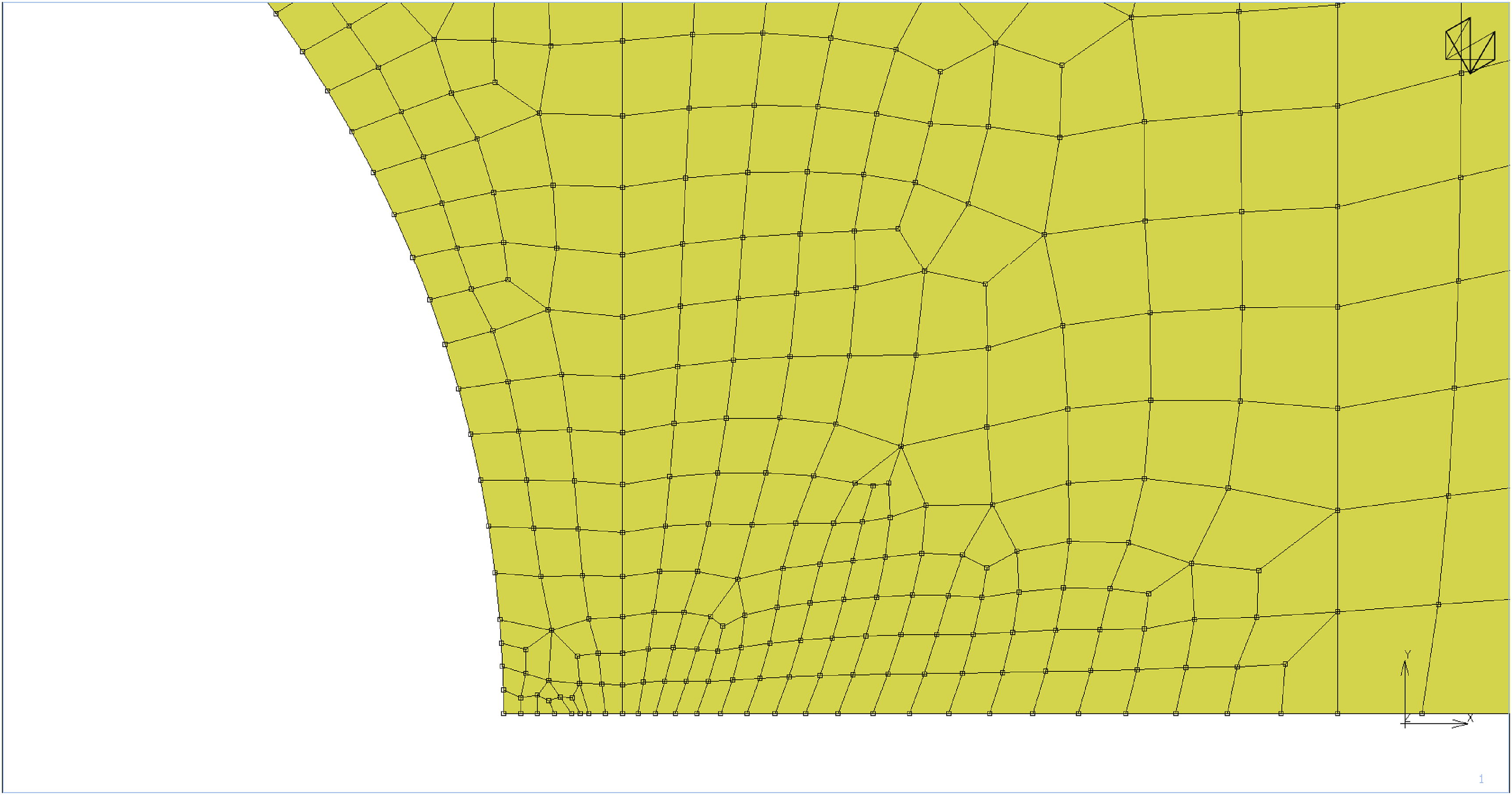
Mesh #1, linear elements, average element size at crack tip = 0.3 mm.
Mesh #2, quadratic elements.
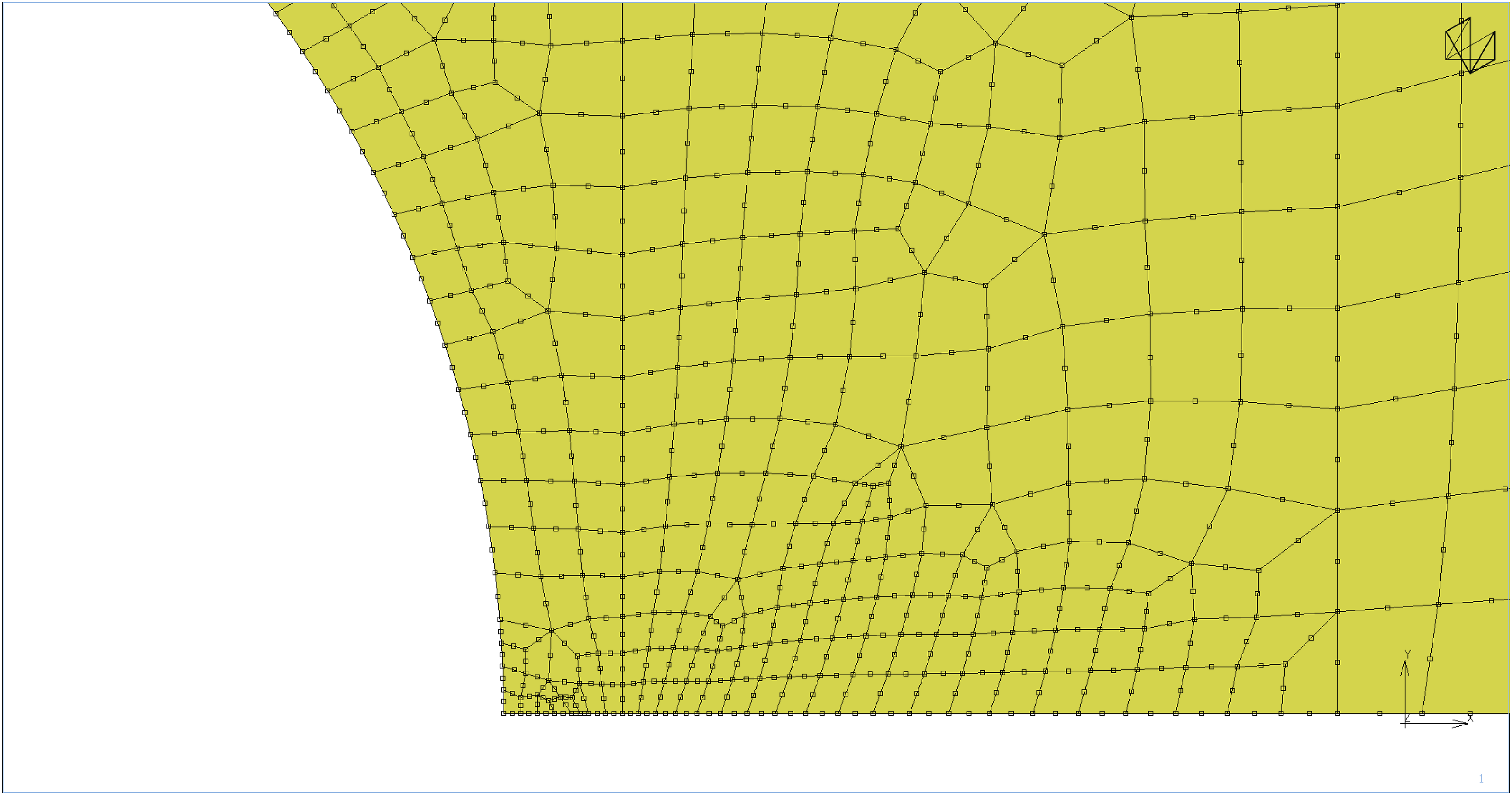
Mesh #3, linear elements, average element size at crack tip = 0.15 mm.
Mesh #4, quadratic elements.
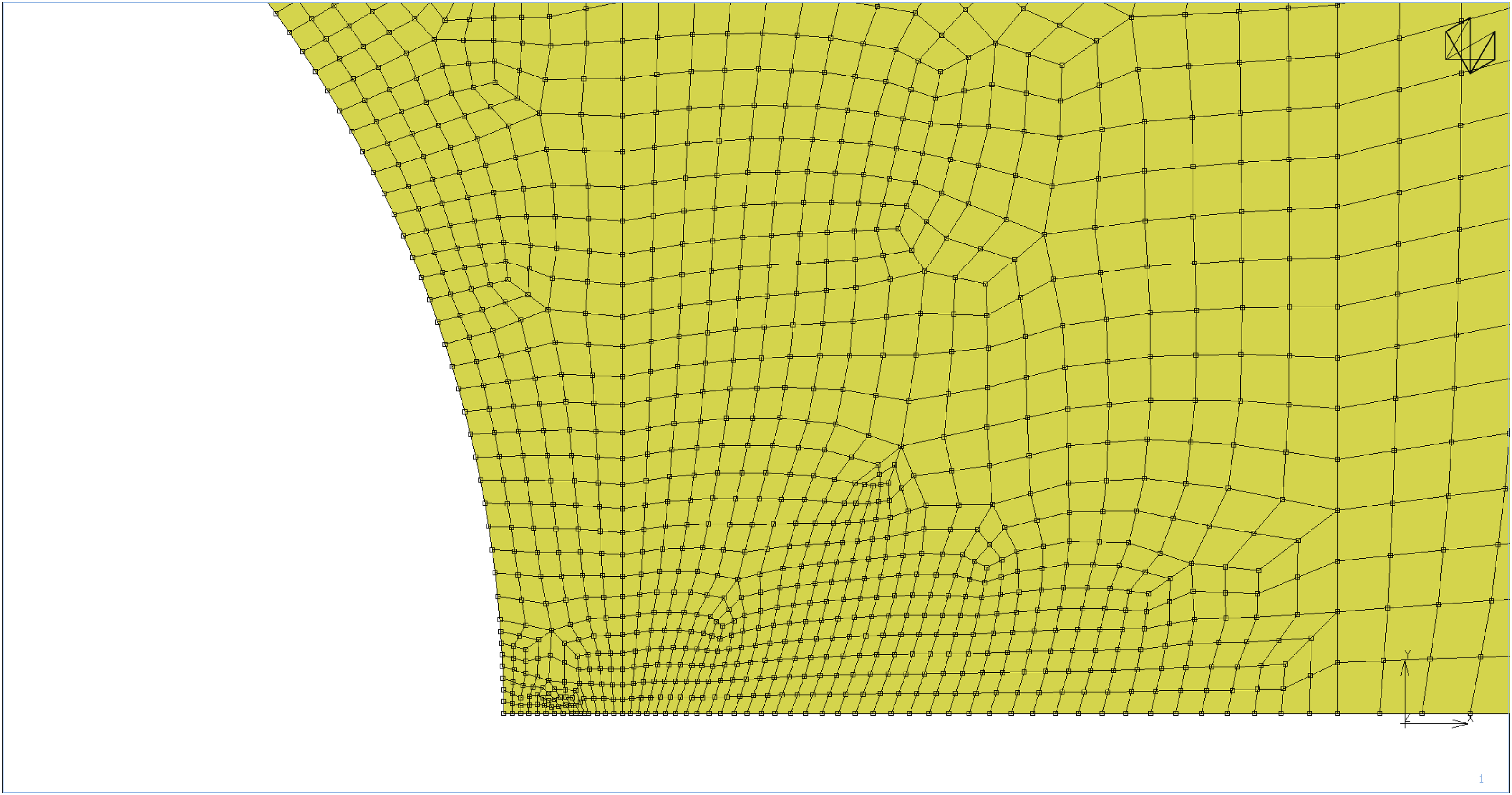
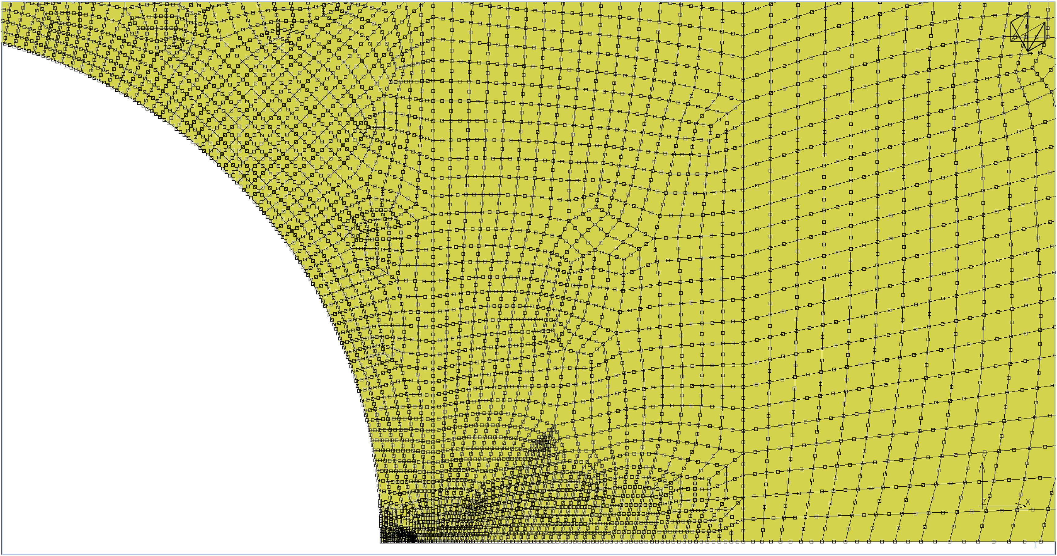
Mesh #5, linear elements, average element size at crack tip = 0.07 mm.
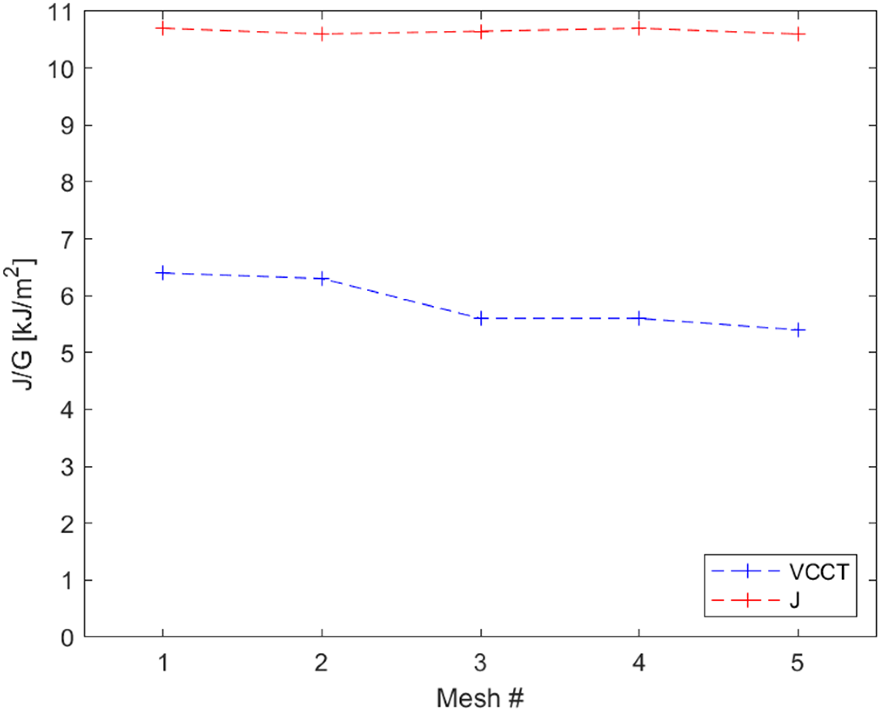
J and G comparison between meshes for material D415.
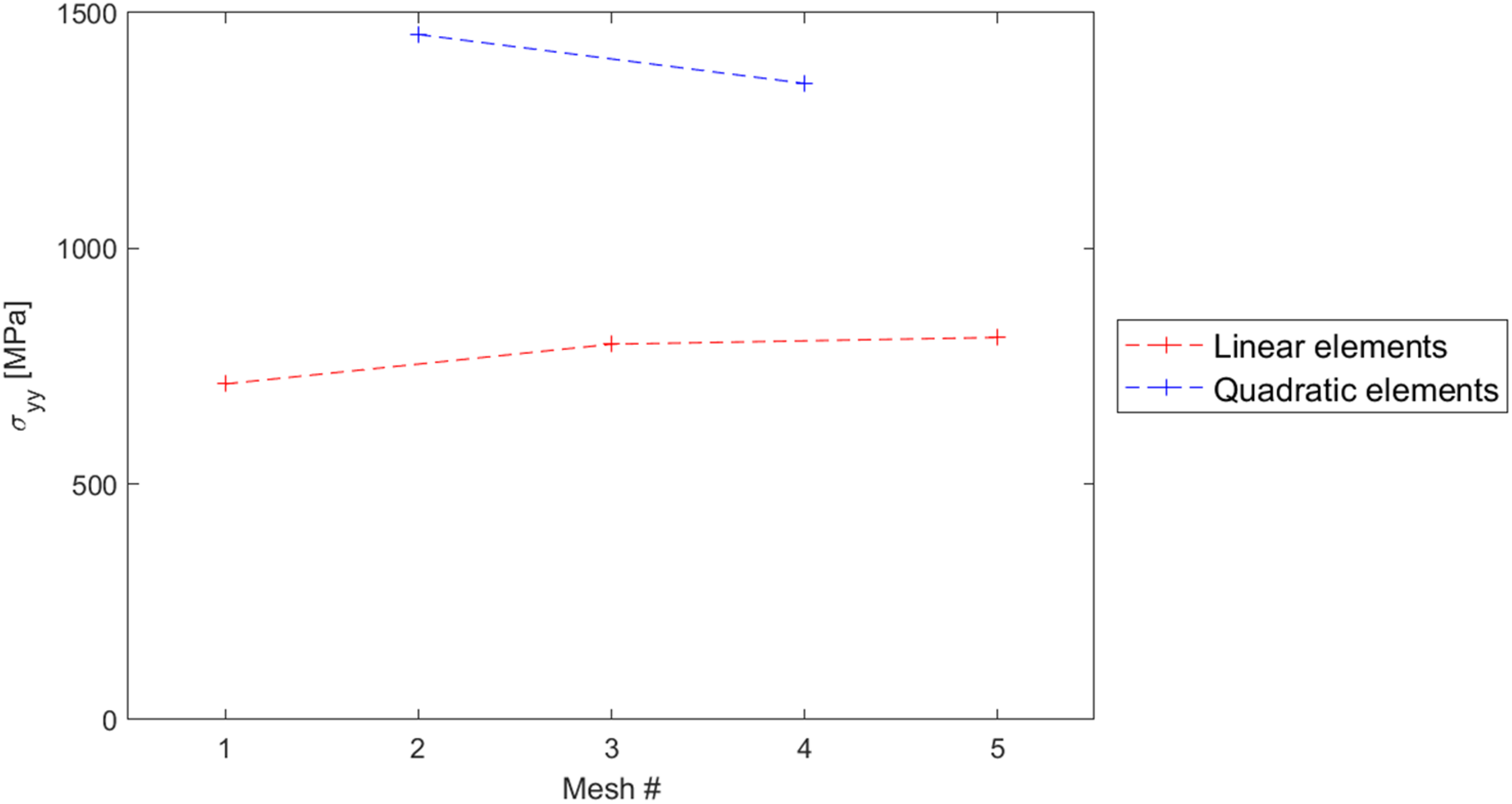
σyy comparison between meshes for material D415.
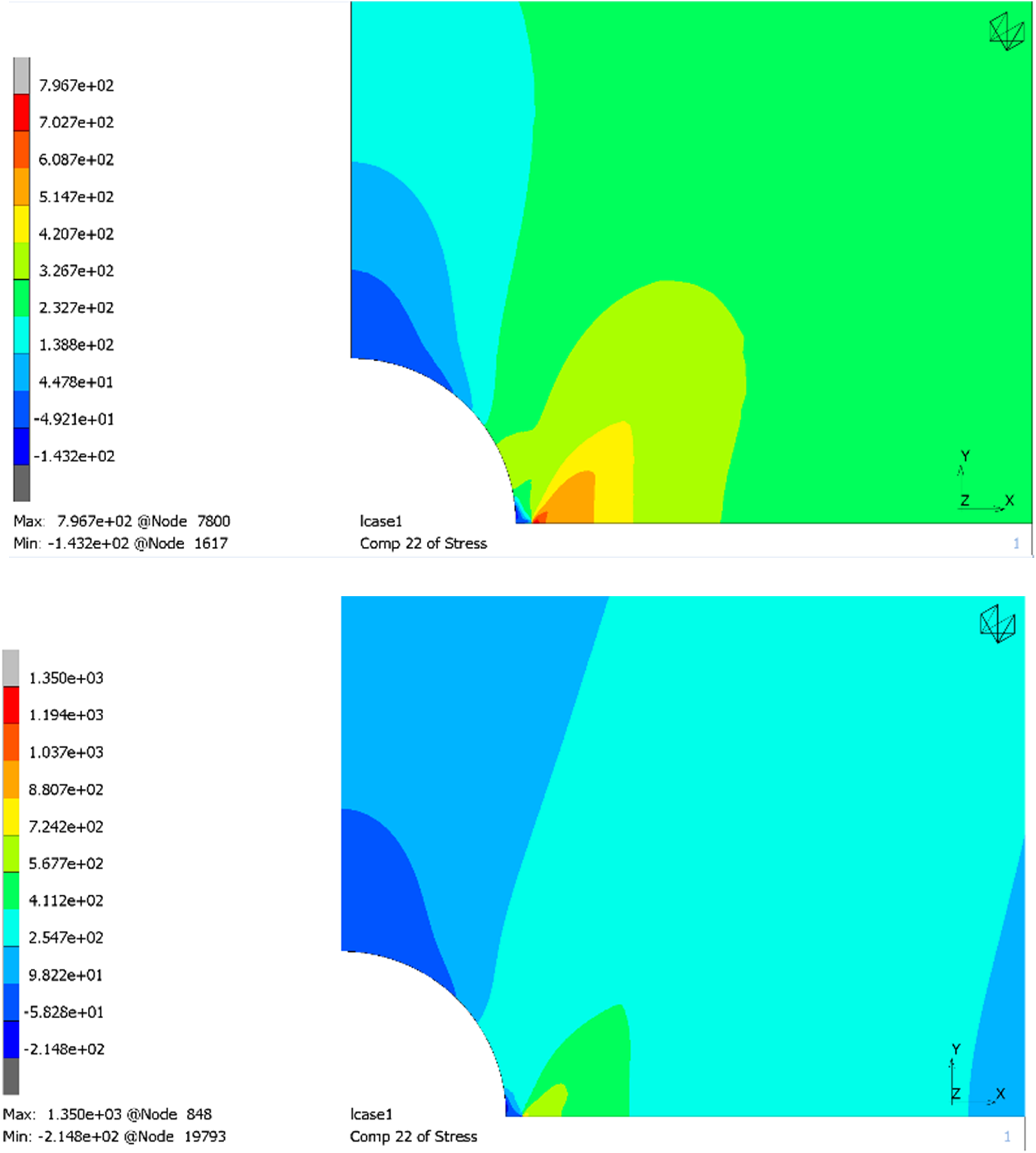
σyy distribution comparison between mesh #3 and #4 for material D415.
Mesh properties.
While the J-integral formulation was barely affected, as the results only depend on the appropriate choice of boundaries used for the integral, the G value was found to be slightly higher for the coarser mesh featuring quadratic elements.
The work from Schreurs 29 also notes that excessive element refinement in the plastic strain area leads to numerical instability. This is supported by Figures 13 and 14, which show that the meshes featuring quadratic elements exhibit much higher stress peaks, slightly decreasing with increased mesh refinement. This also supports the choice of regular linear interpolation elements.
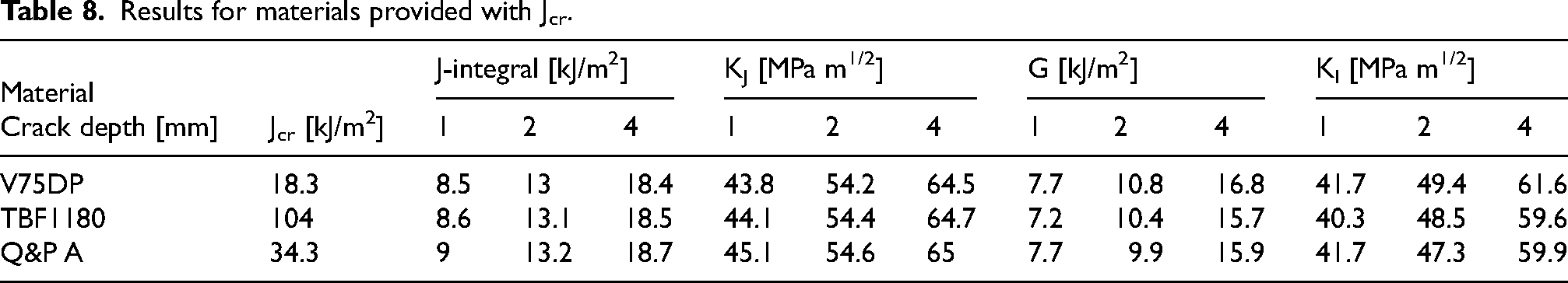
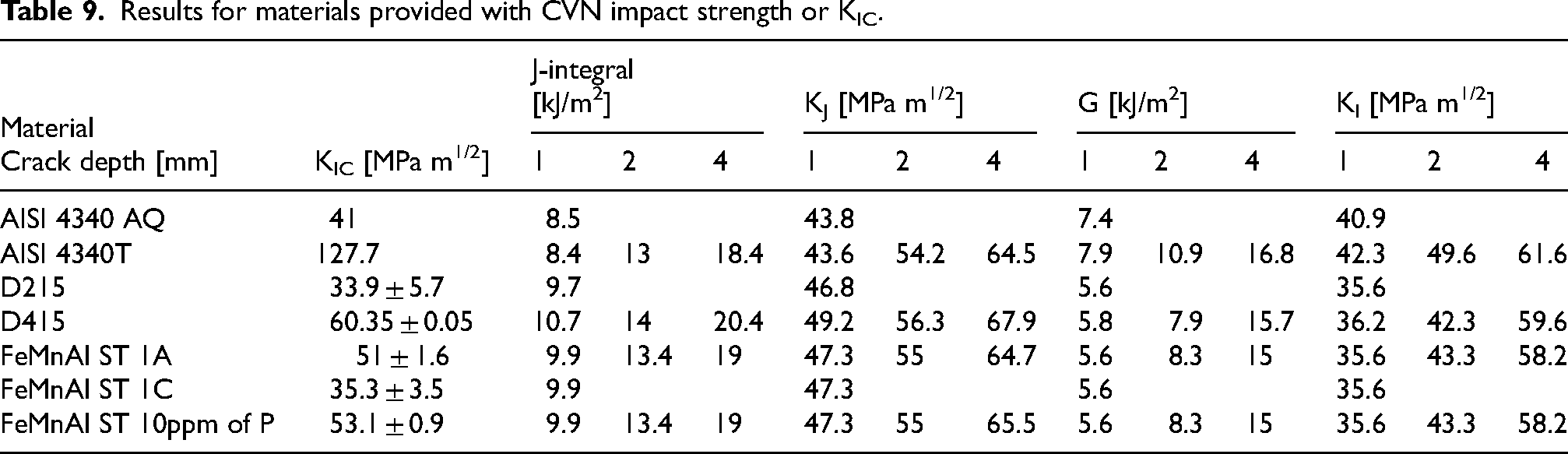
As it appears that the finer mesh is independent from the choice of elements and the Mesh #3 has reached convergence both in crack growth rate and peak normal stress, it will be used for the subsequent analyses. Two different approaches were considered for the crack resistance estimation: the V75DP, TBF1180 and Q&P A steels were provided with a critical value of J, then the J-integral value was used to estimate the fracture toughness. The rest of the materials were provided with either a KIC value (AISI 4340), or the CVN test impact toughness. In this case, the KI value estimated from G was compared to the fracture toughness. Both for the KJ and the KI, the linear elastic relationship for plane strain was used, from Equation 5. This approximation is justified by the small plastic strain zone at the crack tip.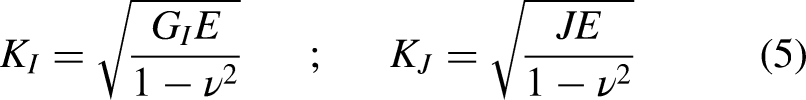
Results
The results are reported in Tables 8 and 9, and Figures 16, 17 and 18 in terms of J-integral, and KI.
J and G comparison between meshes for material D415.
Ki comparison between materials.
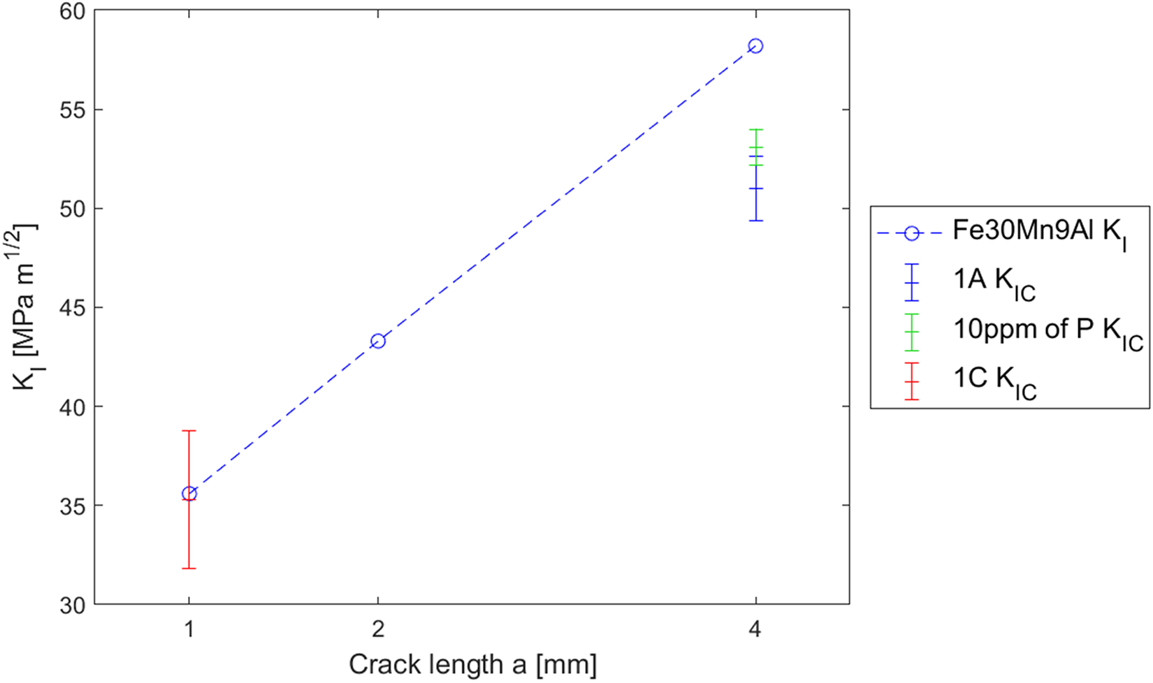
Ki comparison between Fe30Mn9Al steels.
Results for materials provided with Jcr.
Results for materials provided with CVN impact strength or KIC.
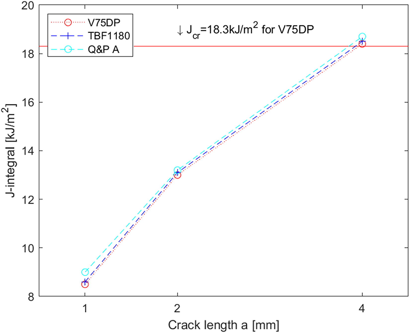
As expected, the materials behaved differently according to their respective toughness, and the simulations allowed for a comparison between them. In Figure 16, a J-integral vs crack length graph is presented. The V75DP 1st gen AHSS was found to reach the Jcr failure value, represented by the red horizontal line, at a = 4 mm, while the TBF1180 and Q&P A 3rd gen AHSS were still functional.
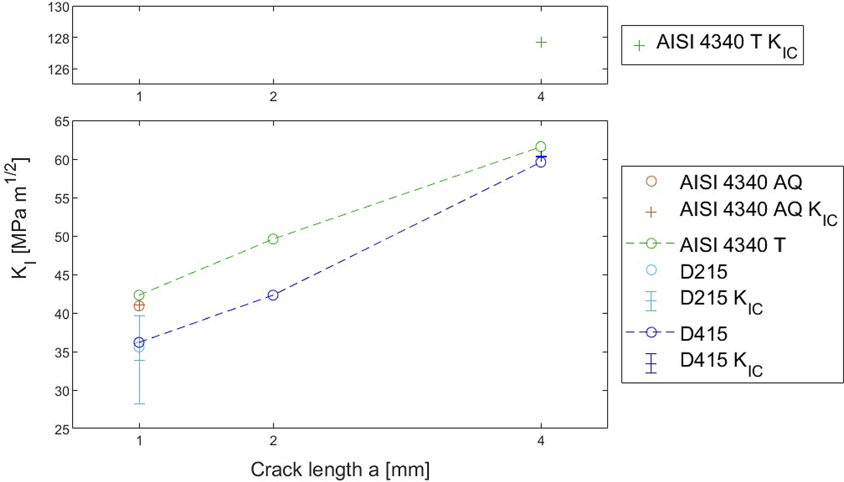
In Figure 17 a KI vs crack length graph is shown for conventional HSS and 2nd gen AHSS steels. The critical KIC value was represented by a cross and error bands were included to account for tolerances. The AISI 4340 in quenched condition and D215 steels were found in critical condition already for the 1 mm crack length. The D415 steel, instead, neared failure at 4 mm. Figure 18 shows the same kind of graph specifically for Fe30Mn9Al steels. Since a single stress-strain law for this particular steel was employed, only one curve is fitted, with each batch of steel presenting a different KIC error bar. The 1C specimen failed immediately, while both the 1A and 10 ppm of P steels failed at a = 4 mm.Only the tempered AISI 4340 and third generation AHSS specimens of the TBF1180 and Q&A type were still functional at the end of the analysis.
Concluding remarks
Recent developments in metallurgy offered novel answers to the needs of enhanced mechanical properties of metal structures in the automotive industries. High crash safety, customer satisfaction and market competitiveness are key points, and extensive research is focused on the topic. Advanced High Strength Steels are of primary importance in the design of structural components, with the newest examples being extremely competitive in terms of mechanical properties, while limiting the use of expensive alloyants.
This manuscript started by sourcing fracture toughness parameters from a series of different studies available in literature. Each one dealt with different AHSS samples, varying in chemical composition, heat treatment and fabrication technique. The data were adapted for use in a commercial FEM code, using experimental correlations to enable comparison. Such approach has not yet been adopted for this specific purpose. A reference fracture mechanics scenario was assessed, and two of the most widespread numerical techniques were adopted, the VCCT approach and the J-Integral, in order to check the consistency and to validate the model. The fracture toughness for the selected series of AHSS was estimated, and it was noted how the latest developments in third generation high-strength steels presented an unmatched fracture toughness, comfortably allowing their use in damage tolerant designs. The conventional HSS AISI 4340, when subject to proper heat treatment, also presented high resilience. Lightweight steels were instead found to be less performing in the fracture toughness department, as opposed to their excellent quasistatic tensile plastic elongation capability. Further considerations need to be made concerning the increasing interest in these steels for the automotive industry, particularly in the area of the continuous training of designers and stress analysts.
Footnotes
Acknowledgements
Activity carried out in the framework of the NextGenerationEU - National Recovery and Resilience Plan, Mission 4 Education and Research - Component 2 from research to business - Investment 1.5, ECS_00000041 VITALITY - Innovation, digitalisation and sustainability for the diffused economy in Central Italy - CUP H73C22000320001.
Funding
The author(s) received no financial support for the research, authorship, and/or publication of this article.
Declaration of conflicting interests
The author(s) declared no potential conflicts of interest with respect to the research, authorship, and/or publication of this article.