
Abstract
Pattern design plays a critical role in garment creation, serving as the foundation for virtual display, simulation, and production. In the field of whole garment knitwear, one of the primary challenges faced now is exploring efficient approaches to design patterns for custom styles rapidly. Currently, computer-aided design (CAD) systems mainly offer pattern libraries for a limited range of basic styles, such as pullovers and trousers. However, when designers are tasked with creating new products beyond the predefined libraries, designers often have to create patterns manually. This process is not only time-consuming but also heavily dependent on manual expertise, posing a significant barrier to the broader application of whole garment knitting technology. Moreover, current design systems impose limitations on pattern size modification. When specifications outside the predefined ranges are required, each pattern piece must be individually adjusted, resulting in a labor-intensive and error-prone process. To address these challenges, this study proposes a parametric design approach for whole garment pattern development based on graph theory. Subsequently, a corresponding design system was developed using C++ in Visual Studio 2022. The results demonstrate that the proposed method enables rapid pattern creation for any style that can be produced using whole garment technology, significantly reducing reliance on pattern libraries and manual expertise. In addition, the parametric design approach offers precise and flexible control over pattern size adjustments, effectively overcoming the limitations associated with traditional modification methods. This advancement greatly enhances the potential for applying whole garment knitting technology to personalized and customized garment production.
Introduction
Whole garment knitting technology is an advanced innovation that directly knits yarns into three-dimensional products, eliminating traditional steps such as fabric creation, cutting, and sewing.1,2 This revolutionary approach not only significantly reduces production costs but also transforms conventional manufacturing processes, making it a major focus of current research. However, the pattern design process for whole garment knitwear remains both complex and time-consuming, as each style requires a unique pattern-making method. In contrast, traditional garment manufacturing involves knitting separate components, such as front pieces, back pieces, and sleeves, before assembling them through stitching or other joining techniques. Thus, with traditional methods, the pattern-making process remains relatively consistent across different styles. At present, machine manufacturers have developed professional systems for whole garment pattern design, but these systems are often limited to a small set of predefined styles. More complex and diverse designs still require manual pattern development, placing substantial professional demands on designers, as demonstrated in the work of Underwood. 3 To address these challenges, Kaspar et al.4–6 developed a system capable of generating 3D machine-knittable instructions directly from traditional 2D patterns, significantly reducing the time and manual effort involved in physical production. Wang 7 explored pattern design methods for various types of whole garment knitted skirts beyond the standard pattern libraries by constructing a library of skirt design templates. These two studies present innovative solutions for pattern design: the former emphasizes a deep understanding of knitting instructions, while the latter relies on comprehensive knowledge of knitting processes. Additionally, Megan et al. 8 introduced KnitScript, a domain-specific scripting language for machine knitting that offers a complete virtual model of knitting machines. KnitScript enables users to extend its capabilities through Python programming, facilitating the development of more complex programs and user interfaces. Georges Nader et al. 9 developed the KnitKit system, which comprises two independent modules: the KnitNet generator and the machine instruction generator. These two modules work together to generate machine knitting instructions based on a triangular mesh file (.obj or .ply) and two texture images (.png), enabling the development of customized knit products. In contrast to these approaches, our work focuses on studying pattern design and process design as separate components, aiming to further streamline and simplify the whole garment pattern design process.
For knitwear, pattern design methods differ from those used for woven garments and consist of two distinct steps: pattern design and process design. 10 The former aims to create 2D patterns based on a 3D style, similar to woven garments, while the latter focuses on converting metric measurements into rows and stitches by defining vertical and horizontal density. During the process design stage, various knitting actions, such as loop knitting, tuck knitting, or float knitting, can be defined for each stitch in a garment. Currently, little research has been conducted on knitted pattern design, and most existing studies mainly focus on process design. For instance, Lu et al.11,12 investigated methods for representing knitted garment patterns, including the definition of knitting actions and the simulation of the intricate interplay among loops. These efforts laid the foundation for developing an online system that utilizes cloud-based databases for product classification and management. Such a system eliminates the need for software installation, enabling users to access it from any device and design products anytime, anywhere. 13 Additionally, researchers have explored pattern compilation files that generate machine programming instructions, as well as design approaches for fabric structures such as jacquard, intarsia, and cable patterns.14–16 It is important to note that the studies presented above primarily focused on traditional technologies and assumed that the styles and specifications had already been determined. In traditional workflows, pattern modification during the process design stage is feasible, as the procedures are relatively straightforward. However, for whole garment knitwear, such modifications become more challenging due to the complexity and diversity of the knitting procedures involved. Therefore, the most effective stage for designing and modifying whole garment knitwear patterns is the pattern design stage. In terms of pattern design, a commonly used method is parametric design. Currently, parametric design is predominantly utilized in the field of woven garments and typically involves three aspects: mathematical solutions, AutoCAD-based approaches and constraint solutions. For example, Liu et al.17,18 proposed a parametric pattern design method based on human body measurements and developed a recommendation system for jeans styles. This method enables pattern generation by inputting garment parameters and body dimensions, thereby simplifying the design process. Similarly, a woven garment pattern design system featuring an intuitive interactive interface was developed based on parametric design principles, enabling rapid customization of garment patterns. 19 Additionally, the reconstruction of 3D garments using point cloud sequences also falls within the scope of parametric design, eliminating the need to design 2D patterns. 20
However, it is important to note that the parametric design approaches mentioned above primarily rely on mathematical methods, particularly equation solving. These methods often overlook the constraints and interdependencies among various human body dimensions, leading to difficulties in constraint resolution. As a result, when parameters are modified, all related garment component dimensions must be recalculated, making localized adjustments inefficient and impractical. Another widely used approach in parametric design is based on AutoCAD, which provides a range of geometric constraint relationships—such as vertical, tangent, and collinear constraints.21–23 Nevertheless, AutoCAD is a general-purpose design tool and has limitations when applied to garment pattern design, especially for knitted garments, which involve unique and complex design processes. Therefore, it may not fully meet the specific requirements of pattern design in this domain. In addition, some studies have explored parametric design based on constraint relationships. For instance, Xiu et al. 24 developed a parametric design model for garment prototype patterns using geometric constraints. However, their model only incorporated two parameters—chest circumference and back length, thereby allowing size adjustments only. It did not consider the influence of parameters on the overall shape and structural features of the garment. Moreover, due to the simplicity of the prototype structure, only a limited number of parameters affected its design flexibility.
As highlighted in the preceding discussion, there is a significant gap in research on whole garment pattern design. To advance whole garment knitting technology, it is essential to develop a user-friendly pattern design system capable of addressing diverse design requirements. For this purpose, this study proposes a parametric design method for whole garment knitwear pattern design based on graph theory. In this approach, the relationships between parameters and geometric constraints are established for the geometric elements within the pattern. As a result, adjustments to parameters can modify both the shape and size of the pattern without the need for manual manipulation of specific parts. The results demonstrate that the proposed method enables the generation of any style compatible with whole garment knitting technology, thereby reducing dependence on pattern libraries and minimizing the need for manual adjustments. Moreover, when a specific part of the pattern is modified, the established constraint relationships ensure that the relative positions of other parts remain unchanged, thus preserving the accuracy and consistency of the overall design.
Methods of pattern design for whole garment knitwear
Characteristics of knitted pattern design
Whole garment knitwear is produced by knitting directly into a 3D form on the knitting machine. As a result, the front and back pieces of the garment may not correspond to the front and back needle beds during the knitting process. 25 Specifically, the front piece may not necessarily be knitted on the front needle bed, nor the back piece on the back needle bed. This unique knitting method is characteristic of whole garment knitwear. Figure 1 presents the knitting models for various styles created using whole garment knitting technology.

Knitting model of whole garment knitwear: (a) longitudinal knitting, (b) transverse knitting, (c) side knitting, (d) unfold knitting, (e) partitioning knitting, (f) turning knitting, (g) asymmetric knitting, and (h) interval knitting.
Figure 2 illustrates different pattern design approaches for the same style using both traditional and whole garment knitting technologies. In particular, Figure 2(c) highlights the following labels: “Front” refers to the piece knitted on the front bed, “Back” denotes the piece knitted on the back bed, and “2D pattern” represents the whole garment knitted pattern formed by merging the front and back pieces on the machine.

Pattern design methods for knitted garments: (a) 3D style, (b) pattern design methods using traditional knitting technology, and (c) pattern design methods using whole garment knitting technology.
Processes of whole garment knitted pattern design
As mentioned above, the pattern design of knitted garments typically involves two main steps. The first step is to generate a 2D pattern based on the 3D garment style; the second step involves converting the 2D pattern into a 2D knitted pattern by setting the vertical and horizontal stitch densities. In the case of whole garment knitwear, it is essential to integrate the 2D patterns of individual components into a unified 2D whole garment knitted pattern. Using the style shown in Figure 2 as an example, Figure 3 illustrates the transformation process from a 3D garment style to a 2D whole garment knitted pattern. It is evident that, for whole garment knitwear, the pattern design conducted in the initial stage plays a critical role in the overall design process, as depicted in Figure 3(a). Furthermore, it should be noted that each row in Figure 3(b) corresponds to knitting on either the front bed or the back bed, whereas each row in Figure 3(c) represents simultaneous knitting on both the front and back beds.

Processes of generating whole garment knitted pattern: (a) 2D garment pattern, (b) 2D knitted pattern, and (c) whole garment knitted pattern.
Methodology
In this work, we primarily focus on pattern design in the initial stage, with two main objectives: (1) generating 2D patterns for any style that can be produced using whole garment knitting technology, and (2) enabling precise modifications to the size and shape of the 2D pattern. Once the final 2D pattern is obtained, the corresponding 2D knitted pattern required in the second stage can be efficiently generated using the algorithms described in the work of Lu et al. 10 The main research methods adopted in this study address the following aspects.
Constructing constraint relations for geometric entities within 2D pattern
Geometric entities refer to a diverse range of geometric elements, such as points, lines and curves, that collectively constitute the pattern. In the context of geometric constraints, problems are typically formulated using geometric entities rather than geometric elements. The key of parametric design lies in establishing constraint relationships among the geometric entities presented within the 2D pattern. To illustrate this concept, Figure 4 presents a 2D pattern alongside its corresponding geometric entities.

Meaning of geometric entities: (a) 2D pattern and (b) geometric entities within 2D pattern.
In parametric design, the constraint relationships among geometric entities are generally categorized into two types: parametric constraints and geometric constraints. Parametric constraints define the intrinsic properties of geometric entities, such as length and orientation, whereas geometric constraints describe the relationships among entities, such as parallel or vertical relation. Figure 5 illustrates the constraint relationships established in this study.

Constructing geometric constraints relationship: (a) parallel constraint, (b) vertical constraint, (c) proportional constraint, (d) rotation constraint, (e) ray constraint, (f) extension constraint, (g) line & point constraint, (h) line & line constraint, and (i) line & curve constraint.
Constructing constraint graph for 2D pattern based on graph theory
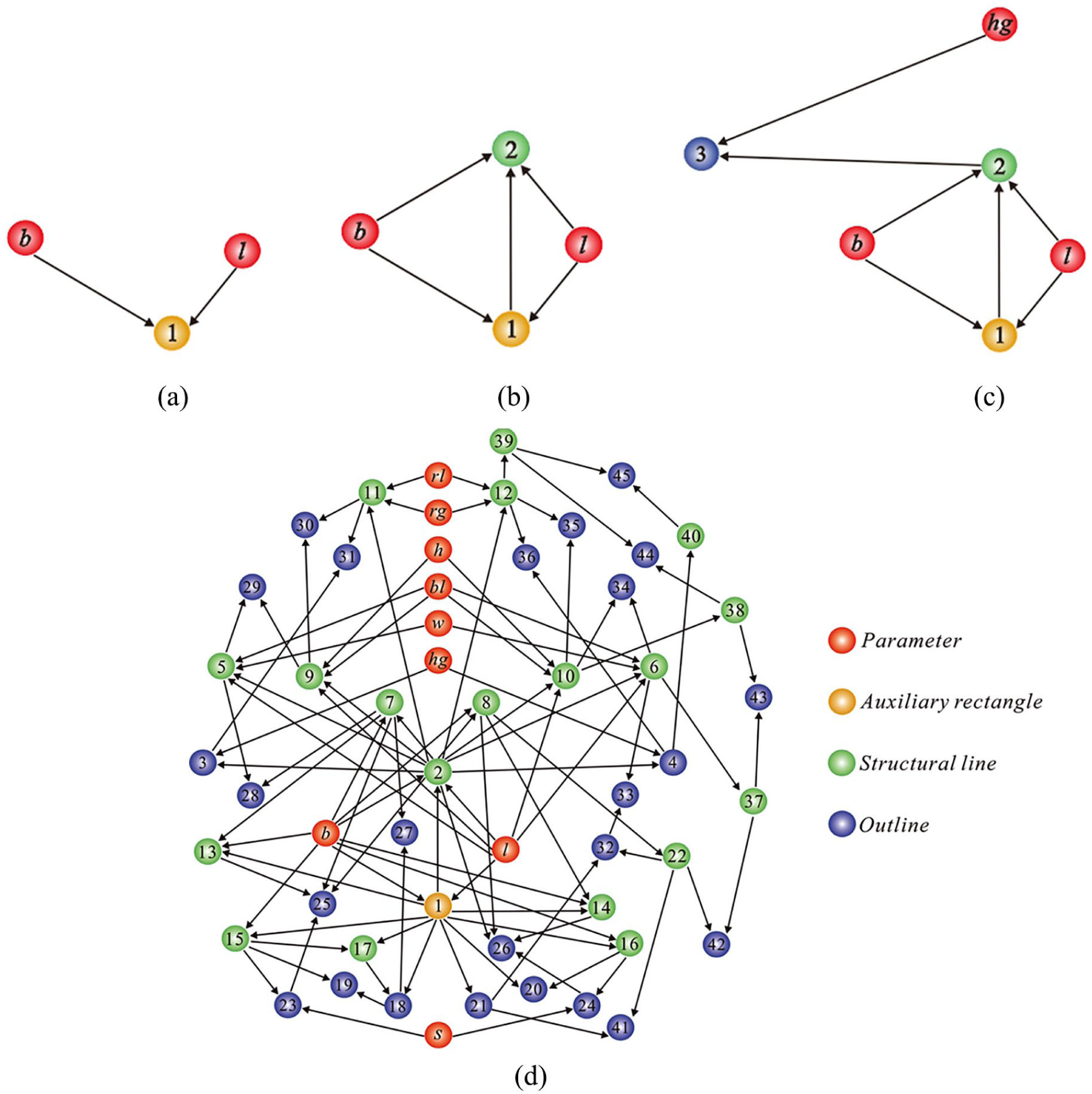
Graph theory, a branch of mathematics, focuses on the study of graphs. A graph can be defined as a mathematical structure: G = (V(G), E(G)), where V(G) is the vertex set, expressed as V(G) = {v₁, v₂, . . ., vₙ}, and E(G) is the edge set, expressed as E(G) = {(v₁, v₂), (v₁, v₃), (vₙ₋₁, vₙ)}. 26 Each edge in E(G) connects a pair of vertices in V(G), representing a specific relationship between them. If the edges in E(G) have a specific direction, the graph is called a directed graph. Conversely, if the edges are directionless, the graph is called an undirected graph. If a graph contains both directed and undirected edges, it is called a mixed graph, 27 as illustrated in Figure 6.

Definition of a graph: (a) undirected graph, (b) directed graph, and (c) mixed graph.
The relationship between a graph and a 2D pattern is that the vertices represent the geometric entities within the pattern, while the edges depict the constraint relationships among these entities. The construction of a constraint graph for a 2D pattern can be viewed as a transformation from drawing the pattern to establishing constraint relationships. For instance, based on Figure 3(a), Figure 7 presents the 2D whole garment pattern with detailed labels, enabling a more comprehensive and systematic analysis.

2D pattern with labels: (a) 2D pattern with dimensions and (b) 2D pattern with key points.
Before constructing the geometric constraint graph, it is essential to first determine the types and quantities of parameters within the 2D pattern. As previously noted, the whole garment knitted pattern is created by merging all individual components. Therefore, during the pattern design stage, each component must be designed parametrically to ensure consistency and flexibility. Table 1 presents the types and quantities of parameters used in the design of the front piece.
Parameter types and quantities of the front piece.

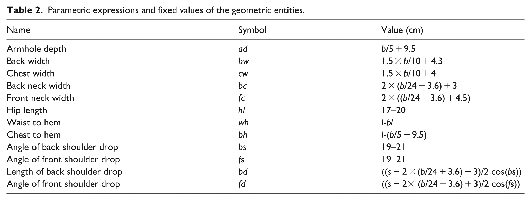
After determining the types and quantities of parameters in the 2D pattern, the next step was to define the remaining geometric entities based on these parameters. Additionally, this study assigned values to geometric entities that are independent of the defined parameters. Table 2 presents the parametric expressions of the geometric entities illustrated in the 2D pattern in Figure 7. These expressions were derived from knitted garment prototypes designed with a specific degree of looseness. The values for hip length and shoulder drop angle were determined according to commonly accepted standards.
Parametric expressions and fixed values of the geometric entities.
When constructing the geometric constraint graph, three primary types of geometric entities are typically involved: auxiliary lines, structural lines and outlines. Auxiliary lines are initially established through parameter constraints and are mainly used as guides for drafting. These lines often take the form of rectangles. In contrast, structural lines and outlines are defined using a combination of parameter constraints and geometric constraints. It is essential to incorporate all three types of geometric entities simultaneously in the geometric constraint graph. By considering the interrelationships among these entities, the graph effectively captures the full set of constraints, enabling accurate and comprehensive pattern manipulation. The specific construction process is described as follows:
The initial step in parametric design involves generating an auxiliary rectangle, denoted as geometric entity 1, based on parameters b (bust girth) and l (body length). The rectangle’s height and width correspond to body length and half of the bust girth, respectively. Taking one of the rectangle’s horizontal sides as an example, its construction is governed by a parameter constraint relation expressed as
Geometric constraint graph for the 2D front piece pattern: (a) Step 1— Initialization of geometric entities, (b) Step 2—Addition of new constraint relations, (c) Step 3—Further expansion of constraints, and (d) complete geometric constraint graph.
As depicted in Figure 8, the construction of the geometric constraint graph is closely connected with the processes of drawing the 2D pattern. Each geometric entity within the pattern is generated based on specific constraint relationships. With each step in the drawing process, new types of constraints are incrementally added to the constraint graph. Once the 2D pattern is completed, a comprehensive geometric constraint graph encompassing various constraint relationships is fully established. When modifying parameters within the 2D pattern, it is necessary to recalculate and update both the parameters themselves and their associated geometric entities. The geometric constraint graph enables rapid identification of all geometric entities connected to a given parameter. In essence, the graph captures the constraints imposed by a current geometric entity on its subsequent entities. However, it is important to note that a geometric entity influenced by a parameter may also be subject to constraints from other entities. Therefore, it is crucial to identify and update not only the succeeding entities but also the preceding ones that influence the current entity. Only by recalculating and updating both sets of related entities can a parameter modification be considered complete. When a parameter is modified, the program must traverse the constraint graph from start to finish, searching for and recalculating all geometric entities affected by the change. This process requires the creation of temporary variables to store large amounts of data, leading to significant consumption of both time and storage space.
To address this issue, this study employs the inverse constraint graph, also known as the driven constraint graph, to update the preceding geometric entities. Figure 9 illustrates the driven constraint graph corresponding to the geometric constraint graph shown in Figure 8. It is important to note that the directions between two adjacent geometric entities in the driven constraint graph are the opposite of those in the original geometric constraint graph. The primary purpose of the driven constraint graph is to facilitate the efficient identification of preceding geometric entities, thereby overcoming the challenges posed by multiple geometric influences on a single entity. By utilizing the driven constraint graph, the search process is significantly optimized, reducing computational complexity and minimizing the demands on time and memory resources.

Driven constraint graph for 2D pattern of the front piece.
Constructing constraint solving data model
The primary goal of parametric design is to solve constraint relationships among geometric entities. These solution processes rely on the constraint graph and its corresponding data model. In this study, the C++ Standard Template Library (STL) was utilized to build the data model for constraint solving within the 2D pattern design, including the construction of both the geometric constraint graph and the driven constraint graph.
Geometric constraint data model
The geometric constraint data model plays a critical role in locating succeeding geometric entities and is implemented through the geometric constraint graph. Its data structure is defined as std::map<id, CVertex*>, where id represents the identifier of a parameter or geometric entity, and CVertex* denotes a pointer to the geometric entity class. In this way, the parameter or geometric entity associated with a specific id can be accessed via the corresponding CVertex* pointer. The diagram in Figure 10 illustrates the data storage structure of std::map<id, CVertex*>. Additionally, each geometric entity uses a data structure vector<CVertex*> m_ConstraintRelationTo to record the entities it directly influences, with each row in Figure 10 representing such relationships. For example, when the parameter l is modified, it will trigger changes in geometric entities 1, 2, 5, 6, 9, and 10.

Diagram of geometric constraint data storage: (a) data storage of geometric constraint and (b) data storage of parametric constraint.
The process of solving constraints using this data model can be described as follows. When the value of bl is modified, its address is stored in the vector<CVertex*> m_ConstraintRelationTo. This change subsequently triggers updates to geometric entities 5, 6, 9, and 10, which will be added to the vector using the push_back function. As a result, the vector will be updated accordingly. Next, a sequential traversal is performed on geometric entities 5, 6, 9, and 10 to search for the entities directly connected to them. Specifically, geometric entity 5 influences entities 28 and 29; entity 6 influences entities 33 and 34; entity 9 influences entities 29 and 30; and entity 10 influences entities 34 and 35. Therefore, the vector is further updated by inserting entities 28, 29, 30, 33, 34, and 35.
Driven constraint data model
The geometric constraint data model enables the search for succeeding geometric entities influenced by the current one. However, it does not support the search for preceding geometric entities that constrain the current entity. When a geometric entity is modified, it is necessary to update both its succeeding and preceding entities. Therefore, establishing a driven constraint data model becomes essential. The driven constraint data model, which is used to identify the geometric entities imposing constraints on a given entity, is realized through the driven constraint graph. Similar to the geometric constraint graph, its data structure also uses std::map<id, CVertex*>, and its storage structure is illustrated in Figure 11. In addition, a data structure named vector<CVertex*> m_ConstraintRelationFrom was introduced in this study to store the incoming constraints for each entity, corresponding to each row in Figure 11.

Diagram of driven constraint data model.
Taking the example mentioned above to illustrate the process of solving driven constraints. As shown in Figures 10 and 11, the parameter bl affects geometric entities 5, 6, 9, and 10, which are constrained by geometric entity 2. Therefore, geometric entity 2 is stored in the vector < CVertex * > m _ constraint From. Therefore, after modifying the parameter bl, the geometric entities that need to be recalculated include entities 2, 5, 6, 9, 10, 28, 29, 30, 33, 34, and 35. By constructing the constraint relationships among these entities and utilizing the constraint data model, this method achieves local constraint solving, avoiding a full traversal from beginning to end. As a result, it significantly improves computational efficiency while simultaneously reducing memory consumption.
Result and discussion
Application of parametric design in pattern grading
Grading refers to the creation of a series of patterns in different sizes by setting size difference based on the basic pattern. To accommodate individuals with diverse body shapes, multiple size specifications of a single pattern are often required in practical production. In a Computer-Aided Design system for woven garments, there are typically three main modules: pattern design, grading design, and layout design. Although these systems provide grading functionalities, designers must possess a solid understanding of grading principle, such as point grading, line grading, and equal grading, as well as proficiency in system operations. This demands considerable technical expertise and professional knowledge. In contrast, knitted garment pattern-making systems usually offer predefined specifications that can be directly applied. However, due to inherent limitations, these specifications often fail to fully meet practical needs. The parametric design approach proposed in this study offers an effective solution to this problem. By adopting parametric design, designers can quickly adjust pattern sizes by simply modifying parameter values, without being restricted by traditional grading rules. This approach not only simplifies the grading process but also significantly enhances the efficiency of pattern-making. Accordingly, the following section explores the application of parametric design in pattern grading.
Figure 12(a) shows the user interface of the parametric design system, where “basic” refers to essential parameters, “advanced “ represents optional parameters, and “special body shape” indicates dimensions for specific body parts that do not affect overall body structure, such as front and back shoulder slopes. This enables the generation of customized patterns for individuals with unique body shapes. By inputting the parameters into the edit box and clicking the button “OK”, a complete pattern can be generated. Figure 12(b) presents a 2D pattern created based on the parameter values shown in Figure 12(a).

Parametric design interface and 2D pattern.
By grading in the same proportion, the proportion editing box in Figure 12(a) enables users to generate patterns of any desired size based on the basic pattern. As shown in Figure 13, Figure 13(a) illustrates the patterns obtained by scaling the basic pattern at ratios of 1.2 and 0.8. In this figure, the “red pattern” represents the basic pattern, the “dark blue pattern” corresponds to the pattern scaled by a factor of 1.2, and the “light blue pattern” represents the pattern scaled by a factor of 0.8. Furthermore, localized adjustments to the pattern can be achieved by modifying individual parameters. For instance, changes in body length primarily affect the overall length of the garment, as shown in Figure 13(b). Variations in bust girth influence the armhole depth, back width, and chest width, as illustrated in Figure 13(c). Similarly, modifications to back length alter the waist contour at normal, high, or low positions, as depicted in Figure 13(d).

Influence of a single parameter on modeling: (a) grading in the same proportion, (b) influence of body length on modeling, (c) influence of bust girth on modeling, and (d) influence of back length on modeling.
Application of parametric design in garment modeling
After analyzing the application of parametric design in pattern grading, this study further explores the simultaneous influence of multiple parameters, including waist girth, hip girth, shoulder width, rib girth, and hem girth, on garment modeling. Figure 14(a) illustrates the initial garment style along with its corresponding pattern, while Figure 14(b)–(f) respectively show five different garment styles and their associated 2D patterns, which are generated from Figure 14(a) by adjusting the parameters listed in Table 3. Figure 15 shows the 2D pattern corresponding to the knitting model presented in Figure 1.
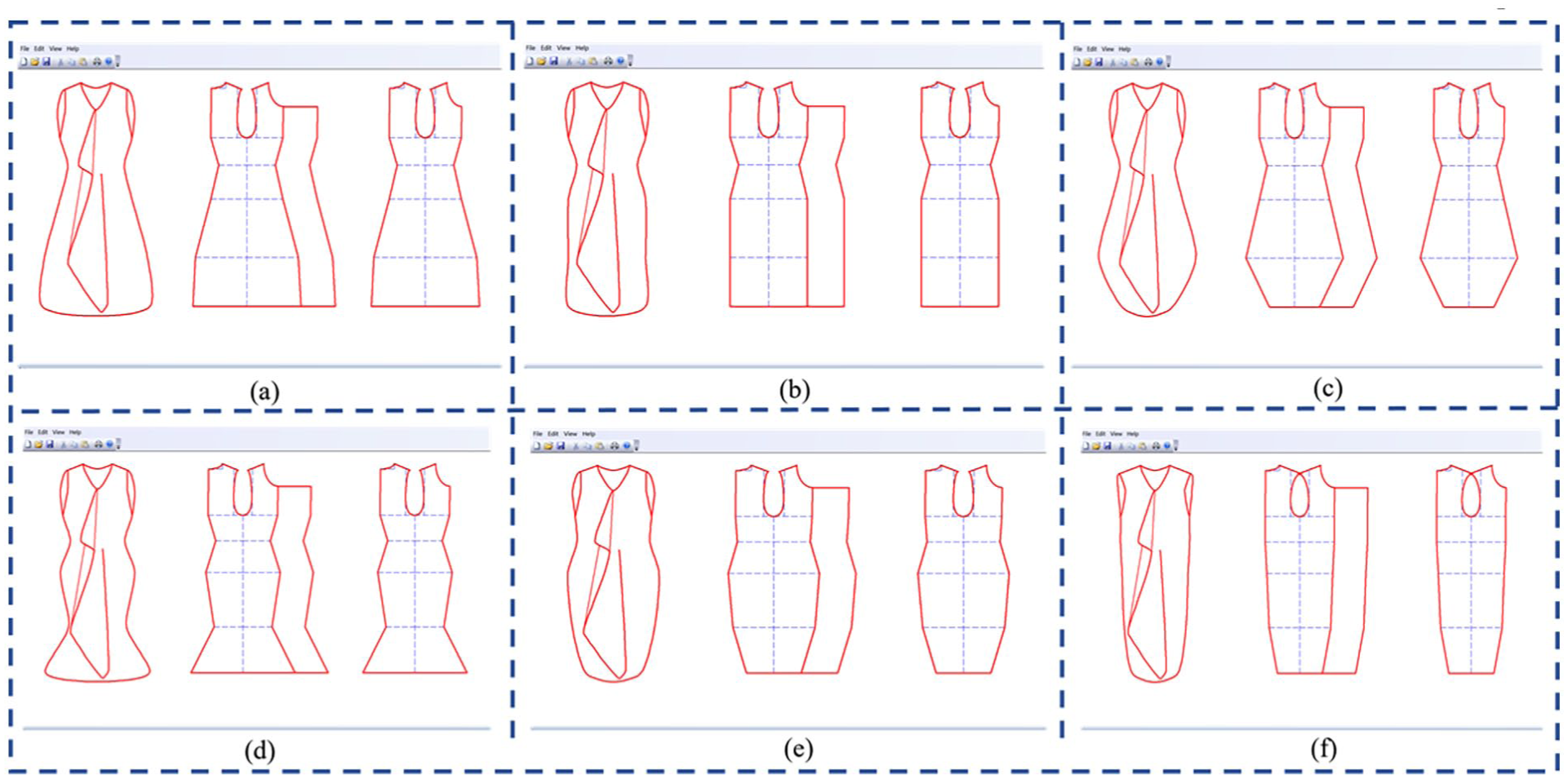
Influence of multiple parameters on modeling: (a) initial style, (b) style variation 1, (c) style variation 2, (d) style variation 3, (e) style variation 4, and (f) style variation 5.
Influence of different parameters on modeling.


2D pattern of whole garment knitwear: (a) longitudinal knitting, (b) transverse knitting, (c) side knitting, (d) unfold knitting, (e) partitioning knitting, (f) turning knitting, (g) asymmetric knitting, and (h) interval knitting.
Conclusions
In this study, a parametric design method for pattern design of whole garment knitwear was proposed. This approach effectively addresses the challenges encountered in modeling design and size modification for whole garment knitwear. As illustrated in Figure 13(a), parametric design allows for synchronous grading through adjusting the parameter proportion, enabling the rapid generation of patterns in various sizes. This innovation significantly reduces the designers’ workload. Moreover, parametric design also facilitates garment modeling changes. As illustrated in Figure 13(b)–(d), local modeling changes can be efficiently achieved by adjusting specific parameters, while preserving the original constraint relationships in the unaffected parts. In addition, overall garment modeling can be rapidly altered by adjusting multiple parameters simultaneously, eliminating the need to create separate patterns for each new style, as demonstrated in Figure 14.
The advantages of parametric design stem from three key aspects. First, it overcomes the heavy reliance on traditional pattern libraries and manual expertise. In this method, constraint relationships are established based on the geometric elements of garment patterns, independent of specific garment styles. As a result, the system can generate patterns for any style that can be realized through whole garment knitting technology, as demonstrated in Figure 15. Second, pattern size modifications are made remarkably straightforward. Designers can easily adjust the size of one or multiple sections simply by changing parameter values, without the need to manually recalculate the dimensions of related parts. Third, the method ensures high accuracy and consistency in pattern-making. Thanks to the established constraint relationships, when the size or shape of one part is altered, the relative positions of other components remain unaffected. In conclusion, the implementation of parametric design effectively addresses the issues associated with modeling changes and size modifications in whole garment knitwear pattern development. The system developed in this study shows great potential for creating personalized and customized garments utilizing whole garment knitting technology. The results validate both the correctness and feasibility of the proposed methods.
Footnotes
Funding
The authors disclosed receipt of the following financial support for the research, authorship, and/or publication of this article: This work was supported by the Science and Technology Innovation Program of Wuhan Textile University (253025) and the Doctoral Research Start-up Fund of Wuhan Textile University (255147).
Declaration of conflicting interests
The authors declared no potential conflicts of interest with respect to the research, authorship, and/or publication of this article.