
Abstract
In this work, it was aimed to develop carbon fiber reinforced epoxy thermoset resin composite tapes for flexible rapier weaving machines. Five different types of epoxy resin (Flex, Norm Medium, Norm Slow, Norm Hard and MGS-LR) and three different types of carbon fabric (200 g/m² plain weave, 200 g/m² unidirectional and 300 g/m² unidirectional) were employed. For laminate production, vacuum assisted resin infusion method was used. The number of carbon fabric layers and their placement or direction in the reinforcement were also changed to obtain different composite properties. It was calculated based on rapier dynamic motion analysis that rapier tapes were subjected to maximum around 500 N at 800 rpm running speeds and below 300 N under 600 rpm industrial running speeds. Load elongation and 3-points bending tests were applied to composite samples. The results were evaluated and compared with the results of a commercially used carbon reinforced composite rapier tape. It was shown with the solution of dynamic rapier motion analysis and load-elongation curve measurements that elongation under 0.1 mm at 500 N was obtained for a 150 mm sample length which is close to commercial rapier tape. Although bending force was calculated well below its breaking value when it is bent to 150–200 mm radius of curvature (radius of rapier drive wheel) for a sample length of 150 mm, both maximum bending force and maximum bending strength values remained under those of commercial composite rapier tape and needed improvement with further studies.
Keywords
Introduction
Weaving process is the best known and the oldest fabric formation method in human history and different weaving machines were developed for producing woven fabrics of various types since the first industrial revolution. A woven fabric is produced by three primary and two secondary motions of a weaving machine. Weft insertion mechanism is the most critical motion among three primary motions as it determines weaving machine production speed. From the shuttle picking system (the first commercial system) to shuttleless weft insertion systems (projectile, rapier, air jet and water jet systems), loom production speeds increased with decreased mass of weft carrier. For this reason, air jet and water jet looms have the highest production rates. Rapier weaving machines, on the other hand, are the most versatile and most widely used looms in textile industry. Rapier heads which hold weft yarn and carry it in the shed are moved by either flexible tapes or rigid rods. Both rigid rods and flexible tapes are designed and manufactured as composite materials today to reduce their mass and try to increase loom production speeds. Flexible tapes are preferred by majority of loom manufacturers due to a lower overall machine width compared to using composite rods.
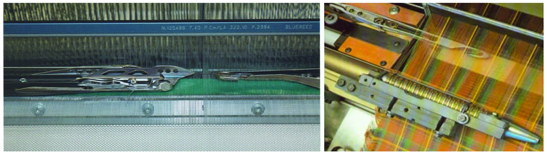
Figure 1 shows operation principle of a flexible rapier weft insertion system. There are two wheels on the right- and left-hand side of the loom driving the rapier tapes. In Figure 1(a), rapiers from both sides are driven toward the middle of the shed. When they meet in the middle, weft is transferred from the giver rapier to the taker. Then rapiers are pulled back out of the shed by the reverse motion of the wheels (Figure 1(b)). The shed is changed, and warp yarns hold the inserted weft. Finally beat up takes place and the inserted weft is carried to the cloth fell. This process continues in each loom revolution. As seen from the Figure 1, rapier tapes are wrapped around the wheels due to their flexible structures. During their course of motions, both rapiers move partly outside the shed and mostly inside the shed. Irrespective of the type of flexible tapes, both rapiers are guided outside the shed. Except carbon reinforced composite tapes, other types of rapier tapes are also guided inside the shed.

Flexible rapier weft insertion system: (a) forward motion of rapier bands, (b) backward motion of rapier bands. 1
Since its introduction to industry, loom manufacturers have used different types of flexible tapes in their designs such as plastic tape, cotton fiber reinforced composite tape and carbon fiber reinforced composite tapes. As was explained above, all the tapes are guided outside the shed by special guiding elements to direct rapier straight to the shed. As rapier tapes move inside the shed half the reed width, a straight motion of them must be provided. Otherwise, there might be loom stops due to weft transfer problems in the middle of the shed. To satisfy this condition, tapes are guided on the reed by small metal guide elements spaced with some distances like 30–50 mm in some rapier weft insertion system designs. Two different tape guide systems used in industrial flexible rapier weaving machines are shown in Figure 2. Both systems employ tapes other than carbon reinforced composites because the structure of plastic and cotton fiber reinforced composites require this guidance to keep tape motion straight and conduct a proper weft transfer in the middle of the shed. In the case of using carbon reinforced composite tapes, no guide elements are employed on the reed because carbon reinforced composite tapes can follow a motion on a straight line at speeds exceeding 600 rpm (Figure 3) due to their higher bending rigidity.

During weaving process, metal guide elements on the reed will always be in friction with moving warp yarns as well as tapes. As a result, metal guide elements and warp yarns are abraded. This causes yarn breaks and/or woven fabric faults which reduce loom efficiency due to stops and increases the amount of second quality fabric. Also, the metal guide elements on the reed might produce line marks on the fabric woven especially with high warp densities. Therefore, they are not desired from weaving technology point of view. Carbon reinforced composite tapes have the advantage of requiring no guide elements and are getting more widely used. Although the carbon reinforced composite tapes are more expensive, they have longer service life which balance the cost disadvantage compared to other types of flexible tapes.
Technical requirements of the rapier tape
Carbon fiber reinforced composite tapes are developed to run flexible rapier looms at high operating speeds without guides on the reed. This is called free fly rapier technology. There are certain requirements of the rapier tapes for the efficient running of a flexible rapier loom. These are listed below.
- Rapier acceleration and therefore inertia force affecting to tape is generally at its maximum value around weft transfer instant from the giver to the taker rapier in the middle of the shed. Weft transfer adjustment between two rapiers is carried out while the loom is at standstill, that is, under static conditions. It is expected that the same weft transfer conditions prevail during running of a loom, that is, under dynamic conditions. It is an important requirement that rapier tapes do not elongate under the effect of forces to deteriorate weft transfer conditions. Hence as the first requirement, it can be stated that the composite rapier tape should have as high elastic modulus as possible.
- Bending resistance of the rapier tape should also be high so that the rapier tape moves on a straight line in the shed and the giver and taker rapiers meet at correct transfer position.
- Heat resistance of the tape should be as high as possible so as not to increase its temperature during machine running and friction with machine elements.
- Coefficient of friction of tape surface should be as low as possible.
- High fatigue resistance and high interlaminar shear strength are other parameters that a rapier tape is expected to satisfy.
No defined specific values of the above parameters were found in the scientific literature. But critical bending strength and bending modulus values of composite rapier tapes were given by a commercial producer of rapier tape as ⩾150 MPa and ⩾4.5 GPa respectively. 5
When the literature is reviewed, a limited amount of research was found on this specific topic. But there are some patents in the patent literature. These are summarized below.
Wei and Chen reviewed composite material applications in textile machinery including fiber reinforced composite rapier head and rapier tapes. They reported that the composite material for rapier weft insertion system should be not only light weight and high strength, but also abrasion resistant. 6 They also cited three research papers related to composite rapier tape development. Wang and Huang tried to produce composite material for rapier head and flexible rapier tape by using carbon fiber reinforcement of HBS-3 resin matrix material using wet winding molding method and they conducted static and dynamic performance tests. 6 They concluded that composite rapier’s weight was 0.1 kg and produced noise lower than 8 db. They further concluded that rapiers had long service life, reduced downtime, maintenance frequency. Zhou developed and produced rapier components by injection molding process using glass fiber reinforced nylon matrix. 6 He concluded that composites showed a good heat resistance, low coefficient of linear expansion, excellent resistance to creep and fatigue and the heat distortion temperature above 170°C. Also, weft insertion rate of 1000 m/min or over was reached by the developed rapier components. China Aerospace developed and manufactured a flexible rapier tape by employing an epoxy matrix reinforced with chemical fiber in 1990. 6 It was concluded that the developed rapier tape showed a good anti-friction and fatigue resistances and met the mechanical, physical, and thermal corrosion requirements of weft insertion. Xie studied the production of rapier heads. 6 They developed carbon fiber reinforced thermoplastic composite material using nylon 6, nylon 66 and nylon 1010 matrix. It was concluded that 25% carbon fiber content of nylon resin-based composite met the requirement of running process. No specific detail was given in these publications as to whether flexible rapier tapes were tested with or without guides in the shed.
It is indicated in a patented study that flexible band was made of fiber reinforced synthetic resin. A composite rapier tape was designed a two-part band. The second part was made of a composite material which had a higher rigidity than the first part wound around a band wheel. Reinforced phase fibers included carbon fibers, glass fibers, inorganic fibers and the like, while matrix materials included epoxy resin, phenol resin, urea resin and melamine resin as thermosetting secondary sides. It was mentioned that unsaturated polyester, polyimide, and polyamide resins could be used as thermoplastic resins for matrix material. 7 In another patented study, a 3D braiding fabric was used as reinforcement. The resin was impregnated into the fabric by placing it in a mold with protrusions on it. High elastic modulus fibers, such as carbon and ceramic fibers, were used as reinforcing fibers. A thermosetting epoxy resin was absorbed into the fabric by the resin transfer method and the composite material was produced this way. 8 The other patent published as a follow-up to this included some improvements. It was mentioned that polyaramid and carbon fiber were used together. 9 A flexible rapier tape was produced by placing fabric layers on top of each other in the other patented study. Bottom and top layers were used as carbon woven fabric with satin weave. Carbon fiber was preferred because of its high abrasion resistance. In between top and bottom carbon layers (middle layer) a 3D woven carbon fabric was used. 10 A composite rapier tape was designed and produced to eliminate rapid wear and short service life due to friction. Molybdenum disulfide filler was used in the mixture of epoxy and phenol formaldehyde resin as a lubricant against friction-induced wear. Lavsan fabric was used as a reinforcement in 0.1–0.25 mm thickness in 48%–52% volume ratio of the composite. 11 In another patented development, epoxy resin pre-impregnated polyester fabrics, epoxy resin pre-impregnated carbon fiber fabrics and a layer of filled polytetrafluoroethylene film were placed sequentially on top of each other. Carbon fiber fabric is filled with a single membrane of polytetrafluoroethylene, placed between two adjacent layers of polyester fabric. The vacuum bag was prepared by placing it in the strip size mold and the preform inside the sealed bag was cured into a laminate. 12 A patent explains a study on resin hardening agents and its synthesis. The curing agent was prepared by carrying out a reaction on the following components: acetone, vulcanizing agent, 4,4’-diamino diphenyl ether, 3,3’- diamino diphenyl sulfone, epoxy resin and 3,3’-dichloro-4,4’-diphenylmethane diamine. Preferably the epoxy resin was composed one or more of epoxy resin F44, epoxy resin 6101 and epoxy resin E51. Polyether amine was used as a softening at a ratio of 0.5%–1.5% by weight. Acetone was used as the solvent. Epoxy resin was chosen due to its superior mechanical, electrical and environmental resistance properties. After the studies, flexible rapier tape was produced as a composite material, which had good wear resistance and fatigue resistance, high bending strength, compression resistance, tensile strength, impact resistance, strong heat resistance and long service life. 13 A composite rapier tape was designed to eliminate heat problems caused by friction. In a patent application for flexible rapier tape, carbon fiber was used as reinforcement material and polyester or polytetrafluoroethylene composite resin material. It was mentioned that there may be a pultrusion production made of carbon fiber and glass fiber. 14
In this research, an attempt has been made to develop carbon reinforced composite rapier tapes suitable for use in free flight (without guide on the sley) rapier weft insertion system. Dynamic rapier motion analysis was carried out to calculate the force affecting the rapier tape during rapier motion. Bending equation is also presented to calculate bending force to bend and wrap the rapier tape around drive wheel. In the early stage of experimental work, a composite rapier tape already used in industry was subjected to tests to determine reference design criteria like load-elongation and bending force-deflection curves. Then, carbon fabric type and weight per unit area, number of carbon fabric layers and resin type were taken as main parameters in developing carbon reinforced rapier tapes. Load elongation and bending behaviors were focused on satisfying the first 2 minimum requirements given above as they are of higher priority for composite rapier tape operation. The buckling possibility of rapier tape during its motion was also investigated.
Materials and methods
Materials
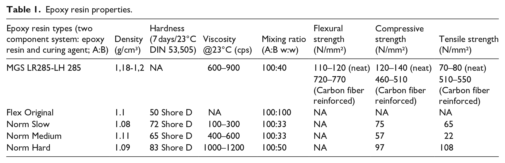
Five different types of epoxy resins were used as matrix: MGS LR285 resin and LH285 hardener from Hexion, USA; Resinin Flex Original, Resinin Norm Slow, Resinin Norm Medium and Resinin Norm Hard epoxy resins from Marker Chemistry, Türkiye. Carbon fiber reinforced epoxy resin composites have many advantages and have been widely used as structural material applications because of their excellent specific strength, elastic modulus, light weight and ease of molding.15,16 Advanced composites which made from carbon fabric/epoxy layers offer superior performance over metallic alternatives. 17 Due to this compatibility, different epoxy resin types were chosen as the matrix material. Resin properties are given in Table 1.
Epoxy resin properties.
Three different types of carbon fabric were employed as reinforcement: 200 g/m² plain weave carbon fabric from DowAksa, Türkiye; 12 K 200 g/m² undirectional (UD) carbon fabric and 12 K 300 g/m² unidirectional (UD) carbon fabric from Dost Chemistry, Türkiye. Figure 4 shows three different carbon fabric pictures.

Carbon fabric reinforcement types: (a) 300 g/m² UD carbon fabric, (b) 200 g/m² plain weave carbon fabric, and (c) 200 g/m² UD carbon fabric.
Method
Fabrication of composites was performed using vacuum assisted resin infusion process. CVP-50 model, 0.3 Pa ultimate vacuum and 1 HP power vacuum pump from Cacheng, China was used in the set up. Laminate size was taken as 450 mm × 250 mm. The whole lay-up was vacuum-bagged and was left to cure for 24 h at normal room temperature. Final curing was completed after 7 days. The details of the composition of composites and laminates produced are as shown in Table 2.
The details of the composition of composites and laminates produced.

The hardener was added to epoxy resin in the weight ratio as indicated in Table 1. It was slowly stirred for 5 min by hand until a homogeneous and smooth image was obtained. The most critical phase in this production technique is to guarantee the vacuum throughout the curing stage. This was ensured by vacuum check on the vacuum bag setup before starting the infusion process. Once the vacuum check was over, the infusion process was started and controlled with the help of control valves in the inlet and exit tubes. Vacuum pump was run around 90 min. Whole composite sheet was allowed to cure for 24 h under pre-induced vacuum condition of 1 bar. The vacuum assisted resin infusion setup and produced laminate sample are shown in Figure 5.
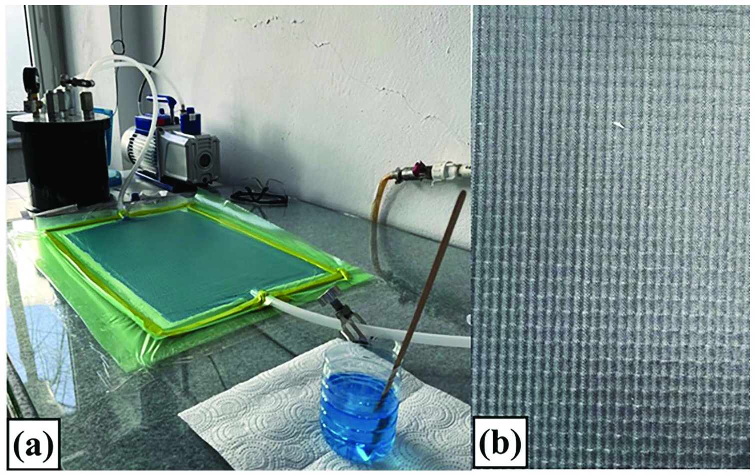
Composite production elements: (a) vacuum assisted resin infusion setup, (b) produced laminate sample.
Characterization
Tensile test
Ep/CF composite samples were prepared as per ASTM D3039 standard. Rectangular samples of dimension 250 mm × 30 mm were prepared, the gauge length was fixed to 150 mm, and tensile tests were performed on Shimadzu Universal Testing Machine (Type AGX-HS, 5KN capacity) at a displacement rate of 2 mm/min. Three samples were used for each test’s repetitions.
Flexural test
Ep/CF composite samples were prepared as per ASTM D790 standard. Rectangular samples of dimension 70 mm × 30 mm were prepared, the distance between supports was fixed to 50 mm and three-point bending tests were conducted using Shimadzu Universal Testing Machine (Type SLFL, 100 kN capacity) at a test speed of 2.67 mm/min. Three samples were used for each test’s repetitions.
Testing machines, tensile and bending test samples are shown in Figure 6.

Testing machines and test samples: (a) tensile testing device, (b) bending testing device, and (c) tensile and bending test samples.
Motion analysis of rapiers
Two rapiers carry out a very similar motion but in opposite direction. During running, the forces affecting in the direction of tape are rapier inertia force, yarn tension and frictional forces between rapier and rapier guide outside the shed. Yarn tension force is ignored because it is very small (maximum around 1–2 N). But force of inertia is the main force affecting rapier tape. Rapier inertia force is calculated below based on rapier dynamic motion equation. Friction force between rapier tape and metal guides outside the shed are calculated from bending force and coefficient of friction between metal guide and rapier tape.
Although rapier drive mechanisms are designed for an optimized motion curve, it can be represented by simple harmonic motion for the simplicity of calculations. Considering 1900 mm reed width and 250 mm rapier motion outside the shed, the total rapier displacement can be calculated as the sum of rapier motion outside the shed and rapier motion inside the shed (half the reed width) which amounts to around 1200 mm. Rapier motion is mainly determined by the rapier drive wheel. Rapier tape elasticity also contributes to the actual rapier motion due to its elongation under the influence of especially inertial forces during its motion. Considering the high elastic constant of rapier tapes, its effect on rapier displacement might be in the order of a few mm. But this can cause problems during weft transfer and should be allowed for in the rapier tape design.
The physical model in Figure 7 can explain rapier motion which includes motions due to rapier drive wheel (

Rapier motion model.

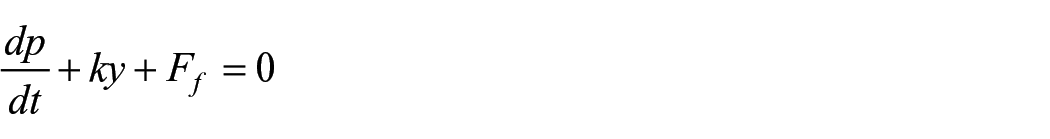


Equation (1) can be written as follows in a detailed form.

Rapier mass in motion can be expressed as below with equation (3). Therefore, its derivative can be written with equation (4).


After necessary arrangements, equation of rapier motion can be written with equation (5).


Equation (5) is arranged for

During the motion of the rapier, the force affecting the rapier tape is balanced by rapier tape elastic force (ky) and is the sum of inertia and frictional forces. Compared to statical analysis, an additional force component is included in the equation as
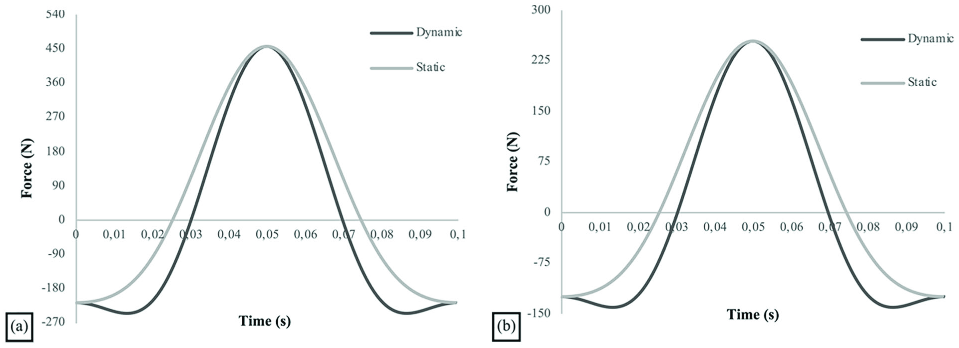
Force affecting rapier tape during its one revolution: (a) for 600 rpm, and (b) for 800 rpm.
It is assumed that rapier drive mechanism operates according to simple harmonic motion as given below with equation (7) and equations (8) and (9) are the first and second derivatives.
Rapier displacement due to drive wheel

Rapier velocity

Rapier acceleration

For a 1900 mm wide rapier loom running at 600 and 800 rpm, the force affecting the rapier tape during one loom revolution has been calculated using the above equations and shown in Figure 8. Force calculated from static analysis (F = ky = m
Bending is another important parameter in the design of rapier tapes because rapier tapes are bent and wrapped around the drive wheel of certain radius. Critical bending force determines the bending radius. Increasing the elastic constant will make it more difficult for the tape to be bent. Higher elastic constant is required to move the rapier tape straight in the shed and with minimum elongation especially during weft transfer in the middle of the shed. Therefore, there must be a compromise between higher elastic constant and bending radius of the tape. Equation (10) explains the relationship between bending radius, bending moment, elastic modulus and secondary moment of inertia of a material. 19 For a desired bending radius and given elastic modulus and secondary moment of inertia of the tape, bending force can be calculated and compared with breaking force obtained from 3-point bending test. In the Results part, bending tests results are presented and breaking force is compared with the calculated bending force for the desired bending radius.
r: Radius of curvature.
I: Secondary moment of inertia (m4)
M: Bending moment (=F.L/4, Nm)
Moment of inertia of a rectangular cross-section member is calculated as equation (11) below.

b: Width of the section (m)
t: Thickness of the section (m)
Elastic modulus is calculated by equation (12) below.

E: Elastic modulus (N/m2)
F: Force (N)
A: Cross-sectional area (m2)
ΔL: Elongation (m)
L₀: Original length (m)
Buckling is also an important parameter in composite rapier tape design. The force that causes buckling of a rapier tape was measured experimentally by applying compression test to the composite tape samples with 150 mm length. The forces causing buckling was measured and compared with the force affecting the rapier tape during rapier motion (Figure 8).
Results and discussion
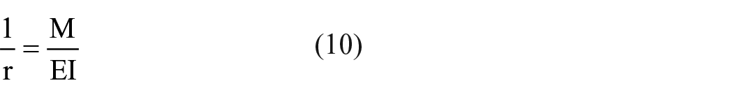
Experimental research program was designed to investigate the effect of epoxy resin type, carbon fabric layer, fabric layer direction and carbon fabric type on tensile and bending properties of composite material aimed at using as rapier tape. Table 3 shows 23 different composite sample parameters. As was mentioned in material part, five different resin types, three different carbon fabric types and two different fabric placement directions were used in the experimental work.
Composite sample parameters.
Thickness and weight
Table 3 shows average thickness, average weight and fiber ratios for 23 composite samples. The average tape weight was calculated based on dimensions of the commercial tape. The length of commercial tape used as reference in this study is 2200 mm, its thickness is 1.33 mm and its width is 27 mm. It is perforated as 164 holes, with 5 mm × 7 mm size. Its weight was measured as 107 gr. As seen in Table 3, the composite tapes produced with reinforcement of 200 g/m² plain weave fabric with 5 layers; 200 g/m² UD fabric with 5 and 6 layers and 300 g/m² UD fabric with 4 layers approached the commercial tape thickness and weight.
Tensile properties
Effect of number of fabric layer on load elongation curves of composite rapier tape
Figure 9(a) shows load elongation curves of carbon reinforced composite tape produced with flex epoxy resin (FER) and 2, 3, 4, 5 layers of plain weave carbon fabric. As seen from the curves, slope of initial region increases with increasing number of fabric layer. This corresponds to a higher modulus. Considering a 500 N maximum force affecting to the tape in it is longitudinal direction, elongations become 0.64, 0.42, 0.22, 0.18 mm respectively as the number of fabric layers increase from 2 to 5. All the curves demonstrated linear increase up to 1250 N force.

Load elongation curves of S1, S2, S3, S4, S6, S8, S9, S10, S11, S13, S15, S17 and S18: (a) S1, S2, S3 and S4, (b) S6, S10 and S11, (c) S8 and S9, (d) S13, S15, S17 and S18.
In Figure 9(b), load elongation curves of composite tapes are presented for 4, 5 and 6 fabric layers. Composite tapes were produced in this case with medium epoxy resin (MER) reinforced by 4, 5, 6 layers of plain weave carbon fabrics same as that of Figure 9(a). In all three curves there is a linear increase up to 1500–1750 N force. The slope or modulus of composite tapes increases with increasing number of layers. Elongations at 500 N decreased in the order of 0.18, 0.15 and 0.11 mm with number of layers increasing as 4, 5 and 6. This result shows that changing composite matrix from FER to MER significantly decreased the elongations and increased modulus of the composite tapes. This is a desired property for a rapier tape because it decreases elongation of the tape in the middle of the shed during weft transfer.
Another experiment was conducted by mixing MER and hard epoxy resins (HER) with 50:50% ratio. Reinforcement fabric was taken as plain weave carbon fabric of the same as above. Figure 9(c) shows the load elongation curve of these composite tapes. Here too, modulus increased with increasing number of fabric layer. Elongations at 500 N decreased from 0.17 to 0.14 mm with the number of fabric layers increasing from 4 to 5. These values are 0.01 mm lower than composite tapes produced with same fabric type and layers but with MER.
In Figure 9(d) load elongation curves of composite tapes are presented for 3, 4, 5 and 6 layers of UD 200 gr/m2 carbon fabrics. In this case too, MER was used as matrix material. In the reinforcement UD fabrics of 3, 4, 5 and 6 layers were employed. UD fabric was preferred in these experiments to see the effect of absence of crimp on load elongation curve of the composite tape. Load elongation curves show linear change up to 1500–1750 N force. Elongation values at 500 N are 0.17, 0.17, 0.13, 0.08 mm for 3, 4, 5 and 6 layers respectively. Compared to Figure 9(b) obtained with plain weave carbon fabrics there is a decrease in elongations for the same force (500 N) with UD fabric use. For 6 layers of fabric, elongation at 500 N decreased from 0.11 mm to 0.08 mm. This is an expected results due to the absence of crimp in UD fabrics and has an advantage for weft transfer conditions because of lower elongation under inertial forces.
The above results show that the elongation of the composite tapes decreased with number of layers in all resin types. Composite tapes produced with UD fabrics showed higher modulus and lower elongation due to the absence of crimp in the fabric structure. With all resin types, the initial modulus increased, and elongation decreased with increasing number of fabric layer. As fiber content increased, the mechanical properties increased.20,21
Effect of fabric layer placement on load elongation curves of composite rapier tape
Figure 10(a) shows load elongation curves of composite tapes produced with MER and three different fabric layer placements. In the first structure (S19), all three 300 g/m2 UD carbon fabric layers are placed on top of each other with the same orientation of 0°. In the second placement (S20), the first and third UD fabric layers were placed as upper and lower layers with 0° orientation and plain weave carbon fabric layer was inserted between them. The third placement (S21) includes first and third UD fabric layers with 0° orientation and another UD layer between them with 90°s orientation. Three different curves in Figure 10(a) show similar behavior up to 1250 N force. The curve which deviates from the others at initial phase is thought to be due to experimental error. All three curves have very close modulus up to 1250 N. At 500 N, elongations are measured as 0.14, 0.12 and 0.12 mm. 0.14 mm is for the S19 and can be lower when the experimental error is eliminated.

Load elongation curves of S6, S13, S14, S15, S16, S17, S19, S20, S21 and S22: (a) S19, S20 and S21, (b) S13 and S14, (c) S16 and S17, (d) S6, S15 and S22.
Figure 10(b) shows load elongation curves of two composite tapes produced with MER and 200 g/m2 UD carbon fabrics of three layers. In the first composite tape (S13), all of three layers are placed on top of each other with 0° orientation. In the second composite tape (S14), the first and third 200 g/m2 UD fabric layers were placed with 0° orientation and the second was inserted between them with 90°s orientation. As seen from the figure, load elongation curves follow a close change and have almost the same modulus at the initial part up to 1250 N. At 500 N, both composite tapes showed same elongation of 0.21 mm. This value is higher than those of composite tapes produced with the same resin and 300 g/m2 UD fabrics which shows the effect of fabric weight per unit area.
Figure 10(c) shows load elongation curves of two composite tapes produced with MER and 200 g/m2 UD carbon fabrics of five layers. In first composite tape (S16); the first, second, fourth and fifth UD fabric layers were placed with 0° orientation and plain weave carbon fabric layer was inserted between the second and the fourth layers as the third layer. The second composite tape (S17) includes all UD fabric layers with 0° orientation except the third one. The third layer was inserted as the same UD fabric between the second and the fourth layers with 90°s orientation. As seen from the figure, load elongation curves follow a close trace and have almost the same modulus at the initial part up to 1500 N. At 500 N, both composite tapes showed same elongation of 0.13 mm.
Figure 10(d) shows load elongation curves of three composite tapes produced with MER and 200 g/m2 plain weave, 200 g/m2 UD and 300 g/m2 UD carbon fabrics of four layers with 0° orientation. The first composite tape (S6) had the lowest elastic modulus, and the elastic modulus increased with UD fabrics. This is an expected result because of the crimp opening of composite with plain weave fabrics. Especially forces exceeding 500 N caused higher elongations. Elongations at 500 N were measured as 0.17, 0.17 and 0.09 mm respectively for plain weave, 200 g/m2 UD and 300 g/m2 UD fabric composites tapes. This result shows that 300 g/m2 UD fabric matches with the requirements of minimum elongation of composite rapier tapes.
As the yarn crimp increases (with using plain weave fabric), the tensile properties of the composite material decrease. Higher crimp leads to weaker tensile performance because crimped yarns experience uneven stress distribution and require more deformation to straighten out during tension, reducing their effective load-bearing capacity. 22
Effect of resin type on load elongation curves of composite rapier tape
Type of resin is a critical parameter affecting greatly tensile and bending properties of composites. Composites were produced with five different types of epoxy resin to investigate their effect on the mechanical properties for composite rapier tapes. 4 and 6 layers of 200 g/m² plain weave carbon fabrics were employed. Figure 11(a) shows load elongation curves for 4 layers composites with five different epoxy resins. As seen from the figure, the composite produced with FER has the lowest elastic modulus and highest elongation values. At 500 N, elongation had the value of 0.22 mm. At higher forces, elongation increased even more with a lower elastic modulus. Other 4 epoxy resins (SER, MER, HER, HER + MER) elongations at 500 N were found around 0.17–0.18 mm and they were very close to each other up to 1500 N. After 1750 N curves differed from each other but showed very close elastic modulus. As the force upper limit that can affect to rapier tapes during weaving is around 500 N at 600 rpm running loom. It can be concluded that resin types (except FER) showed no significant influence on load elongation curve up to around 1500 N for 4 layers carbon fabric composite tapes. Difference in elastic modulus and elongations increases after especially 1750 N which well above the force affecting rapier tapes during weaving process.
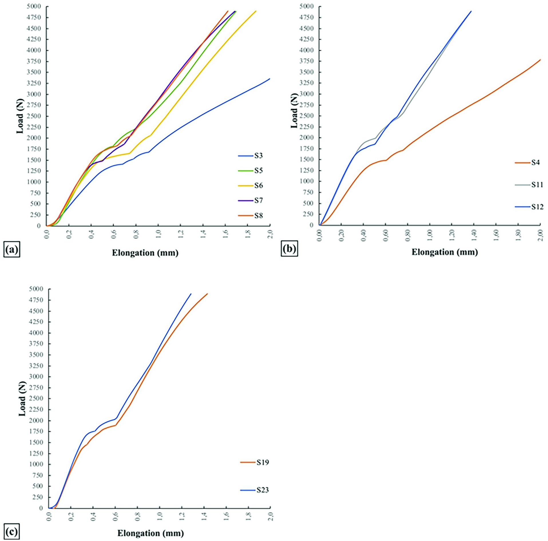
Load elongation curves of S3, S4, S5, S6, S7, S8, S11, S12, S19 and S23: (a) S3, S5, S6, S7 and S8, (b) S4, S11 and S12, (c) S19 and S23.
Figure 11(b) shows the effect of same resin types on load elongation of composite tapes reinforced by the same carbon fabrics of 6 layers. In this case too, composite tapes produced with FER had lower modulus and higher elongation for all forces. After 1750 N, elastic modulus decreases to a lower value compared to 0–1500 N interval. In other two resin types (MER, HER), both load elongation curves followed the same trace up to 1750 N. At 500 N, the elongation of the tapes with both resins were found around 0.10 mm which is lower than that of 4 layers composite tapes. As a result, type of resin except FER one, did not have a significant effect on load elongation curve of composite tapes up to 1500 N force.
Additionally, 300 g/m² UD fabrics of 3 layers were used in a composite structure with two different epoxy resins (MER, MGER). Figure 11(c) shows load elongation curves of two composite tapes. One of the resins was at medium hardness (MER) and the other (MGER) was harder than MER. Both composite tapes followed the same load elongation curve up 1000 N and then MER resin showed slightly lower elastic modulus and higher elongation. At 500 N, elongation in both composite tapes were around 0.14 mm.
These three load elongation curve groups indicate that at forces up to 1000–1500 N, all the epoxy resin groups except FER type showed very close load elongation curves and elastic modulus and can be used to produce composite rapier tape with a proper number of carbon fabric layer and carbon fabric type reinforcement satisfying minimum elongation up to 1000 N force.
Carbon composite tapes are wrapped around a gear or disc type of wheel with a diameter of 300–400 mm. Therefore, bending behavior is also important. The above defined 23 composite samples were also subjected to 3-points bending tests. Results are presented as bending force-bending height curves in Figures 12 to 14.

Bending force and bending height curves of S1, S2, S3, S4, S6, S8, S9, S10, S13, S15, S17 and S18: (a) S1, S2, S3 and S4, (b) S6 and S10, (c) S8 and S9, (d) S13, S15, S17 and S18.

Bending force and bending height curves of S6, S13, S14, S15, S16, S17, S19, S20, S21 and S22: (a) S19, S20 and S21, (b) S13 and S14, (c) S16 and S17, (d) S6, S15 and S22.
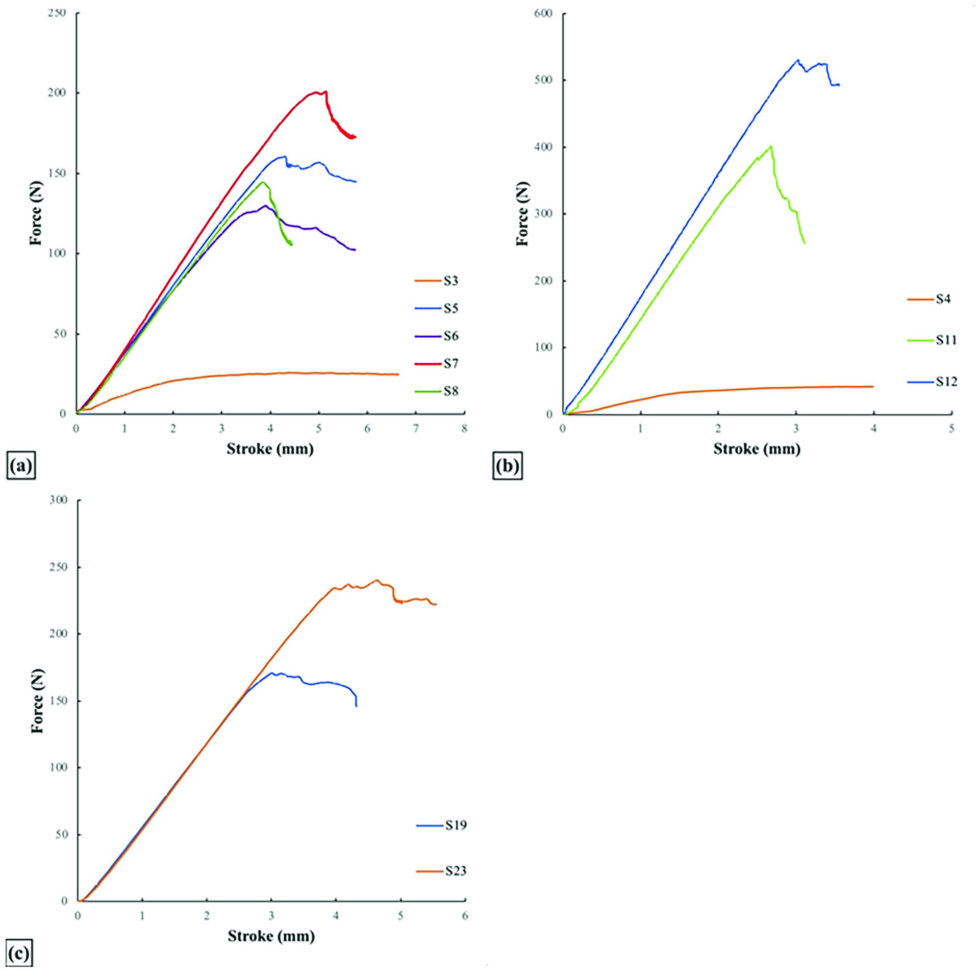
Bending force and bending height curves of S3, S4, S5, S6, S7, S8, S11, S12, S19 and S23: (a) S3, S5, S6, S7 and S8, (b) S4, S11 and S12, (c) S19 and S23.
Flexural properties
Effect of number of fabric layer on bending behavior of composite rapier type
Figure 12(a) shows bending force with respect to bending height (stroke) of carbon reinforced composite tapes produced with FER resin and 2, 3, 4, 5 layers of 200 g/m2 plain weave carbon fabric. As seen from the curves, bending force increased almost linearly up to around breaking force (maximum bending force). Fabric layer showed a significant effect on both bending curve (bending modulus), maximum bending force and bending height. Maximum bending height and force were measured 5 mm and 8 N for 2 layers composite tape. Maximum bending forces increased to 20, 22 and 37 N while maximum bending heights were recorded as 2.5, 2.6, and 2.5 mm respectively for 3, 4, 5 layers composites. Very small maximum bending forces were obtained with FER and bending heights were also relatively small and very close to each other.
Figure 12(b) shows bending force with respect to bending height (stroke) of carbon reinforced composite tapes produced with MER and 4, 5 and 6 fabric layers of plain weave. Maximum bending forces were measured 125, 175 and 400 N while maximum bending heights were recorded as 3.5, 2.75 2.75 mm respectively for 4, 5, 6 layers composites. Compared to FER especially maximum bending forces increased significantly around five times for 4 and 5 fabric layer composite tapes. Number of fabric layers had an increasing effect on bending force. Bending force increased from 125 to 400 N when fabric layer changed from 4 to 6. This is a significant increase for the design of composite materials. For 5 layers composites, maximum bending height increased compared to that of FER in addition to significant increase in maximum bending force.
Figure 12(c) shows bending force with respect to bending height (stroke) of carbon reinforced composite tapes produced with MER and HER mixed with 50:50% ratio and, reinforced by 4 and 5 fabric layers of plain weave. Maximum bending forces were measured as 165 N and 250 N while maximum bending heights were found as 3.75 mm and 3.5 mm respectively for 4 and 5 layers composites. Compared to MER, especially maximum bending forces increased significantly around 50%. At the same time bending heights increased to 3.75 mm and 3.5 mm from 3.5 mm, 2.75 mm respectively for 4 and 5 layers composite tapes.
Effect of fabric layer on bending properties of UD fabric reinforced composite tapes was investigated by producing composite tapes with MER and 3, 4, 5 and 6 layers 200 g/m2 UD fabrics. Results are seen as four different curves in Figure 12(d). Increasing number of fabric layer increased maximum bending force significantly.23,24 Maximum bending forces were measured as 82, 130, 170 and 260 N while maximum bending heights were found as 4.3, 2.5, 1.9 and 1.9 mm respectively for 3, 4, 5 and 6 layers composites. Comparing maximum bending properties of 4 and 5 layers composites produced with 200 g/m2 UD and 200 g/m2 plain weave fabrics, maximum bending forces were found very close to each other as 125–130 and 175–170 N. But maximum bending heights decreased significantly in the case of UD fabric from 3.5 to 2.5 mm for 4 layers and from 2.75 to 1.9 mm for 5 layers. As a result, bending rigidity increased using UD carbon fabric.
Effect of fabric type and placement on bending behavior of composite rapier type
Composite rapier tapes were produced with four different fabric placements as reinforcement with MER matrix. In the first composite group, three layers 300 g/m2 UD carbon fabrics were placed with 0° orientation in the first placement. In the second placement, the first and third layers of 300 g/m2 UD carbon fabric were put on top of each other with 0° orientation and a plain weave 200 g/m2 carbon fabric was inserted between them. In the third placement, the first and third layers of 300 g/m2 UD carbon fabric were put on top of each other with 0° orientation and a 300 g/m2 UD carbon fabric was inserted with 90°s orientation between them. Figure 13(a) shows bending force and bending height curves for these three composite tapes (S19, S20, S21). There are small differences between the maximum bending forces and maximum bending heights. Maximum bending forces were measured as 170, 172 and 188 N while maximum bending heights were found as 3, 3.3 and 3.3 mm for sample number of 19, 20 and 21 respectively.
Second group composite tapes were produced with 200 g/m2 UD carbon fabric with all three layers oriented with 0° in the first composite. In the second composite, the first and third layers were placed with 0° orientation and the second layer was inserted in between with 90°s orientation. As seen from Figure 13(b), maximum bending force decreased in the second placement due to 90°s orientation of middle layer. Maximum bending forces were measured as 83 N and 59 N while maximum bending heights were found as 4.2 mm and 3.8 mm for sample number of 13, 14 respectively. Maximum bending height also decreased in addition to decrease in maximum bending force.
In the third group of experiments, composite produced with 5 layers of 200 g/m2 carbon fabric reinforcement and MER matrix. In the first composite (S16), the first two and last two layers of 200 g/m2 UD carbon fabrics were placed with 0° orientation and a 200 g/m2 plain weave carbon fabric was inserted between them. The second composite (S17) was the same as the first one, but 200 g/m2 UD carbon fabric was inserted 90°s orientation instead of plain weave fabric. Results are presented in Figure 13(c). Two curves were obtained similar each other. Maximum bending forces were found as 193 and 176 N and maximum bending heights as 2.5 and 2.25 mm. Compared to the second group of composites; maximum bending forces increased significantly due to the higher number of fabric layers. But maximum bending heights decreased to almost a half value. UD fabric is a material characterized by yarn alignment in a single direction. While it exhibits favorable mechanical properties along the fiber axis, the inter-fiber binding strength is insufficient under bending forces, leading to a suboptimal overall synergy of the material. Plain weave fabric placement distributes force more effectively in other directions compared to UD fabric and enhances the maximum bending force. 25
Fourth group of composites were produced with 4 layers carbon fabric reinforcements with MER matrix. Type of carbon fabrics were chosen as 200 g/m2 plain weave (S6), 200 g/m2 UD (S15) and 300 g/m2 UD (S22) carbon fabrics with 0° orientation. Bending force and bending height curves are shown in Figure 13(d). Highest maximum bending force (265 N) and lowest bending height (2.27 mm) were obtained with 300 g/m2 UD carbon fabric. Lowest maximum bending force (126 N) and highest bending height (3.6 mm) were recorded with composite tape containing 200 g/m2 plain weave fabric. Composite tape with 200 g/m2 UD carbon fabric produced its maximum bending force close to 200 g/m2 plain weave fabric composite tape. But maximum bending height (2.5 mm) differed significantly from 200 g/m2 plain weave fabric reinforced composite.
Effect of resin type on bending behavior of composite rapier type
The effect of resin type on bending properties of 200 g/m2 plain weave reinforced 4 layers composite tapes is demonstrated Figure 14(a). Except FER, the bending force-bending height curves of MER, SER, HER and mixed (MER + HER) resins for 4 layers composite tapes were found to be very similar to each other and have linear relationship. Maximum bending force increased as 125, 144, 160 and 200 N with the order of MER, mixed, slow (SER) and HER. Maximum bending heights also increased with the same resin order from MER to HER as 3.5, 4, 4.3 and 5 mm. Increase in both maximum bending force and maximum bending height are desired for the requirements of a composite rapier tape. Changing from MER to HER increased maximum bending force at 60% level and increased maximum bending height at 43% level. Experiments were repeated with 6 layers of 200 g/m2 plain weave fabric with FER, MER and HER resins. Results are seen in Figure 14(b). Very small values of maximum bending force and bending heights were obtained with FER. 380 and 522 N maximum bending forces and 2.5 and 3 mm maximum bending heights were measured with MER and HER composites respectively. In this case too, both maximum bending force and maximum bending height increased from MER to HER usage as is the case with 4 layers composite tapes.
Another experiment was carried out with 3 layers of 300 g/m2 UD carbon fabric with MER and MGER resins. Bending force and bending height curves shown in Figure 14(c). Maximum bending forces were measured 170 and 234 N, and maximum bending height 3 and 4 mm with MER and MGER resins respectively. With this resin change, both maximum bending force and bending height increased and better properties were obtained.
Evaluation of suitability of the produced carbon composites as a rapier tape material
In the literature no research was found specifying the technical parameters of composites suitable for use as rapier tape. For this purpose, load elongation curve and bending force-bending height relation were obtained for a commercial carbon rapier tape for comparison purpose. On the other hand, some technical specifications were found in the web site of a commercial rapier tape producer. Bending strength and bending modulus limits are defined in this reference for the suitability of composites for use as a rapier tape. 5 These limits are ⩾150 N/mm2 for bending strength and ⩾4.5 GPa for bending modulus. Bending strength and bending modulus of all of 23 samples were calculated and presented in Figure 15. Samples 1–4 produced with FER failed to satisfy limit bending strength value. Other composite samples satisfied the limit bending strength and bending modulus values. However, no explanation was given in this reference if these limit values belonged to composite tapes for rapier weft insertion system without guides on the reed.

Maximum bending strength and bending modulus values of all 23 samples.
Figure 16 shows load elongation and bending force-bending height curves of a commercial carbon reinforced rapier tape used in rapier looms without guides on the reed. As seen Figure 16(a) load elongation curve commercial composite tape has high modulus of elasticity. Its elongation was measured as 0.06 mm at 500 N and 0.13 mm at 1000 N force. This is a desired property for a rapier tape for a proper weft transfer in the middle of the shed without problem. This can be taken as a target to reach in developing composite rapier tape. Figure 16(b) shows bending force versus bending deflection relation for the same commercial composite tape. Bending force increased linearly with bending height and suddenly got broken. Maximum bending force was measured 682 N and maximum bending deflection was obtained as 5.4 mm. This can also be taken as a reference parameter for bending behavior of rapier tapes. It must be pointed out that this commercial carbon reinforced tape was used in industry with rapier weft insertion systems without guide elements.
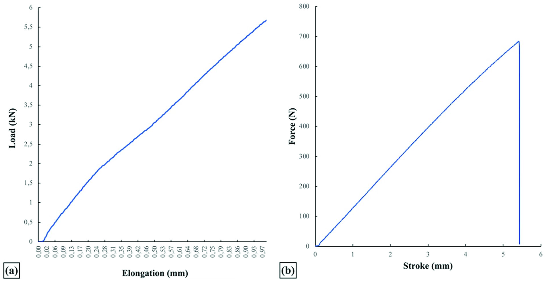
Load elongation and bending force-bending height curves of a commercial carbon reinforced rapier tape: (a) load elongation curve, (b) bending force-bending height curve.
Table 4 shows maximum elongation in the middle of the shed and bending forces when the composite tapes are bent at rapier drive wheel radius of 150 and 200 mm. Bending force at break is also given. Equations (3)–(12) were used in the calculations in the table as was explained above in ‘Motion Analysis of Rapiers’ part. As seen from the table, the smallest maximum elongations were obtained with commercial rapier tape as 0.30 and 0.56 mm when the tape was subjected to maximum force in the middle of the shed during weft transfer. The developed composite tapes elongated maximum 0.58 mm at 600 rpm and 1.03 mm at 800 rpm under the same conditions. Majority of the developed composite samples elongated near to commercial rapier tape. Therefore, the developed composite tapes can be seen acceptable for proper weft transfer at high speeds.
Maximum elongations and bending force of composite rapier tapes.

CRT: commercial rapier tape.
Rapier drive wheels of 300–400 mm diameter are used with commercial weaving machines in industry. Bending moment for 150 and 200 mm radiuses was calculated using equation (10). Then forces required to bend at these radiuses were determined using 3-point test sample length to compare the calculated bending force with the bending breaking force. As seen from the table, bending force for all the samples remained well below the breaking force. This can be seen as a positive result for the developed composite tapes for use as a rapier tape. But the bending breaking force is much higher in the commercial rapier tape. High bending breaking force or bending rigidity might help the rapier tape to move on a straight line without guides and increases its service life. Therefore, the research would focus on increasing bending breaking force together with bending height (deflection) of the composite tapes.
For buckling analysis, three different composite samples (S7, S18 and S23) were prepared in 150 mm × 30 mm dimensions (same as in tensile test) and subjected to compression test with the same velocity as the tensile test. Force increased linearly with the reduction in sample length (minus elongation) until buckling occurred. Forces at which buckling started were 183, 656 and 256 N for S7, S18 and S23 samples respectively. These values were compared with the maximum force in opposite direction (negative values) in Figure 8. As buckling force is inversely proportional to square of material length, 19 rapier tape length subjecting negative forces in Figure 8 should be determined. In rapier weft insertion systems, rapiers are guided outside the shed and enter the shed after moving around 200–250 mm outside the shed. Rapier heads (approximately 250 mm) are of relatively rigid structures and require much higher forces for buckling. Therefore, the rapier tape length inside the shed determines buckling behavior. The rapier tape length of 150 mm inside the shed corresponds to around 600 mm total rapier displacement which corresponds to 90° of loom rotation (0.025 s in Figure 8) according to equation (7). Force affecting the rapier tape at this position is 77 N at 600 rpm and 132 N at 800 rpm. When higher forces affect the rapier, it is either outside the shed or the tape length inside shed is small and requires much higher force for buckling. Hence, buckling force measured by compression test for three different composite materials is much higher than forces affecting the rapier tape to cause buckling. Therefore, buckling phenomenon does not seem to be a significant problem in the rapier tape design.
Conclusion
Carbon reinforced composite laminates were developed to use as rapier tapes in this research by using vacuum assisted resin infusion process. Effect of the type of epoxy resin, type of carbon fabric, number of carbon fabric layers and layer placements on load elongation and bending behavior of composite rapier tapes was investigated. Following results were reached after the analysis of experimental and theoretical works.
- It was found that composite laminates produced with FER did not meet the desired bending and elongation values. Among all the resin types, maximum elongation at 500 N and higher forces was obtained with FER in all fabric layers from 2 to 6 (0.64–0.18 at 500 N). All the composite samples produced with FER failed to satisfy bending strength as the values remained below 150 N/mm2.
- Other resin types can be suitable for satisfying bending strength and minimum elongation conditions depending on fabric type and fabric layer except composite laminates produced with MER and 2 as well as 3 layers of carbon fabrics.
- Experimental results showed minimum rapier tape elongations 0.10 mm and lower at 500N were obtained with 3 and 4 layers 300 gr/m2 UD fabric with MER and MGER, 6 layers plain wave fabric with MER matrix.
- Highest bending force values were obtained 6 layers 200 gr/m2 plain weave fabric as 522 N with HER and 380 N with MER. But bending heights were recorded as 3 mm and 2.5 mm. Other high bending force values were obtained with 4 layers 300 gr/m2 fabrics as 265 N but bending height decreased to 2.3 mm. These values are lower and need to be improved compared to the commercial carbon rapier tape.
- Considering all the experimental work and comparing the elongation and bending behavior results with those of commercial carbon rapier tape, elongation of the produced composite tapes was found to be close to that of commercial one at 500 N for both 600 rpm and 800 rpm running speeds. However, both bending force and bending height should be increased with further research to get closer to those of commercial carbon rapier tape. Research is in progress on these points.
- Dynamic motion analysis of rapier tape enabled the calculation of forces affecting the rapier. In this way, rapier tape elongations and buckling of rapier tapes were determined more realistically. It was found that static and dynamic analysis produced the same maximum force during weft transfer in the middle of the shed because of the characteristics of simple harmonic motion. Maximum force affecting to the rapier tape will have different characteristics with different rapier motion curves. Dynamic motion analysis will be a useful tool to calculate the maximum dynamic force affecting the rapier tape and loom main shaft angle at which it occurs.
- Further to this research, cyclic tests and abrasion of the rapier tapes will be studied to complete the research and give decision on the industrial use of the developed composite laminates as a rapier tape.
Footnotes
Acknowledgements
Authors thank Bursa Uludag University (BAP Department) for supporting this research. Authors also appreciate and thank the valuable contributions of Coats Türkiye company for performing 3-point bending tests.
Declaration of Conflicting interests
The author(s) declared no potential conflicts of interest with respect to the research, authorship, and/or publication of this article.
Funding
The author(s) disclosed receipt of the following financial support for the research, authorship, and/or publication of this article: This work was supported by the Scientific Research Project Unit (BAP) of Bursa Uludağ University with the project number FDK-2023-1377.