
Abstract
Among the various methods used to produce metal fibers, one efficient approach involves processing metal staple fibers (type 1.4113) through a steel wool or planing process. In this method, thick metal wire is pulled through a toothed profiled die to create thin, sharp-edged, and flexible wire shavings. A process chain for spinning such planed metal staple fibers into metal spun yarns, including stretch breaking, drawing, flyer and ring spinning, has already been developed. However, the inherent low elongation and brittle behavior of the material often result in fiber damage during the multiple drawing stages, leading to the formation of short fibers and significant dust in the products. To address these challenges, a new single-stage short staple spinning process has been developed to minimize fiber damage and enable the flexible production of high-performance 100% metal staple spun yarn. The spinning module incorporates a delivery, non-crimping, twisting, and winding units, all of which are modularly designed, manufactured, and driven by individual servo motors. Following the commissioning of the spinning module, uniform and reproducible metal-spun yarn with defined properties and scalable yarn counts (1000–2500 tex) was produced and thoroughly characterized to understand the potential of metal-spun yarn. This study presents the potential of the new spinning process to revolutionize metal fiber production, providing a reliable and high quality solution for demanding industrial applications such as automotive brake pads, high-efficiency burners, electromagnetic shielding, heat pipes, cut-resistant gloves, etc.
Keywords
Introduction
Metal fibers, classified as synthetic fibers, include metal filament, cut metal fibers, steel wool, and metal wire, and possess high strength, ductility, temperature resistance, thermal and electrical conductivity, formability, and recyclability. 1 There are various manufacturing methods for the production of metal fibers. The metal foil process involves a cutter pressed against a rotating thin metal strip to produce staple fibers up to 100 µm thick (Figure 1). The melt spinning process heats a metal bar (1) with induction heating assembly (20) to form molten metal, which meets a spinning disk (31) to produce fibers through rapid solidification (Figure 2). The bundle drawing process involves bundling multiple stainless steel wires (1), drawing them to desired diameters, and dissolving the matrix material (2) to yield continuous metal filament yarn (3) as illustrated in Figure 3.

Metal foiling. 2

Melt spinning process. 3
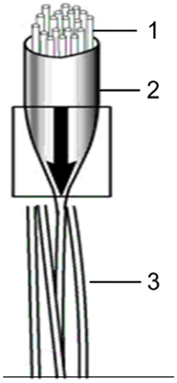
Bundle drawing. 4
Despite these established methods, they remain cost-intensive, highlighting the need for low-cost, high-performance production techniques.5 –9 Metal staple fibers, particularly from thick metal wires, present a cost-effective alternative. German manufacturer Deutsches Metallfaserwerk Dr. Schwabbauer GmbH & Co. KG (STAX) produces such fibers from materials like stainless steel, copper, brass, and aluminum. 10 In the production of planed metal fibers, thick metal wires with diameters ranging from 1 to 5 mm are continuously guided along serrated knives on specialized steel wool machines, where fibers are peeled or planed off. These fibers, known as “metal spun fibers” or “steel wool,” are then bundled and conveyed to rollers in the form of metal staple fiber slivers.10,11 The process allows for a wide range of fineness with adjustable cross-sectional dimensions, achieved by varying the serration of the knives, cutting angle, machine speed, and other parameters. As a result, a variety of metal fibers can be produced, with average lengths ranging from 20 to 800 mm and diameters from 30 to 90 μm. These fibers are available in quasi-continuous forms or milled as short fibers for various applications, categorized by diameter grades as described in Table 1.
Steel wool fiber thickness. 12

Metal fibers have diverse applications across multiple industries. Coarse fibers (>90 µm) are used in cleaning cookware, polishing surfaces, and producing friction linings, while medium-fine to coarse fibers (60–90 µm) are utilized in metal nonwovens. 10 Metal fibers also find use in filtration, heat resistance, composite applications, static protection, electromagnetic shielding, cut-resistant gloves, heat pipes, sound absorption, packing, and gaskets.13 –16 Additionally, they are blended with natural and man-made fibers to enhance product functionality.17 –21 The fine metal staple fibers with a cross-sectional dimension of up to 90 µm exhibit a textile fiber character that is suitable for metal staple fiber yarn production. However, processing fine metal staple fibers into yarns is challenging due to a lack of suitable manufacturing technologies. The abrasive nature of these fibers necessitates wear-resistant drafting systems and guiding elements.
To overcome this, the Institute of Textile Machinery and High-Performance Textile Technology (ITM) at Dresden University of Technology developed a process chain involving stretch-breaking, drawing, flyer, and ring spinning for 100% metal staple fibers.11,22 However, drafting irregularities due to wide fiber length distributions complicated the production of high-quality yarns. A stretch-breaking process was introduced to standardize fiber lengths, facilitating their processing with short staple spinning technology. Despite these advancements, issues such as fiber shortening and drafting irregularities existed, affecting the mechanical properties and generating dust during subsequent processing stages. To address the issue, ITM and the STAX have further developed an efficient, cost-effective, and flexible single-stage spinning process directly from 100% planed metal fiber slivers within a collaborative research project, 23 which has been describes in this paper. This new spinning module, featuring non-crimping, twisting, and winding units driven by advanced software and control technology, enables the production of uniform metal-spun yarns. This innovative approach has been successfully tested with various parameters, resulting in high-performance yarns suitable for technical applications. The study shows the potential of this new process to develop 100% metal spun yarns that provide reliable and high quality solutions for industrial applications.
Materials
The experiment utilized stainless steel planed staple fibers (type 1.4113) delivered by STAX. The 100% metal staple crimped fibers were produced by pressing a blade against a round metal wire (diameter 3.1 mm) in a steel wool machine. The most significant fiber properties as listed in Table 2.
Properties of planed stainless steel fibers. 23

According to Figure 4, the surface of the planed metal staple fiber exhibited a rough and grooved structure in both the longitudinal and cross-sectional directions, resulting in the formation of sharp edges. The geometrical cross-section was not round but rather irregular, taking the form of triangular, trapezoidal, kidney-shaped, and other shapes, contributing to a high deviation in fiber fineness.

Longitudinal and cross-sectional microscopic images of metal fibers (1.4113): (a) longitudinal view of metal fibers (zoom factor: 50), (b) cross-sectional view (zoom factor: 50), and (c) cross-sectional view (zoom factor: 200).
The length distribution of the metal fiber was determined according to the norm DIN 53808-1: 2003 using a single fiber measuring method, which considered 50 fiber samples. Figure 5 illustrated the fiber length distribution, indicating that long metal staple fibers, with a length between 100 and 800 mm, could be produced at the steel wool machine. These long fibers should be retained in the yarn structures to achieve high mechanical properties. The mean

Fiber length distribution of planed metal staple fiber.
Concept and implementation of spinning process of 100% metal spun yarn
The objective of this study was to investigate the feasibility of a single process step from planed stainless steel staple fibers to high-performance and low-cost staple fiber yarns suitable for technical applications. A single-stage concept involved a steel wool machine and a flexible spinning module, which incorporated a non-crimping unit, a twisting device, and a winding unit. As illustrated in Figure 6, thick metal wires (2) were peeled off or planed by pressing with a blade (3) against the metal wire package to produce metal staple fiber sliver (4) on a stainless steel wool machine (1). The produced staple fibers with strong crimp properties were guided to a non-crimping unit (5) of a spinning module with a minimum draft to straighten the fibers without any plastic deformation. Afterward, the non-crimped metal fiber sliver (6) was further guided through flyer top (7), flyer legs (9), and wound on a bobbin (10). Each rotation of the flyer or flyer legs (9) imparted one twist to the metal sliver (6) to develop metal spun yarn (11). The flyer rotated at a constant speed, whereas the bobbin (10) rotated quicker than the flyer, and its speed was adjusted in relation to the increased diameter. The winding speed was the difference between the circumferential speed of the flyer (9) and the bobbin (10), corresponding to the delivery speed of the non-crimping unit. The machine and process parameters could be set by different servomotors (M1–M6) in a modular manner, depending on the fineness of the metal fiber sliver, yarn count, yarn twist, and so on. The drive system comprised of six servomotors (motors 1–3: drafting rollers of the non-crimping unit (5); motor 4: flyer (9); motor 5: spindle or bobbin (10); and motor 6: lifting motion). The angular speeds of the motors were independent of each other and variable. The non-crimping unit was equipped with motors 1–3, which rotated in the following order of speeds: Motor 1 < Motor 2 < Motor 3. Motors 4 and 5 were essential for twisting and winding the yarn, with the synchronized speed ratio between the bobbin (10) and the flyer (9), respectively.

Schematic diagram of single-stage spinning process of 100% metal spun yarn.
Non-crimping unit to reduce fiber crimp
During the production of planed metal staple fiber at a steel wool machine, the fibers were strongly crimped, which led to process instabilities throughout the spinning process. In order to achieve uniform yarn, a non-crimping unit was designed, constructed, and manufactured in order to reduce the crimp of the fibers (Figure 7). The non-crimping unit operated according to a conventional drafting system, which serves to align the fibers in the production direction. To construct the non-crimping unit, two successive drafting zones consisting of three pairs of rollers, namely the input, middle, and output rollers, were designed. Zone 1, situated between the input and middle rollers, and was designed to ensure an appropriate feed. Zone 2, situated between the middle and delivery rollers, and was designed to eliminate the fiber crimp by applying the minimum amount of draft required for non-crimping of the infeed metal fiber sliver (Figure 7(a)). Additionally, there was a tendency for the smooth metal fibers to slip during processing in the non-crimping unit. To enhance the static friction between the metal fiber sliver and the drafting rollers, the bottom rollers of the non-crimping unit were modified with a high-wear-resistant (surface roughness, average maximum height of the profile, Rz of 20–25 μm according to ISO4287) hard chrome bottom rollers. Rz represents a more moderate view of the roughness extremes compared to the total height of the profile Rt. All the bottom rollers were directly driven by individual servomotors. The top rollers, which were equipped with a spring-loaded arm, serve to further clamp the metal fiber sliver in zones 1 and 2.

Concept of: (a) non-crimping unit and (b) twisting, lifting, and winding device of the spinning module.
Twisting device for metal staple yarn
The concept of twisting device is based on flyer spinning technology. As illustrated in Figure 7(b), the non-crimped fiber sliver was twisting through the rotation of flyer driven by servo motor M4. Each rotation of the flyer imparted one real twist to the fiber sliver. In consideration of the stiffness of stainless steel staple fibers, a flyer including an abrasion-resistant flyer top was designed. The fiber sliver ran through the flyer top, the hollow flyer leg, and finally was wound on the bobbin after passing several times around the pressing arm located at the flyer leg.
Lifting and winding device
The lifting and winding devices are designed for executing a defined cylindrical parallel winding on a precision bobbin was developed based on flyer spinning principle. In the lifting mechanism, Motor 5 was connected to the driving shaft and bobbin via a pair of gears (Z1, Z2, and Z3) for the rotation of the bobbin (Figure 7(b)). The gear Z3 was directly connected to Motor 5, whereas Z2 was connected to the driving shaft, transmitting the rotational speed of the motor to the bobbin. In addition, the gear Z1, mounted on the driving shaft, moved up and down during the movement of the bobbin rail. However, Motor 5 did not move vertically up and down during the formation of the bobbin; rather, it was fixed to the machine frame to avoid any unbalanced lifting motion. Furthermore, the bobbin rail glided through the linear guiding elements to ensure stable lifting movement driven through Motor 6. A position control sensor was implemented to adjust the lifting movement after each stroke. In order to achieve a defined coil height, the bobbin rail was moved up and down continuously in order to wind yarn on the bobbin. During the spinning process, the speed of the bobbin decreased after each layer as the bobbin diameter increased. As the diameter of the packages increased with each wound layer, accompanied by a corresponding increase in the length of roving wound per coil, it was necessary to reduce the speed of movement of the bobbin rail by a small amount after each completed layer.
Integration of the non-crimping, the twisting, lifting and winding units to the spinning module
All the units described in Sections 3.1, 3.2, and 3.3 were manufactured, procured and integrated to construct the flexible spinning module for single-stage spinning of stainless steel staple fibers into spun yarn (Figure 8). The newly developed spinning module had a challenge due to the necessity of combining the mathematical relationships among different sets of process parameters with software, individual drive modules, and control technology in a single process step. To address this challenge, ITM developed mathematical algorithms to synchronize the complete spinning process. Baumüller provided the software and driving technology to implement a B-Maxx PCC-04 controller, which included a touch panel, a rectifier, three dual-axis servo regulators, and six DSD2 servo motor drives designed with precise functionality during acceleration. The system is equipped with start-stop operation, and an application-optimized software solution with an intuitive and easy-to-use interface. This enabled flexible and efficient production thanks to an easy-to-use user interface and recipe handling with simple parameter entry. 24 The input machine parameters, including the silver count, desired yarn count, yarn length to be wound, draft, ring rail position, yarn twist, coil height (i.e. distances between the coil layers), and bobbin diameter. From the operating panel, the actual values of various machine parameters are displayed, including production speed, production time, remaining production time, produced yarn length, total draft, actual ring rail position, bobbin speed, and so on.

Newly developed spinning module.
Moreover, the machine monitored the production process and automatically shut down when the desired quantity of yarn was produced. However, if a machine operator opened the work area, the STO (Safe Torque Off) safety function was activated to shut down the drives quickly in a controlled manner. The advantages of the developed spinning module are summarized below:
The machine is equipped with individual drives for the non-crimping unit, spindle or bobbin, flyer, and the lifting units.
The direction of rotation of the flyer can be selected for the production of the yarns, taking into account the S and Z yarn twist.
The package construction can be flexibly modified by changing the coil height and yarn diameter.
The master speed can be flexibly selected, either as the flyer speed or the delivery speed.
Testing and trails at the developed spinning module
At the developed spinning module, investigations were conducted for developing 100% metal spun yarn with a wide variety of yarn counts by considering various process parameters in Table 3.
Process parameters for the spinning module.

The draft was set according to the input sliver count and the desired yarn count only to straighten the fiber, that is, without any material elongation, in order to reduce fiber breakages in the drafting zone. To set the twist value with respect to yarn count, standard Koechlin’s equations were applied:

where, Ttex: the number of twist in twist/meter; αe: Twist coefficient in English count system; Tex: direct yarn count system in g/km.
Figure 9(a) illustrates a spool of stainless steel spun yarn with a yarn count of 1000 tex and 107 TPM. The yarn structure of the metal spun yarns produced was optically examined using a high-resolution reflected light microscope (Zeiss AxioImager.M1m). As shown in Figure 9(b), the microscopic longitudinal views of the yarns (yarn structure) for different yarn counts and yarn twists are displayed. It was observed that the yarns with higher yarn twist were compact and had lower yarn hairiness. This high yarn hairiness could negatively affect the further processing of the yarn on the fabric formation machines.

(a) Bobbin made of 100% metal spun yarn and (b) its microscopic structure with different yarn counts and yarn twists: (a) metal spun yarn and (b) microscopic images of metal spun yarns.
Due to the large diameter of metal staple fibers (on average 56 µm) and their high density (7.7 g/cm³), as well as the limitation of producing a minimum input sliver count, yarn finer than 1000 tex could not be realized. For spinning finer yarns (i.e. <1000 tex), the fineness of the input sliver needed to be adjusted accordingly. Through a series of trials, the optimal machine and process parameters were identified for each yarn count, flyer, and production speed.
To evaluate the suitability of the newly developed stainless steel staple fiber yarns (with a fineness of 2000 tex and a yarn twist of 80 TPM), a plain weave fabric structure was successfully produced, achieving a warp and weft density of 3 threads/cm on a handloom setup at ITM. The warp yarns were stretched parallel, with consistent warp density, in a single plane. The weft sheds were formed using an angled stainless steel tube, which was alternately threaded over and under the warp yarns. Through this tube, the weft yarn was then pulled, preventing friction between the warp and weft yarns while simultaneously pressing the previous weft yarns against the fabric edge with the stainless steel tube. This process repeats with each alternating shed formation until the desired fabric length achieved. However, investigations based on weaving technology showed that the hairiness of metal spun yarns was still too high for further processing on weaving machines and should be significantly reduced with an appropriate solution in future research work.
Characterizations techniques
The produced yarn was characterized according to the norm as follows (Table 4):
Testing plan.

Results and discussion
Tensile properties of 100% metal staple fiber and its resultant spun yarns
The level of utilization of the fiber strength in the yarn has a decisive influence on the resulting yarns. The higher the fiber strength and the higher the level of its utilization, the higher the yarn strength. The mechanical characterization of the fibers was carried out by means of single fiber tensile tests in accordance with DIN EN ISO 5079 using the FAVIMAT+ test instrument from Textechno Herbert Stein GmbH & Co. KG. Figure 10 shows tensile stress-strain curves for stainless metal stainless metal staple fibers. Initially, all curves display a linear relationship, indicating elastic deformation with proportional stress and strain. Beyond a certain point, the curves deviate, entering the plastic deformation phase where materials stretch with increasing stress until reaching maximum capacity. Beyond this point, the materials undergo necking and eventually fail, as indicated by the sharp drop in the curves. The average fiber strength and its corresponding elongation were measured to be 971 ± 84 MPa and 1.8 ± 0.33%, respectively. The standard deviation (±84 MPa) indicates some variability in fiber strength. This variability can affect yarn strength, as inconsistencies in fiber cross section and strength can lead to weak points in the yarn. Moreover, metal fibers exhibit limited elongation before failure, indicating that they are relatively brittle. Given that the fiber diameter is considerably smaller than the fiber length in the case of metal staple fibers, deformation can only occur to a limited extent, resulting in immediate mechanical failure upon reaching the maximum tensile stress. The necking of tensile-loaded metal fibers can be attributed to the formation of isolated plastic deformation in the necking area. The rough surface of the metal fibers intensifies this phenomenon. Plastic deformation occurs both along the fiber direction and transversely to it. The extreme irregularities in fiber geometries can be identified as the primary cause of the significant variation in fiber properties, such as tensile strength and breaking elongation.
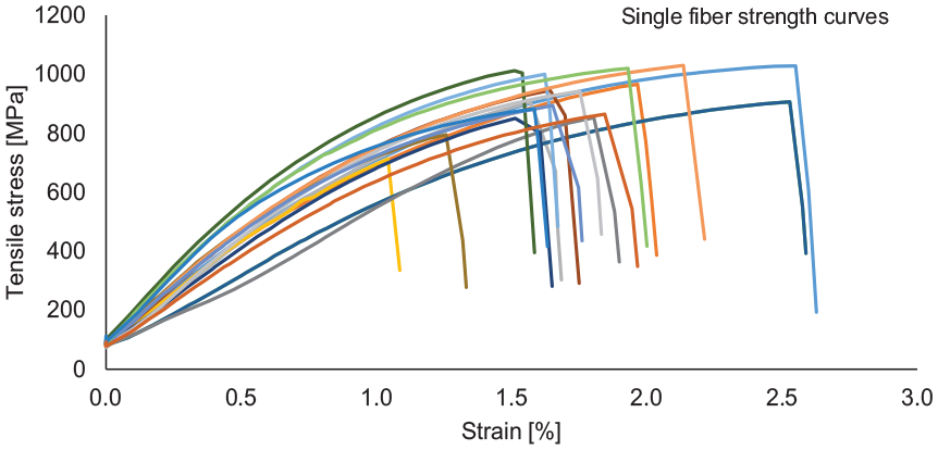
Stress-strain behavior of stainless steel (1.4113) staple fiber.
The stress-strain behavior of the stainless steel spun fiber yarns was determined on the Zwick Z100 tensile testing machine in accordance with DIN EN ISO 2062. Figure 11 exemplifies the stress-strain behavior of a stainless steel spun fiber yarn (1000 tex, 107 TPM). The yarn initially exhibits elastic behavior, followed by nonlinear regions indicating plastic deformation, but it shows significant variation in the stress-strain behavior. The diagram shows the successive failure of individual fibers. The multiple peaks and drops in the curves suggest the progressive failure of fibers under increasing strain, reflecting variations irregularities in fiber geometry, such as variations in diameter, tensile strength, and surface roughness among the fibers. This irregularity leads to inconsistencies in yarn properties, making the yarn more prone to defects and uneven stress distribution. Moreover, the brittle nature (limited elongation) of metal fibers may lead to sudden failure of the yarn under stress. The investigation also indicated that the mechanism of the frictional behavior between fibers with respect to yarn twist needs to be further analyzed. The relationship between the fiber and its resultant yarn properties has to be well understood.
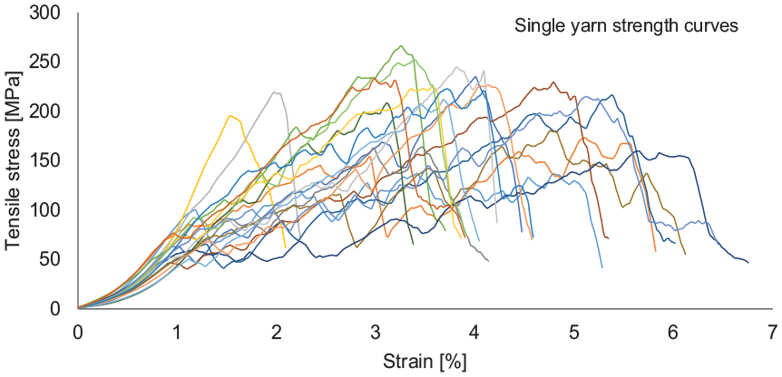
Stress-strain behavior of metal spun yarn (1000 tex, 107 TPM).
The specific yarn strength and corresponding yarn elongations for different yarn counts and yarn twists were determined and are shown in Figure 12. The yarn tenacity for different yarn counts varied between 157 ± 14 MPa (2500 tex) and 213 ± 34 MPa (1000 tex), while the elongation values ranged from 3.0 ± 0.3% to 5.4 ± 1.1%. In general, the specific yarn strength and the corresponding elongation decreased from finer to coarser yarn counts. In comparison to the fiber strength, only about 22% of the yarn strength could be achieved with a yarn count of 1000 tex and a yarn twist of 107 TPM. These properties of metal fiber yarns are sufficient to be processed smoothly in the subsequent fabric formation process.

Influence of yarn counts on yarn strength and yarn elongation of metal spun yarn.
Yarn evenness
The evenness of yarn, which refers to the uniformity of the yarn’s thickness and mass per unit length, is a critical quality parameter that influences the appearance, performance, and processing of the yarn in textile applications. The evenness of the stainless steel staple fiber yarn was not determined capacitive according to the state of the art due to its electrical conductivity, but was determined by weighing at least 20 yarn samples with test lengths of 1 m each according to DIN EN ISO 2060. Figure 13 shows that the evenness (CV-1 m %) of the yarn generally decreased from 3.61% to 3.22% with increasing yarn count between 1000 and 2500 tex. The observed decrease in CV-1 m % as the yarn count increased suggests that thicker yarns (higher tex values) tend to be more even. This could be because thicker yarns incorporate more fibers, averaging out individual fiber irregularities. The evenness of the yarn could be influenced by the evenness of the input sliver, the compactness of the yarn, the fiber geometry, the twist values and their variation.

Influence of yarn counts on yarn evenness of metal spun yarn.
Yarn twist
To address the sensitivity to shear force and the irregular geometries inherent in metal fibers, a low twist was employed during the production of metal spun yarns to prevent the resulting fiber damage while still ensuring sufficient yarn strength for the subsequent fabric formation process. The yarn twist of the manufactured stainless steel staple fiber yarns was determined by the untwisting method using the D 312 tester from Zweigle Textilmaschinen GmbH, according to DIN EN ISO 2061. The comparison between nominal and actual twist for different yarn counts is shown in Figure 14. The investigation results indicated that the set twist and the actual measured twist were comparable across different yarn counts. However, finer yarns (1000 and 1500 tex) exhibited a higher standard deviation in the actual twist compared to coarser yarns. Coarser yarns (e.g. 2500 tex) exhibited lower standard deviation in actual twist, suggesting more consistent twist application. This consistency helps in achieving better yarn evenness by ensuring uniform fiber distribution and tension throughout the yarn length.

Actual yarn twist for different yarn counts of metal spun yarn.
Yarn diameter and hairiness
Yarn diameter and hairiness have a significant influence on the further processability of the metal spun yarn with respect to yarn guide elements and dust formation in the fabric forming process. The yarn diameter and hairiness of the conductive stainless steel staple fiber yarns were determined optically using the CTT-YPT instrument from Lawson-Hemphill Inc. The instrument had a modular design and was equipped with a CCD camera unit (12 mm lens diameter) and a light source. The camera contains 2048 light-receiving elements, referred to as pixels. As the yarn passes through, light is projected onto one side of the yarn and is either blocked by the yarn or received by a pixel in the CCD array. 25 While the yarn moved past the camera at an inspection speed of 20 m/min, 100 images per cm were recorded (Figure 15).

Hairiness module of the measuring device CTT-YPT of Lawson-Hemphill Inc.
The yarn diameter with and without protruding fibers was measured optically with respect to different yarn counts and yarn twists. The core yarn diameter, that is, without protruding fibers, varied from 2.3 mm (1000 tex) to 3.2 mm (2500 tex) with respect to yarn counts (Figure 16).
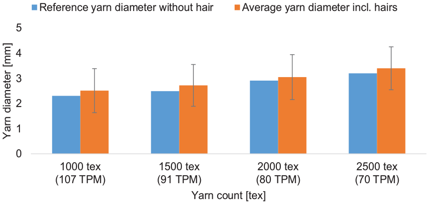
Average yarn diameter of metal spun yarn for different yarn counts.
In addition, the number of protruding fiber ends per meter of yarn (hair length: 1–6 mm) was determined as a function of yarn diameter considering different yarn counts. As shown in Figure 17, it was observed that yarn hairiness was primarily caused by protruding fibers of 2–4 mm, which influenced the yarn structure and the subsequent fabric formation process. The reasons for the higher hairiness of the metal fiber yarn are due to the high stiffness and uneven fiber geometries when the yarn is twisted, the metal fibers either break or the metal fibers, especially the edge fibers, are not integrated into the yarn structure. Higher hairiness contributes to high friction between the fiber and the fiber feed elements, resulting in dust generation during the fabric forming process as protruding fibers break off, creating debris.

Yarn hairiness of metal spun yarns with respect to the reference diameter (RD) for different yarn counts.
Unwinding behavior of 100% steel spun fiber yarns
To explore the yarn unwinding behavior of metal yarn during subsequent processes, such as weaving, an unwinding measurement setup was utilized. The unwinding behavior of the yarn was determined based on the measured yarn tension forces during the unwinding of the yarn from the yarn package at an unwinding speed of 5–15 m/min for different yarn counts (Figure 18(a)). A force sensor from Hans Schmidt & Co GmbH was employed, connected to the National Instruments (NI) LabView data acquisition program, to measure the yarn tension during yarn unwinding. Figure 18(b) shows the yarn unwinding behavior of the 2000 tex yarn sample at different unwinding speeds (5–15 m/min). For instance, at a take-up speed of 15 m/min, the average yarn tension measured approximately 180 cN, whereas the average tension derived from the force-elongation behavior was approximately 6000 cN. This indicates that further processing of this yarn into textile fabrics is possible at much higher running speeds. However, due to the abrasive effect of the metal yarns, especially on the guide and measuring rollers of the force sensor, the unwinding behavior was investigated up to 15 m/min.

(a) Test set up for the unwinding behavior of the metal spun yarn and (b) yarn unwinding behavior for 2000 tex with take-off speeds 5–15 m/min.
Bending stiffness of woven fabric from 100% steel spun fiber yarns
The flexural stiffness of the developed plain weave fabric (Figure 19) was determined using the cantilever principle along the sample width in accordance with DIN 53362 using the ACPM 200P testing device from Cetex GmbH (Figure 20). This device determined the bending at several measuring points along the sample width simultaneously. The bending stiffnesses with respect to the 0 position of the sample width for the warp and weft directions of the fabric were 154.78 and 709.90 mN*cm, respectively, while the bending stiffness of a 100% cotton reference fabric was 1.48 mN*cm. However, the 100% metal spun fabric structures were significantly stiffer than conventional fabrics, but still exhibited some drapability compared to rigid metal mesh or metal sheets.

Plain woven fabric sample.
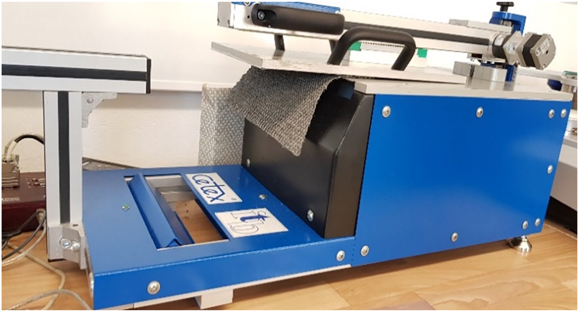
Measurement of bending stiffness of fabric.
Conclusion and outlook
This study highlights the need for innovative manufacturing technologies to process fine metal staple fibers into high-quality yarns. The development of a single-stage spinning process represents a significant advancement, addressing previous challenges and paving the way for the efficient production of metal-spun yarns for a wide range of applications. A single-stage process chain has been developed to process 100% metal planed staple fibers, incorporating non-crimping, twisting, and winding units. This advancement not only addresses the current production challenges but also opens up new possibilities for the application of metal fibers in various technical fields, enhancing both performance and cost-effectiveness. High-performance and cost-effective stainless steel yarns with different finenesses (1000–2500 tex) and twists were developed, showing that various process parameters affect the quality of 100% metal spun yarns. The metal fiber spun yarn exhibited a maximum tensile strength of 213 MPa and elongation of 5.4%. The fabric structure of the developed stainless steel staple fiber yarn, made entirely from stainless steel staple fibers, also demonstrated great potential for technical applications such as cars, construction, sports equipment, plants, and heating.
Footnotes
Acknowledgements
The authors would like to thanks Baumüller GmbH for the implementation of the driving and software technology of the newly developed spinning module.
Declaration of conflicting interests
The author(s) declared no potential conflicts of interest with respect to the research, authorship, and/or publication of this article.
Funding
The author(s) disclosed receipt of the following financial support for the research, authorship, and/or publication of this article: The project is supported by the ‘Zentrales Innovationsprogramm Mittelstand (ZIM) ZF4008324CJ8’ of the German Federal Ministry of Economics Affairs and Energy on the basis of a resolution of the German Bundestag.