
Abstract
Ultra-high molecular weight polyethylene (UHMWPE) and its decalin suspension were subjected to several industrial processes including swelling, dissolving, spinning, drying, and multi-stage high-ratio hot drawing to fabricate UHMWPE fibers (UPE fibers). The morphologies and architectures of the UPE fibers at different drawing stages were characterized by polarizing optical microscope (POM), scanning electron microscope (SEM) and atomic force microscopy (AFM). The aggregation structure evolution of UHMWPE macromolecules during the high-ratio hot-drawing process was studied by differential scanning calorimeter (DSC), wide-angle X-ray diffraction (WAXD), small angle X-ray scattering (SAXS) and other testing methods. The experimental results demonstrated that the UHMWPE/decalin spinning suspension was extruded from the spinneret hole to form a fine spinning flow, followed by the formation of the transitional-state fibers at different processing stages, and finally the ready-made fibers. The total drafting ratio of the UPE fibers after fabrication reached more than 600 times. The diameter of the single UPE filament was reduced to 5.66 μm with elevated drawing ratios. The crystal structure of the prepared UPE fibers was progressively improved, and the folding-chain crystals of fibers gradually transformed into extended-chain crystals. The mechanical properties of the UPE fibers were significantly improved. The fracture strength of the as-spun UPE fibers reaches 48.1 cN/dtex, which endows the fibers with specific characteristics such as ultra-fine denier and ultra-high strength.
Keywords
Introduction
Ultra-high molecular weight polyethylene (UHMWPE) fiber (UPE fiber) has the highest specific strength and specific modulus among all known fiber materials worldwide. 1 It has excellent properties such as light weight, good chemical stability, wear resistance, bending resistance, fatigue resistance, and cutting resistance.2–4 The UPE fiber is widely used in national defense and military industry, 5 aerospace,6,7 safety protection,8–10 ocean transportation,11,12 bioengineering,13–16 and other fields, which indicates the indispensable role that UPE fiber plays in human life and social development.
UHMWPE has a simple molecular structure consisting of barely C-C chain which is linear without large side groups or functional groups. It has characteristics of a small molecular cross-section and high regularity, which conforms to the polymer model with high strength and high modulus features. Theoretically, high-strength and high-modulus UPE fiber can be prepared. 17 According to the literature, the theoretical ultimate strength of the fiber can reach up to 7.2 GPa, and the theoretical maximum modulus is 264 GPa. 18 The fracture process of polyethylene has been thought to be controlled by molecular chain fracture mechanism and intermolecular chain slip mechanism. Theoretical estimation of the ultimate tensile strength of polyethylene ranges from 3.7 to 19 GPa. The higher theoretically estimated value of 19 GPa was considered controlled by the molecular chain fracture mechanism, whereas the lower value of 3.7 GPa is based on the hypothesis of the chain slippage fracture mechanism. 19 There have been numerous studies and reports on the polyethylene fracture mechanism.20,21 It is believed that the actual strength of polyethylene strongly depends on its molecular weight and distribution, morphology, molecular orientation, and test conditions. According to the research and analysis of the actual strength of polyethylene fiber, reducing chain slippage and increasing the number of binding molecules is an effective way to improve the fiber strength, while increasing the molecular weight is the basis and prerequisite for reducing chain slippage and increasing the number of binding molecules. Smith et al. 22 studied the impact of polymer molecular weight on fiber strength. It turns out that there is a strong molecular weight dependence of polyethylene strength at constant modulus. A high molecular weight is desired to fabricate polyethylene fibers with high strength. However, there are studies indicating that excessive entanglement points are not conducive to polymer spinning. 23 Reducing the concentration and molecular weight of the polymer is beneficial for reducing the number of entanglement points of the macromolecules, which is good for improving the stretching performance of the polymer. However, a certain limitation on the lowest number of polymer entanglements should be proposed to maintain the connection of the entanglement network, thereby increasing the polymer drawing ratio and the fiber strength. 24 Wang et al. 25 studied the solution concentration impact of UHMWPE/paraffin oil spinning solution on the fiber structure changes during the drawing process. The results demonstrated that the UPE gel fibers with low concentration in free relaxation state tend to shrink than those with high concentration. What’s more, in the subsequent drawing process, a lower concentration is in favor of the transformation of the extended chain from the entangled chain and the improvement of the mechanical properties of the fibers. The high concentration is adverse to the formation of fibers with perfect structure and high mechanical properties, which is consistent with the research results of An et al. 26 Therefore, it is an effective way to improve UPE fibers’ strength by choosing an appropriate concentration of UHMWPE spinning solution and controlling the number of polymer entanglements. Besides, process parameters employed in the preparation process of UPE fibers play an essential role, which has raised tremendous interest among researchers from both academic and industrial fields.
The preparation methods of UPE fibers are mostly solution gel spinning methods, which could be further subdivided into wet-spinning process and dry-spinning process. The wet-spinning process27,28 mainly exploits non-volatile organic solvents, such as white oil and paraffin oil, to obtain high-strength and high-modulus UPE fibers through various processes, including dissolution, spinning, curing, extraction, drying, multi-stage drawing, and other processes. The dry-spinning process29,30 mainly uses volatile organic solvents, such as decalin, to obtain high-strength and high-modulus UPE fibers through dissolution, spinning, curing, drying, multi-stage drawing, 31 and other processes. Further classification of the dry-spinning processes primarily consists of wind-blowing curing dry spinning and water-bath curing dry spinning, according to the different fiber curing methods. The above-mentioned three spinning processes are depicted in Figure 1.

Schematic illustration of UPE fiber processing routes: (a) dry spinning by air cooling, (b) dry spinning by water cooling, and (c) wet spinning by water cooling.
As shown in Figure 1(a), during the cool-air-assisted dry spinning process, the spinning solution containing volatile organic solvent was extruded from the spinneret nozzle to form a spinning fine flow. The spinning flow was cooled down and solidified by the air, accompanied by a solvent flash evaporation. 32 Meanwhile, a high ratio drawing force on the spinneret nozzle was applied to the spinning flow to ensure the disentanglement of polyethylene macromolecular chains and the prevention of the rewinding of polyethylene macromolecules. The disentanglement of polyethylene macromolecules by applying the draw-down ratio is beneficial for the following hot-drawing process to obtain UHMWPE fibers with excellent physical properties.29,33 A precursor with a low tensile strength of 10 cN/dtex could be prepared, accordingly. At least two further high-ratio hot-drawing processes are needed to obtain UPE fibers with high strength and high modulus.29,33 Water bath assisted dry spinning process is depicted in Figure 1(b). Similarly, a spinning fine flow was formed after the extrusion from the spinneret nozzle. It is distinct that the flow was cooled and solidified with the assistance of the water bath to form the UPE gel fibers.5,30,34 The gels containing volatile organic solvent were dried in the multi-stage drying box to evaporate residual solvent. At this moment, a drawing ratio was applied to the gels to prevent the rewinding of the polyethylene macromolecules. UPE Fibers with high strength and high modulus could be fabricated after further high-ratio hot-drawing processes.
The wet spinning process could be referred to in Figure 1(c). Compared to dry spinning processes employing volatile organic solvents, wet spinning process uses nonvolatile organic solvents instead. The UPE gel fibers formed after the extrusion were disposed into the extractant bath to remove the residual nonvolatile solvent by extraction.26,35 The fibers containing extractant were dried in the drying box to prepare a dry precursor that could form high-strength and high-modulus UPE fibers after multiple drawing processes.
It is worth noting that the technical route for preparing UPE fibers employed in this work is the dry-spinning technique depicted in Figure 1(b). Compared to the dry-spinning technique reported by DSM company, there is no solvent (decalin) flash evaporation after the extrusion of the spinning dope during the technique we proposed. In the patent applied by DSM, 36 a distinct distance between the spinneret and the water-cooling bath was introduced. After the extrusion, a rapid solvent evaporation called the flash evaporation process happened, resulting in a decalin diffusion to the environment. Whereas, in our work, a very close distance within 5 mm between the spinneret and the water bath was precisely controlled. The space enclosed between the spinneret and the water bath was completely covered by the mold wall, forming a confined space where no decalin flash evaporation after the extrusion process happened. No decalin diffusion to the environment was involved in this process. Besides, no extractant was used in this process, during which only a one-way decalin diffusion to the water bath happened.
In summary, the most significant and essential difference between dry spinning processes (Figure 1(a) and (b)) and wet spinning processes (Figure 1(c)) for preparing UPE fibers depends on whether there is an extractant employed in the spinning process. Dry spinning does not require the involvement of the second solvent (extractant), regardless of whether the engaged solvent is directly removed by air cooling or by water cooling and solidifying followed by the heating process. The wet spinning process, on the other hand, is distinct because of the involvement of the new extractant. During this process, the gel bundle is first obtained by water-cooled curing. Then the organic solvent is extracted by another extractant with a low boiling point, and finally, the extractant is removed efficiently to prepare UPE fibers.
The differences in fiber structure and properties obtained through different preparation processes and methods of UPE fibers are still being studied and explored. Henry 37 employed decalin as a solvent in the spinning solution which is extruded from the spinneret hole to obtain UPE gel fibers containing a large amount of solvent. The dry precursor was obtained by volatilizing the solvent in a relaxed state in a vacuum furnace at 50°C, and the structure and properties of the subsequently prepared fibers were studied. An evident flow-induced crystallization with an asymptotic crystallization speed at high Weissenberg numbers was reported. The formation of more straight crystals under drawing was observed. Sun et al. 33 used decalin as solvent to prepare UPE fibers through air-cooled drying and high-ratio hot drawing process, and systematically studied the crystal structure evolution process during the fiber formation process. An optimal draw down ratio was applied on the UHMWPE gels to accelerate the molecular disentanglement, which can be benefit for the following after-drawing process, resulting in UHMWPE fibers with excellent physical properties. Pennings et al. 38 proposed that high-speed and high-rate drawing processes should be involved to prepare UPE fibers. The researchers employed paraffin oil as the solvent and spun the UHMWPE at a very high-speed of 1500 m/min. The as-prepared UHMWPE fibers show good tensile strength of 3.5 GPa. The researchers also studied the shish-kebab structure evolution of UPE fibers at different drawing stages. Tao 39 studied the spinnability of UHMWPE at different concentrations and temperatures. The researchers claimed that solutions with optimal shear viscosities and homogeneity are most spinnable. Comparing to spinning solutions with other concentrations, a higher achievable drawing ratio for the spinning solution with the optimal concentration at each spinning temperature was reported. A better formation of the precursor of shish-kebab entities, birefringence, crystallinity, thermal and tensile properties can be achieved by the as-spun fibers prepared at the optimum concentration and temperature. McDaniel et al. 40 studied the surface morphology change and structural evolution of UPE fibers by means of atomic force microscopy (AFM) and wide-angle X-ray diffraction (WAXD). The AFM results reveal that the distribution of the microfibril width narrows down dramatically with increasing drawing. An average diameter of around 35 nm was reported. WAXD Results show that the scattering signal of the 110, 200, and 020 crystal zones increased as the elevated drawing ratio, reflecting the promoted formation of the crystalline region during the drawing process. Tian 41 exploited small-angle X-ray scattering (SAXS) and WAXD as characterization methods to study the structural evolution of UPE fibers with different drawing ratios at 90°C and 100°C, respectively. An ultra-high total stretching ration of about 2000% was achieved in this work. Experimental results revealed the gradual evolution of fibers from a shish-kebab structure to a fibril structure, according to the SAXS pattern signals depicted in this work.
To further understand the structure evolution of UPE fibers in the dry-spinning process, UPE fiber were prepared by circulating-air solidifying and high-ratio hot-drawing techniques. The properties and structural changes of the as-prepared UPE fibers at different forming stages were studied by using strength tester, POM, SEM, DSC, SAXS, and WAXD. This paper reveals the forming characteristics of UPE fibers under the cool-air-assisted dry-spinning process, which might be profitable to improve the existing UPE fiber industrial production process and conditions.
Experimental methods
Materials
UHMWPE resins (relative molecular weights 5.8 × 10⁶) were purchased from Shanghai Lianle Chemical Technology Co., Ltd. Decalin (purity ⩾98%) was purchased from Evonik Company.
Facilities
Twin-screw extruder (diameter Φ36, length to diameter ratio 50) was purchased from Nanjing KY Chemical Machinery Co., Ltd.
The geometry of the spinneret is cylinder-shaped with a diameter of 0.75 mm. It has70 holes The L/D of the screw we used is 6.
The length of the hot drawing hot box is 8 m and the wire feeding speed is 1.2 m/min.
Fiber preparation
The whole fiber preparation process could be divided into two steps, including fore-spinning process and back-spinning process. The fore-spinning mainly consists of swelling, twin screw dissolution, nozzle drawing, curing, dry drawing, and winding. The back spinning is marked by three-stage hot-drawing processes. The total drawing ratio of the whole process could be calculated as follow:
Total drawing ratio = nozzle drawing ratio * curing ratio * dry drawing ratio *the first drawing ratio * the second drawing ratio *the third drawing ratio
Characterization of UPE fibers
Mechanical property measurement
The mechanical property of the as-spun UPE fibers was tested on a Instron 1122 universal electronic strength tester. For dry precursor test, the clamping distance was 250 mm, the stretching speed was 250 mm/min, the pre-tension (cN) was settled based on the product of fiber fineness (dtex) and 0.05 ± 0.01 cN/dtex, according to the testing standard. The average value was measured for 10 times.
The clamping distance for the drawn fibers was 500 mm, the stretching speed was 250 mm/min, the pre-tension (cN) was settled based on the product of fiber fineness (dtex) and 0.05 ± 0.01 cN/dtex, according to the testing standard. The average value was measured for 10 times.
Morphology of UHMWPE fibers
The morphology of UPE fibers was characterized by a POM (Leitz 12). The UPE fibers were placed between the slide and cover glass. The distance between the objective lens and the samples was appropriately set to observe the morphology and architecture of the UPE fibers in bright and dark fields, respectively. The POM images could be subsequently captured. The morphology of the UPE fibers were further observed by using an SEM (XL-30, FEI company, USA). The fiber samples were coated with gold before SEM analysis.
DSC analysis
The thermal properties of the UPE fibers were studied using a Pyris 1 DSC (Perkin Elmer, USA) in a N2 atmosphere. The test samples were cut into pieces with lengths less than 5 cm. The weight of the samples was controlled at a level of 10 ± 1 mg. The ready-made samples were placed in the sample dish, and all the samples should be kept in a free relaxation state. The temperature scanning range was set to 25–180℃, and the heating rate was 10℃/min.
WAXD analysis
The aggregation structure evolution of the UHMWPE macromolecules in the as-spun fibers could be observed and analyzed by using the WAXD, which is a common method in the characterization of the UHMWPE structural evolution in the literature. After the drawing and processing of the fibers, the crystallinity and crystal form might be changed under the influence of external forces, which could be intuitively manifested as the change of the peak intensity, peak shape, and peak position in the WAXD spectrum. The UPE fibers were tightly wound on a flat sampler. The fibers should be kept in parallel to each other and always in a straight state. Then the spectra could be obtained by running WAXD (D8 discover, Bruker AXS GmbH, Germany).
SAXS analysis
The crystallinity and crystal form of the aggregation structure of the UPE fibers were further confirmed using a SAXS (Nanostar, Bruker AXS GmbH, Germany). Likewise, the sample fibers were wound tightly and kept straight all the time during the SAXS test. Each single fiber should be kept in parallel to each other to eliminate detection errors.
AFM analysis
The microfibrils and crystalline structure could be determined using a Bruker Dimension Icon atomic force microscope (Bruker, USA) equipped with an otesp-300 silica probe. The AFM characterization was performed in the tapping mode to provide AFM images. Using this imaging method and a low spring cantilever with a spring constant of 26 N/m, the distance between the samples and probe tips could be obtained by transforming the sample-tip interaction force in the space, which could be further transformed into the surface morphology of the UPE fibers.
Results and discussion
The dry-spinning process was involved in this work to prepare the UPE fibers to study their macromolecular aggregation structure evolution during processing. A draw-down ratio of 34.0 was applied to the UHMWPE gels after the extrusion of the spinning dope from the spinneret during the dry spinning process. The obtained UPE gel fibers were then placed in the water bath, followed by the dry drawing (drawing ratio as 2.0) in the dry drawing box to get the dry precursor (UPE-68). Then the precursor fibers were subjected to three-stage continuous drawing processes with a drawing ratio of 6.0 (UPE-408), 1.4 (UPE-571), and 1.1 (UPE-628), respectively, under different temperature conditions to obtain high-ratio hot-drawn fibers. The optical images of some UPE fibers during the dry spinning process can be referred to in Figure 2. The characterization tests were carried out at each key stage to investigate the aggregation structural evolution of UPE fibers during the spinning process.
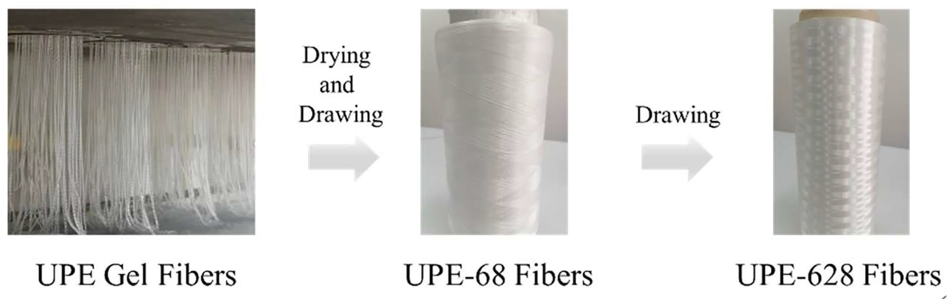
Optical images of UPE fibers at multiple production stages.
The mechanical properties of UPE fibers during step-by-step drawing processes
The mechanical properties of the UPE fibers were investigated after each processing stage. The strength and modulus of the fibers increased significantly with the elevation of the drawing ratio, which was mainly because that the folded-chain crystals of the fibers were gradually converted into extended-chain crystals under hot drawing conditions. The change of mechanical properties of UPE fibers in the process of step-by-step drawing is depicted in Figure 3.

Mechanical property changes of UPE fibers during multiple drawing stages: (a) fiber strength and (b) initial modulus changes of UPE-68, UPE-408, UPE-628, and UPE-628 fibers.
As can be seen from Figure 3(a), the strength of UPE-68 fiber (9.55 cN/dtex) increased sharply as the drawing ratio increased. A final strength of 48.1 cN/dtex with a coefficient of variation (CV) of 11.6% of the UPE-628 fiber was achieved. Figure 3(b) depicts the modulus of UPE fibers. It is obvious that the modulus raised up remarkedly from the initial 232.6 cN/dtex (UPE-68 fiber) to 2213 cN/dtex (UPE-628 fiber), which again demonstrates that the application of drawing force is beneficial to the enhancement of the mechanical properties of the UPE fibers.
The morphology changes of UPE fibers during step-by-step drawing processes
The extrusion of the UHMWPE spinning solution from the spinneret nozzle was conducted under a temperature of 180℃ and a pressure of 2.0 MPa. The organic solvent in the spinning flow, decalin (DHN), would be rapidly evaporated immediately when extruded from the spinneret, due to the instant decrease in the temperature and pressure. Theoretically, a flash evaporation of the decalin solvent could occur when the high-temperature UHMWPE/decalin solution (around 180℃) is extruded from the spinneret under a high internal pressure of 2.0 MPa, leading to a crack on the surface of UHMWPE gels due to the instant superficial solvent evaporation, which is detrimental to the subsequent high-ratio draw-down process. To mitigate this issue, the distance between the spinneret and the water-cooling bath was precisely controlled within 5 mm in this work, thereby preventing decalin flash evaporation. The decalin solvent could diffuse to the water bath rather than flash-evaporate into the surrounding environment, facilitating the formation of the solidified UHMWPE gels. Simultaneously, a high-ratio draw-dawn force was applied to prevent the entanglement of the UHMWPE macromolecules.
The morphological characteristics of UPE fibers in different stages were investigated by POM and SEM, as shown in Figures 4 and 5, respectively. It can be observed from Figure 4 that with the increase of drawing ratio, the diameter of the fiber decreased from 25.5 μm to 5.7 μm, and the change was significant. In particular, the diameter of the final ready-made UPE-628 fiber (Figures 4(d) and 5(d)) is 5.7 μm and the fiber is superfine-denier, and no commercially available product has reached this fiber fineness level.

Morphology changes of UPE fibers at various drawing stages. POM Images of (a) UPE-68, (b) UPE-408, (c) UPE-571, and (d) UPE-628 fibers.

Morphology changes of UPE fibers during stepwise drawing stages. SEM Images of (a) UPE-68, (b) UPE-408, (c) UPE-571, and (d) UPE-628 fibers.
In addition, there are some bamboo-shaped or twisted bands on the surface of the dry precursor (UPE-68 fiber, Figure 5(a)), according to the SEM images. With the implementation of the first-stage drawing, the bands on the UPE-408 fibers (Figure 5(b)) surface decreased. No obvious bands were found on UPE-571 and UPE-628 fibers with higher-ratio drawing (Figure 5(c) and (d)). It turns out that the morphological features of the UPE-68 fibers have no impact on the following drawing process and fiber morphologies. The bamboo-shaped bands can be ascribed to that the UHMWPE macromolecular chains suffered slippage and winding due to axial spinneret compression during the extrusion process. The bands gradually disappeared in the following drawing stages and caused no compromise of fibers’ strength and modulus, which is consistent with the results proposed by Vlasblom. 5
During the drawing process, the folded UHMWPE macromolecular chains are forced to improve and convert to extended chains with fewer fiber fracture, higher melting temperature, and better mechanical performance. It can be seen from Figure 5(a) that the UPE-68 fiber with unoriented or low-oriented layered crystals transforms into UPE-408, UPE-571, and UPE-628 fibers with a smoother and more dense appearance when applied with the elevated drawing ratios. The longitudinal grooves on the surface of UPE-408, UPE-571, and UPE-628 are significantly enhanced due to the molecular structural transformation from a loose network structure to a dense fibrillar structure during the drawing process of the dry precursor (UPE-68 fiber). The capillary grooves gradually densify and deepen as the drawing ratio increases.
DSC analysis of UPE fibers during step-by-step drawing processes
The DSC test results of the relaxed-state UPE fibers show that the unstretched dry precursor (UPE-68) has only one endothermic peak at 145°C (Figure 6). Continuing to draw based on the UPE-68 fiber, a second endothermic peak appeared on the DSC diagram (UPE-408). The appearance of the second peak (157.2°C) is the result of the high-ratio drawing. The integrated area of the second peak magnifies and the position of the second peak shifts with the elevated drawing ratio. The position representing in temperatures of the first peak and the second peak for UPE-408, UPE-571, and UPE-628 fibers are 149.05, 157.2, 148.71, 160.28, 147.56, and 158.94°C, respectively. The position of the second peak on the DSC diagram moves to a higher-temperature region with the increase in the drawing ratio. This maybe because of the higher crystallinity of the UPE fibers with higher drawing ratios. According to Table 1, the crystallinity of UPE-68, UPE-408, UPE-571, and UPE-628 fibers are 70.55%, 84.37%, 87.86%, and 89.78%, respectively, which can be calculated by dividing the integrated △Hendotherm of the prepared UPE fibers by the standard pure UHMWPE heat fusion (△Hf). 42 The experimental results are consistent with those in Xu et al.’s research. 43 In their work, only one peak at a lower temperature is shown in the DSC spectrum for the low ratio drawn UPE fibers, which was attributed to the melting temperature of melt-crystallized polyethylene. With a higher drawing ratio, the melting endotherms move to higher temperature regions, suggesting the disappearance of the folded-chain crystals (kebab structure). For higher ratio drawn fibers, the second peak was considered an endotherm peak of the newly formed hexagonal crystals with a higher melting temperature. The elevated temperature melts the orthorhombic crystals in the UPE fibers and converts the crystals into hexagonal crystals through solid-state transformation. It is believed that the endotherm peak shift is related to the processing parameters, especially the drawing ratio and drawing temperature.

DSC Curve of UPE fibers during multiple drawing stages.
Crystallinity of UPE fibers at different drawing stages.

Literature reveals that the first peak has never been found to appear at a temperature higher than 140°C. The integrated area of the first peak and the second peak gradually declined and increased, respectively. Finally, the intensity, and the integrated area of the second peak of UPE-628 fibers are higher than those of UPE-68 fibers, according to the DSC analysis.
The high-ratio drawing process transforms the folded-chain crystals inside the UPE fibers into highly oriented extended-chain crystallized microfibrils. During the drawing process, the aggregates represented by large lamellae were first decomposed into slightly oriented lamellae. Then, the lamellae rotated and unwrapped along the drawing direction, eventually converted to the microfibrillar structure with extended-chain crystals. The microfibrillar structure consisting of orientated-folded lamellae crystals and extended-chain crystals connecting lamellae crystals results in more tightly compacted macromolecules with higher crystallinity.
WAXD analysis of UPE fibers during step-by-step drawing processes
There have been numerous reports on the WAXD characterization of the structure of UPE fibers, revealing that WAXD is a robust characterization technique in this type of research. WAXD was also employed in this work to demonstrate the crystallinity of the prepared UPE fibers. As shown in Figure 7, the X-ray patterns of the fibers at different processing stages reveal two distinct diffraction rings, which could be attributed to the diffraction signal of the 110 (2θ = 21.5°) and 220 (2θ = 23.8°) surfaces in the orthogonal polyethylene unit cells, respectively. As the drawing ratio increases, the diffraction rings first weaken and then gradually strengthen. Three types of crystals coexist in the UPE fibers, including folded chains and extended chains in orthogonal crystals, as well as monoclinic crystals (001 crystal surface, 2θ = 19.4°). Crystallization peaks at 21.5° and 23.8° account for most of the crystallization peaks of the prepared UPE fibers.
Macromolecular aggregation structural evolution analysis of UPE fibers during multiple drawing stages. WAXD spectrum of (a) UPE-68, (b) UPE-408, (c) UPE-571, and (d) UPE-628 fibers.
Figure 7 also shows that UPE-68 has relatively strong crystallization, and a certain amount of monoclinic crystals may exist in the fibers. A minor X-ray diffraction signal could be observed from Figure 7(a), which could be attributed to the monoclinic crystals. The monoclinic crystals weakens or even disappears as the draft ratio increases (Figure 7(b) and (c)). Along with the increasing temperature and drawing ratio, the crystallinities increase, accompanied by the increased content of extended-chain and monoclinic crystalline phases, as shown in Figure 8.

WAXD Intensity of UPE fibers during the step-by-step drawing process.
The WAXD intensity of UPE fibers at different stages are extracted from Figure 7 to provide more intuitive analysis. The intensity of UPE-68 first declined after the fore-spinning pre-drawing process (UPE-408). After the following high-ratio hot-drawing process, the WAXD intensity sharply increased. Especially, the WAXD intensity of the finished UPE fiber (UPE-628) demonstrated the highest intensity in three crystal surfaces, which proves the high-ratio hot-drawing process promotes the formation and conversion of the crystalline structure of the UPE fibers. The tremendous WAXD intensity at 2θ = 19.4°, 21.5°, and 23.8° in UPE-628 could be assigned to a large amount of the crystals in the ready-made UPE fibers, which also proves that a higher degree of crystallization was achieved thanks to the higher drawing ratios.
SAXS analysis of UPE fibers during step-by-step drawing processes
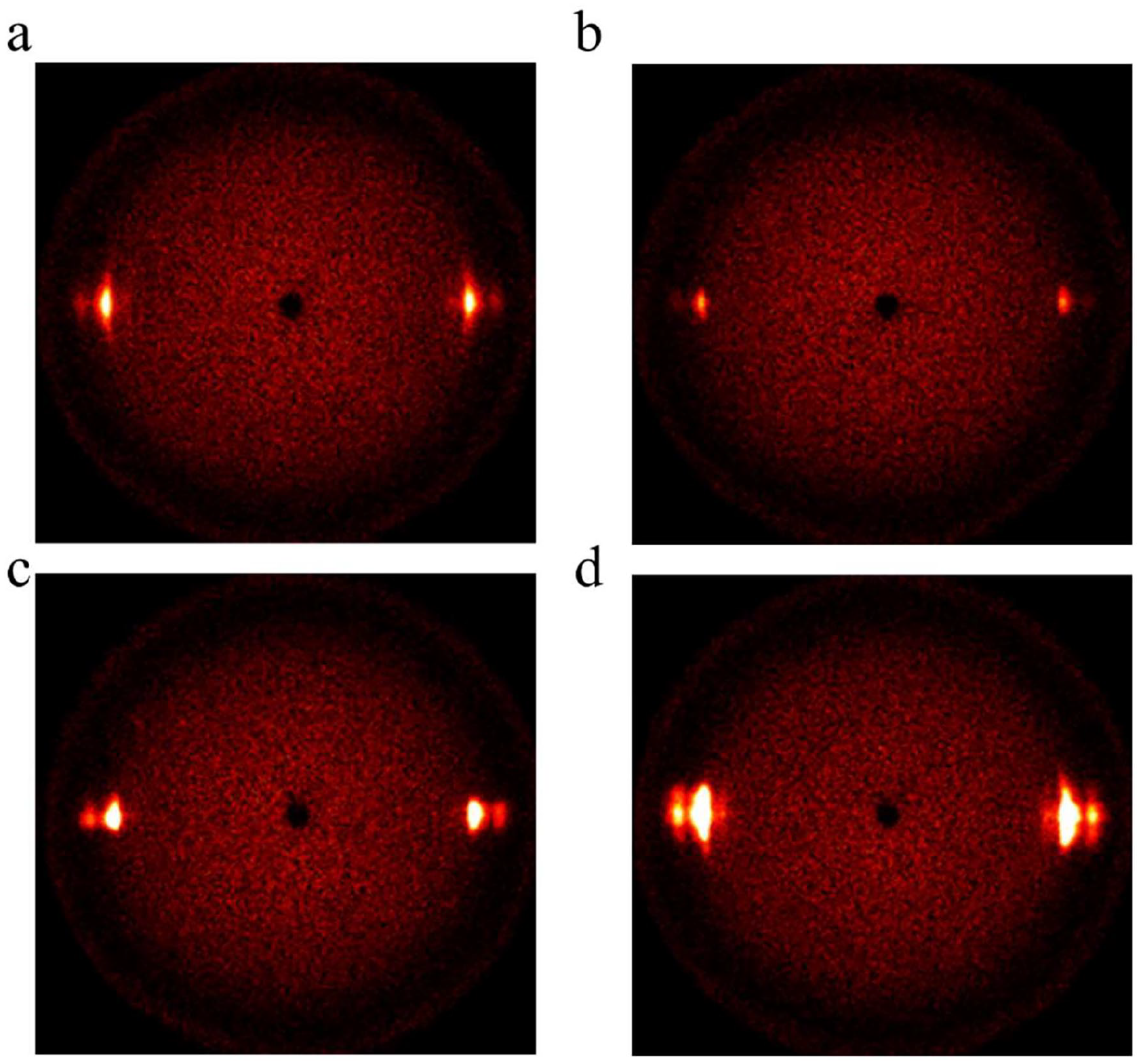
The evolution of the micromolecular structure of the prepared UPE fibers during the dry spinning process was further confirmed by SAXS, which can be referred to in Figure 9. Under the application of drawing force, a shish-kebab structure was formed in the initial processing stage (UPE-68, Figure 9(a)). The SAXS signals on both sides of the scattering center could be attributed to the kebab crystal, while the central one could be attributed to the shish crystal. As the drawing ratio increases (UPE-408, UPE-571, and UPE-628), the kebab crystal disappears, and the shish crystal increases, as shown in Figure 9(b)–(d). During the drawing process, the SAXS signal in the center remains unchanged, yet the SAXS signals on both sides gradually disappear. Whereas, due to the sharp decrease in fiber diameter (from 25.5 μm to 5.7 μm) at the late drawing processes (UPE-571 and UPE-628), the central SAXS signal representing the shish crystal is not as strong as those of the UPE fibers in the early processing state with slighter drawing force.

Macromolecular aggregation structural evolution analysis of UPE fibers during multiple drawing stages. SAXS spectrum of (a) UPE-68, (b) UPE-408, (c) UPE-571, and (d) UPE-628 fibers.
To further study the aggregation structure evolution of UPE fibers in a bit more detail, SAXS analysis on UPE-68 fibers with lower-ratio drawing ratios (from 1.5 times to 2.5 times) was implanted, which is depicted in Figure 10.

Macromolecular aggregation structural evolution analysis of UPE during lower ratio drawing process. SAXS spectrum of (a) UPE-68, (b) UPE-68a, (c) UPE-68b, and (d) UPE-68c fibers. The drawing ratio of UPE-68, UPE-68a, UPE-68b, and UPE-68c are 1, 1.5, 2.0, and 2.5, respectively.
Compared to UPE-68 fiber, the SAXS spectrum of UPE-68a fiber with a drawing ratio of 1.5 times (Figure 10(b)) maintains stronger central signal and the two side signals representing the shish crystal and kebab crystal, respectively. When UPE-68 fiber was drawn to 2.5 times (Figure 10(d)) of its original length (UPE-68, Figure 10(a)), the SAXS signals on both sides disappeared, demonstrating that the kebab crystals were largely converted into shish crystals. The kebab signal initially increased and subsequently decreased under lower ratio drawing force. The shish signal (central SAXS signal) kept strengthening during the stretching process, revealing that kebab crystals transformed into shish crystals under the function of the drawing force. Finally, all SAXS signals on both sides representing kebab crystals disappeared, which proves the complete crystal transformation from kebab to shish, which is responsible for the increased mechanical properties of the final UPE fibers.
AFM analysis of UPE fibers before and after the high ratio stretching process
To investigate the macromolecular structure evolution of UPE fibers more intuitively before and after the high ratio stretching process, the atomic force microscopy (AFM) was employed to depict the surface and crystalline of the microfibrils inside the UPE fibers. AFM Was widely and frequently utilized as a roust microscopy to directly observe the morphology of the UPE fibers, as well as their macromolecular structures.40,44 It is considered that the AFM could provide a more thorough depiction of the macromolecules in nanoscale with the assistance of its unique probe and laser system.
As is known to all, a single UPE fiber consists of multiscale fibrillar hierarchy such as macro fibrils, microfibrils, epitaxial features, etc. 40 The maco fibrils consist of microfibrils and epitaxial features that are mainly lamellar crystals. By using AFM, the microfibrils and crystalline evolution inside the UPE fibers could be clearly differentiated. The width of the microfibrils of the lower ratio stretched UPE fiber (UPE-68) could be measured in Figure 11(a), reaching an average diameter of 302 nm, which is way lower than the fiber diameter of 25 μm. In addition to the fibrils on the surface of the UPE-68 fiber, there is clear evidence of the ordered lamellar structures that are oriented perpendicular to the fibril axis, which could be assigned to the epitaxial features as shown in Figure 11(b). The average width of the lamellar crystals is measured as 31.17 nm. As the stretching ratio elevated, the lamellar crystals disappeared and new oriented structure were formed, as can be seen from Figure 11(c). The oriented structure in UPE-628 fiber was further stretched to an average width of 63.19 nm. The new oriented structure could be attributed to the shish crystals that were formed after high ratio stretching process. The crystal width evolution before and after stretching correlate well with the experiment results in the literature.40,44 The effective crystal domain size was elongated with the elevated stretching ratio, which was calculated and confirmed by WXRD results. The crystal width elongation from UPE-68 to UPE-628 is consistent with the shish-kebab theory during the stretching process, where the lamellar kebab crystals were melted and converted to the shish crystals due to the high ratio stretching force. The AFM results support the above WXRD and SAXS results we conclude.

AFM Images of UPE fibers at various stretching stages. (a) AFM Image depicting width of microfibrils of UPE-68 fiber. (b) AFM Image depicting epitaxial features of UPE-68 fiber. (c) AFM Image depicting shish structure of UPE-628 fiber.
Conclusion
The mechanical properties and macromolecular aggregation structure evolution of the UPE fibers were thoroughly investigated by manipulating the industrial processing parameters during production. A UHMWPE/DHN spinning solution was prepared and spun into UPE fibers employing a water-bath-assisted curing and dry spinning process. Multiple high-ratio drawing processes were implanted on the initial UPE gel fibers to improve their mechanical properties and crystallinity. The total drawing ratio of UPE fibers after the preparation reaches up to 628 times. The UPE fiber diameter was minimized to 5.66 μm with the assistance of drawing force. The tensile strength and modulus of the ready-made UPE fiber could reach as high as 48.1 cN/dtex and 2213 cN/dtex, respectively, thanks to the high ratio drawing process. The crystallization degree of the final UPE fiber attained 89.78%, which is significantly improved compared with the original UPE dry precursor. Under drawing force, the folded-chain crystals in UPE fibers are stretched, melted, and converted into extended-chain crystals with better-developed crystal structures, which enables a denser macromolecular structure. The prepared UPE fibers are featured for their high mechanical property and minimum denier. This work may provide more insights into manipulating and developing industrial production of UPE fibers.
Footnotes
Acknowledgements
The authors also want to express great thanks to the unconditional support from Sinopec (Beijing) Research Institute of Chemical Industry Co., Ltd. (BRICI).
Declaration of conflicting interests
The author(s) declared no potential conflicts of interest with respect to the research, authorship, and/or publication of this article.
Funding
The author(s) disclosed receipt of the following financial support for the research, authorship, and/or publication of this article: This work was financially supported by China Textile Academy Co., Ltd. (CTA).