
Abstract
Few studies combining experimental and theoretical analyses of pultruded fiber-reinforced polymer (FRP) composites are available in the literature. In this study, experimental methods and a nonlocal theoretical approach were used to investigate the flexural performance of pultruded glass-FRP (GFRP) plates. In the theoretical method used, the Eringen’s nonlocal elasticity theory was adopted so that small-scale material effects on pultruded FRP composite plates were taken into account. Based on the plate theory of high-order shear deformation, the kinematic relationships of the composite plates were established. The stiffness matrix coefficients and tangential stiffness matrix were shown along with the nonlocal force vector. Also, finite element modeling was performed with the help of ABAQUS for the accuracy of experimental and theoretical results. For the analysis, a variety of laminated plate types were taken into consideration. The flexural performance was investigated utilizing flexural tests under point and distributed loads. To comprehend the behavior of the pultruded GFRP plates more fully, macro mechanical damage analyses were carried out. Numerical values were compared with experimental findings, theoretical solution results, and finite element simulation results which were found to be very similar.
Keywords
Introduction
Pultrusion-produced composite materials are used extensively all over the world. The use of profiles created by the pultrusion technique has gained more attention in recent decades from a variety of sectors.1–3 Alternative materials such as glass fiber-reinforced polymer (GFRP) are frequently employed in manufacturing or construction for high-performance applications.4–7 Fiber-reinforced polymers (FRPs) stand out as ideal materials for serving as structural load-carrying elements due to their exceptional advantages.8–11 Their superior properties, including high strength and durability, make them well-suited for bearing structural loads effectively.12–20 As a result, FRPs are widely utilized in various industries where robust and reliable structural components are essential.21–25 Pultrusion is one of the most efficient of various composite manufacturing processes.26–29 The benefits of pultrusion over other composite production techniques include its high production rate, 30 better efficiency,31,32 lower production costs, 33 the ability to produce composite materials at a much faster pace, and the capacity to create profiles with almost infinite lengths. 34 Matrix-based composites come in thermoplastic and thermoset varieties. 35 Unidirectional fibers or fiber reinforcement in the form of fabric are drawn through an impregnation bath for thermoset pultrusion. 36 The impregnated section is then passed through collimating plates to remove surplus resin before being placed into a heated forming die. After cooling, the component is ready for use after being impregnated with hot melt thermoplastic polymer with fiber reinforcing. The cutting saw is utilized to cut the formed profile to the right length once the polymerized composite has been pulled from the forming die by the pulling mechanism. 37 Generally, pultruded components are formed of an embedded fiber discontinuous phase known as reinforcement and a continuous polymeric phase known as the matrix. Fillers can occasionally be used to boost the interaction between the matrix and reinforcement, reduce costs, or enhance the matrix’s properties.38–42 Many researchers have documented or assessed the mechanical properties of the component elements to examine the mechanical behavior of pultruded pieces. 43 Glass, carbon, or aramid fibers are typically used to make the pultruded FRP composites. 44
In order to evaluate multilayered composite structures, many models were created as the usage of composite materials. The literature has evolved the Kirchhoff plate theory, first-order and higher-order shear deformation theories, also known as equivalent single layer theories, to assess isotropic and composite plates.45–51 Various mathematical models have been extensively presented by Tornabene.52–56 The Kirchhoff plate theory, sometimes referred to as the classical plate theory, is appropriate for thin plates since it disregards interlaminar shear deformation and rotational inertia. The Kirchhoff plate theory produces false findings for composites by ignoring transverse shear effects. Based on Reissner and Mindlin assumptions,57,58 the first-order shear deformation plate theory is presented for the thick plates and includes the transverse shear effects with a linear change of transverse shear strain through the plate thickness. 59 This theory is necessary as a shear correction to account for the variability of transverse shear stress and shear strain through thickness. Since it considers a linear transverse shear distribution across the plate thickness, the first-order shear deformation plate theory does not satisfy the requirement of zero transverse shear stress at the top and bottom surfaces of plates. Other factors that affect the shear correction factor are plate border circumstances, loading conditions, layer orientation, and geometrical features. 60 More accurate models, including higher-order shear deformation theories, assume quadratic, cubic, and more variations surface parallel displacements throughout the whole length of the laminates to forecast how the structure would behave for thick to thin portions.61–64
In contrast to experimental testing, modifications of conventional classical continuum theories, which mathematically estimate the size effects, may be a more affordable and trustworthy alternative technique of analysis. Classical theory in continuum mechanics assumes that stress at an arbitrary point is a function of its own stress, thus, it cannot capture the scale effect of advanced composites in microstructures. 65 Recently, the accessible non-classical continuum models of nonlocal elasticity theory, modified couple stress theory, and strain gradient theory have been applied in the mechanical analysis of small-scale structures. 66 To account for the scale effect in elasticity, the nonlocal elasticity theory has been proposed by Eringen. 67 By include extra degrees of freedom in the kinematics assumptions for each material point, nonlocal elasticity models may be created.68–74 For the axisymmetric bending analysis of circular plates under general stress, Duan and Wang 75 deduced precise solutions of the nonlocal Kirchhoff plate theory model. The nonlocal parameter’s impacts on the circular graphene sheets deflection, radial moment, circumferential moment, and shear force were examined under uniform loads, with either clamped or just supported boundary conditions. Ma’en and Al-Kouz 76 have focused into the free vibration analysis of nonlocal orthotropic Kirchhoff plates. Kirchhoff plates are described at the micro/nanoscale by the nonlocal elasticity theory of Eringen, which takes into account the small-scale effect. Both the first-order shear deformation plate theory and the nonlocal Kirchhoff plate theory models for graphene sheets were introduced by Kananipour, 77 however, they were used in the static bending analysis with differing boundary conditions. For functionally graded circular plates, Hosseini-Hashemi et al. 78 created a nonlocal first order shear deformation plate theory. Also, closed-form solutions were found for the natural frequencies of plates under various boundary conditions. Using von Karman nonlinear stresses, Golmakani and Rezatalab 79 provided a nonlinear nonlocal first-order shear deformation plate theory model for the nonlinear bending analysis of orthotropic embedded plates. Based on the revised plate theory, Narendar 80 suggested a nonlocal higher-order shear deformation theory model for the buckling analysis of isotropic nanoplates. Belkorissat et al. 81 developed a simple nonlocal higher-order shear deformation theory model for functionally graded nano-plates. Based on the quasi-3D sinusoidal theory with five unknowns, Bessaim et al. 82 developed a nonlocal quasi-3D model for the dynamic analysis of plates.
Several scholars utilize the usual concept that the highest deflection occurs in the mid-plan of the thickness. When the deflection field’s fluctuation across the thickness is taken into account, this assumption appears to be almost incorrect. The transverse deflections and thickness changes are confirmed to cause the highest deflections to occur at the plate’s top surface.
Analytical techniques as well as numerical approaches can be employed to solve the governing equations resulting from dimension dependent models. Nevertheless, owing to straightforward geometry, stress, and boundary conditions, the use of analytical techniques is restricted to a certain advanced composite. For instance, the Levy approach only works with rectangular plates that have two opposing sides that are simply supported, and the remaining two sides can have any arbitrary boundary condition, whereas the Navier method only works with rectangular plates that have simple supports on all four sides. It is impracticable to search for analytical solutions to real-world problems such as generic geometry, loading, and boundary conditions since size dependent models are more mathematically difficult than classical models. In order to tackle such problems, numerical approaches like the finite element method (FEM), Ritz and Galerkin methods, differential quadrature method, meshless method, etc., are known as some of the most efficient methods.83,84 FEM is the most potent instrument among the many numerical approaches, and it is frequently employed for the study of structures.85,86 Reddy 87 created the nonlinear nonlocal Kirchhoff plate theory and first-order shear deformation plate theory models for the von Karman-based nonlinear bending analysis of nano-plates. For the creation of finite element solutions, the variational statement of these models was also supplied. Reddy and Chao 88 developed a displacement FEM for the analysis of thick plates, based on first-order plate theory, describing the transverse shear. Fantuzzi et al. 89 studied free vibration analysis of laminated composite plates using FEM and differential quadrature techniques based on Fourier broadening.
It is evident from the literature analysis that surface effects and small-scale effects are crucial in micro structural plates exposed to compressive in-plane loads, and as a result, the bending problem of laminated composite plates has to be examined in light of these effects. Throughout the past decade, substantial efforts have been given to the creation of size-dependent models based on higher-order continuum mechanics method. Currently, there is no combined research on pultruded GFRP plates in terms of experimental application, nonlocal theories, and numerical modeling and analysis. In this study, bending analyses of GFRP plates produced by pultrusion method were investigated experimentally, numerically, and theoretically. Since the pultrusion consists of GFRP plate veil layer, reinforcement phase, and matrix layer with various sands, finite element solution based on nonlocal elasticity theory was performed. It covers several layer orientations for rectangular plates with varying sizes. The Eringen’s nonlocal elasticity theory is utilized here. The weak forms are derived using the virtual displacement concept, and the displacement finite element models are created using the weak forms. In the polymer matrix of the modeled system, shear and transverse forces coexist. A rectangle conforming element with four nodes and eight degrees of freedom are employed. Together with the nonlocal force vector, the stiffness matrix coefficients and tangent stiffness matrix are demonstrated. Experimental, numerical, and theoretical results are presented comparatively. In addition, macro damage analysis is conducted.
Experimental study
This section uses test procedures on specifically manufactured pultruded GFRP composite plate specimens to examine the accuracy of theoretical and numerical solution techniques as well as the behavior of the material (Figure 1). The fibers used in the pultruded GFRP plates are E-glass. 4800 tex fiber bundles were utilized in the glass roving and 450 g/m2 nonwoven fabric was employed for the glass mat. In compliance with standards, GFRP composite plates were used for the testing.
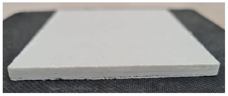
Pultruded GFRP plate.
The elastic modulus and shear modulus of the square pultruded GFRP sections were determined previously by Madenci et al.38,39 and are listed in Table 1.
Mechanical properties of pultruded GFRP.

Specimen design
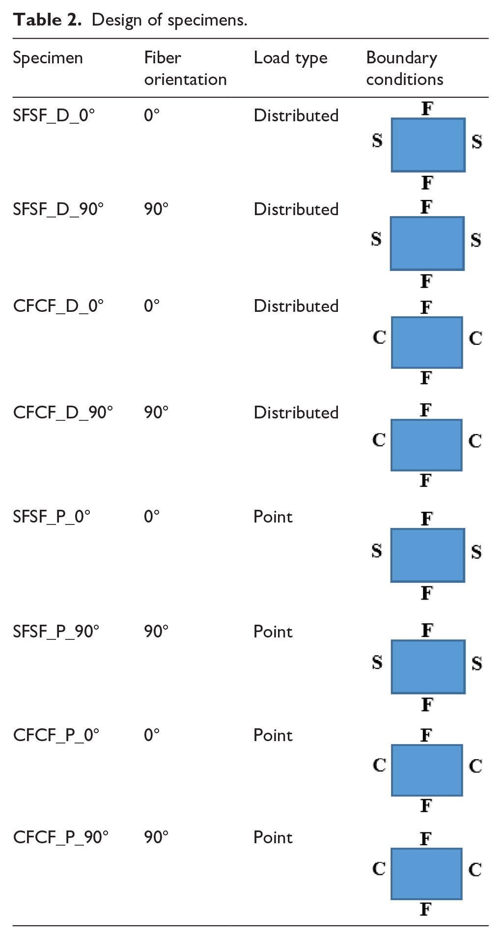
The pultruded GFRP strip is divided into four groups, resulting in a total of 24 examples. Polyester resin and GFRPs were used to create these specimens. The design properties of the pultruded GFRP specimens are given in Table 2. The thickness of all specimens was 6 mm. The plate section was 130 mm × 130 mm.
Design of specimens.
Burnout test
The ratios of matrix and fiber of the pultruded GFRP plates were determined using a burnout test on the specimens produced from the strip. The combustion test was carried out in accordance with the ASTM D-2584 standard. The pultruded GFRP specimens, which were made by slicing the specimens into pieces 5 cm wide, were cooked in the oven at 600 °C for an hour. The matrix fully burnt off at this period, leaving only the fibers. Once the specimens were taken out of the furnace, fiber weights were calculated. Following the burnout test, the glass and veil layers that were removed in accordance with the direction of the fibers are depicted in detail in Figure 2.
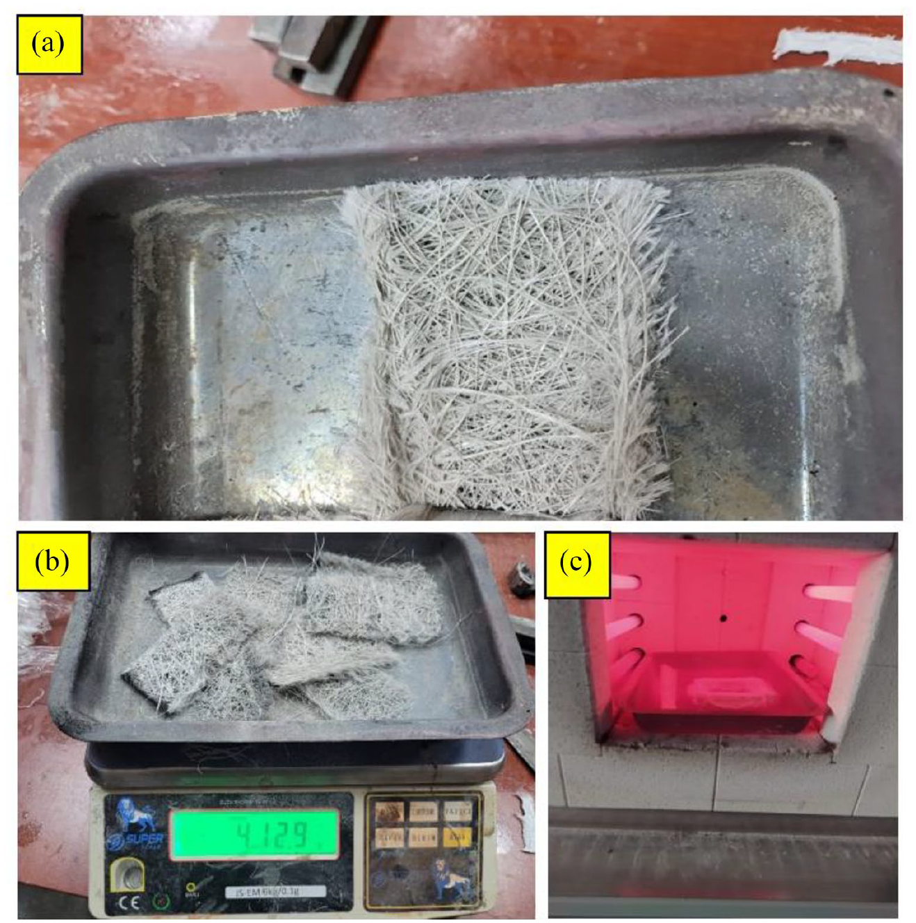
Burnout test: (a) FRPs of plate, (b) weighing after burning test, and (c) oven.
Tensile test
The pultruded GFRP exhibits varying resistance to pressures coming from various directions because of its fibrous and orthotropic structure. To ascertain the tensile characteristics of the pultruded GFRP composite beams, tensile tests were carried out both parallel and perpendicular to the direction of the fiber. On the traction machine with the hydraulic loader, tensile force was delivered to the ready specimens at a steady pace. By gathering the essential information, it was possible to compute the mechanical properties of the pultruded GFRP. A universal testing equipment was utilized to test the samples with nominal length, breadth, and thickness measurements of 250 mm × 25 mm × 3 mm under tensile pressures in order to assess their tensile strength. The technique outlined in ASTM D3039 was used.90,91 One mm was applied each minute by the forces (Figure 3).
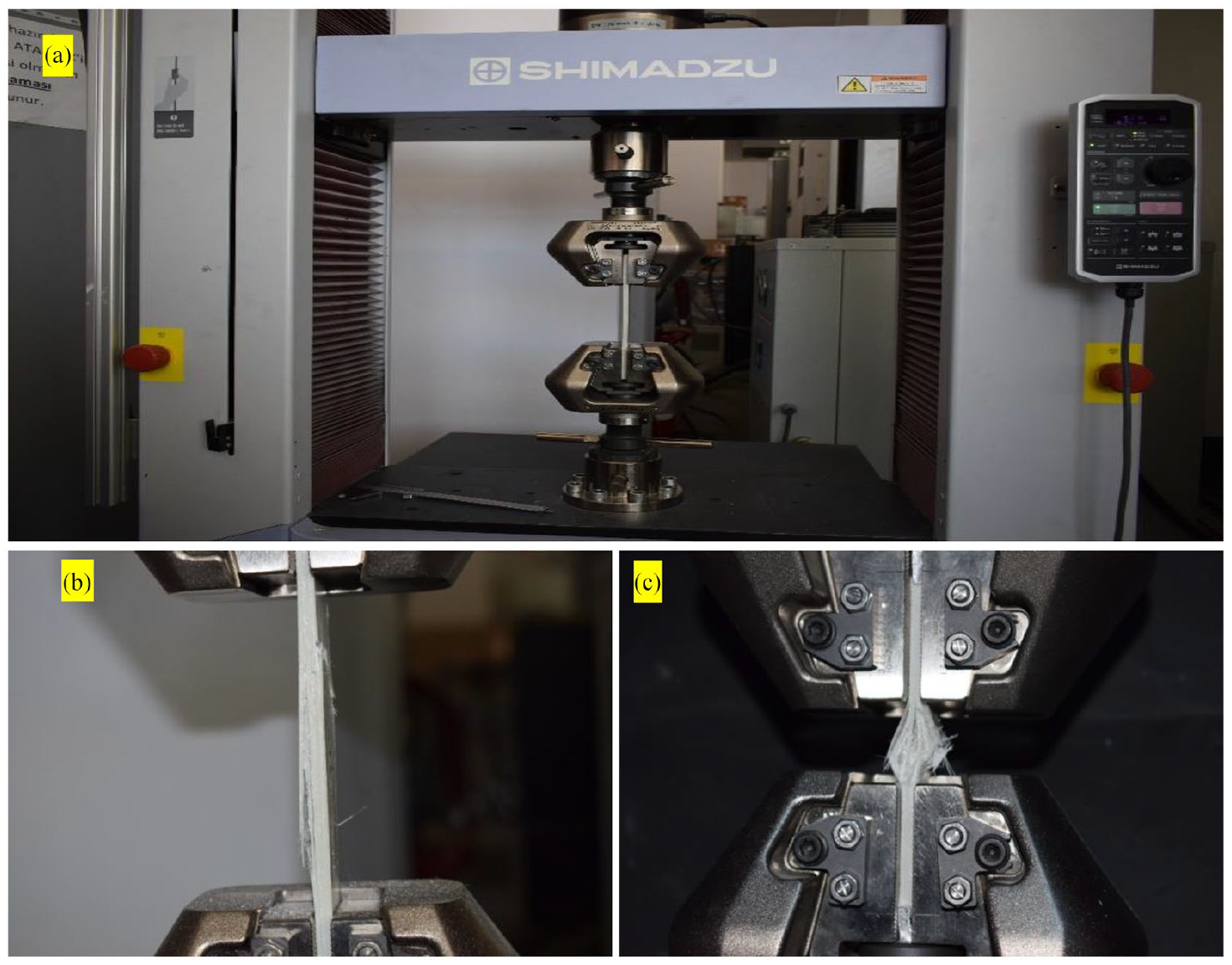
(a) Tensile and compressive tests setup, (b) tensile test specimen, and (c) compressive test specimen.
Compressive tests
The samples, which had dimensions of 150 mm × 25 mm × 3 mm, were put under axial compression to find out how strong they were (length-width-thickness). The distance between the noses was 40 mm. The compressive properties of stiff polymers were evaluated using the ASTM D695 standard test procedure. 92 One mm was applied each minute by the forces (Figure 3).
Flexural test setup
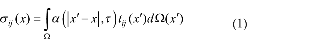
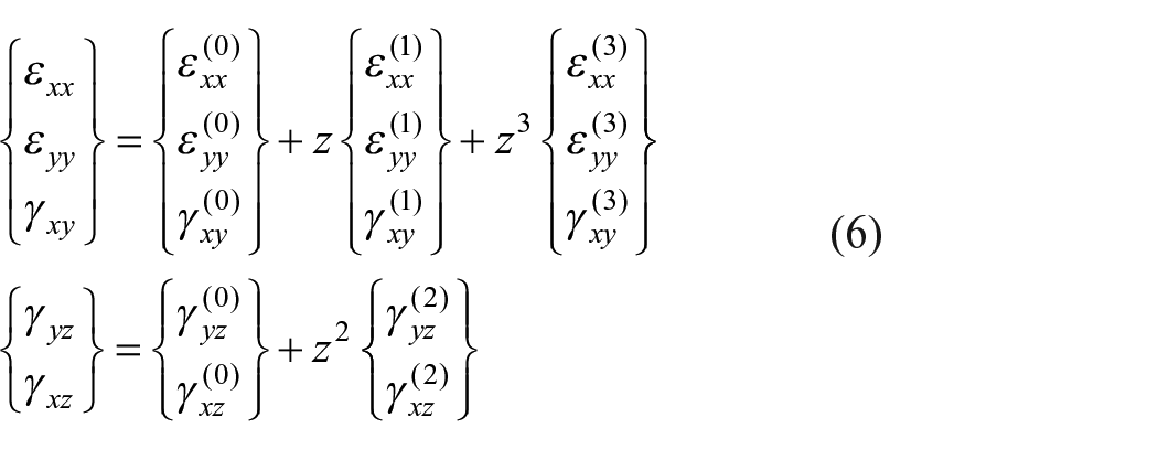
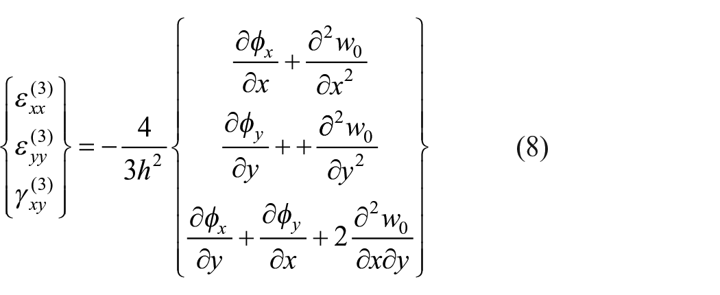
A comprehensive experimental study was performed to comprehend the behavior of the pultruded GFRP plates under different loading conditions. Three different parameters were selected. These are boundary conditions, type of loading, and fiber direction. For boundary conditions simple-free-simple-free (SFSF) and clamped-free-clamped-free (CFCF) were selected. In order to provide clamped boundary conditions, the pultruded GFRP plates were squeezed via steel plates using clamps. For loading, point loading (P) and distributed loading (D) were adopted. Two different directions were considered as 0° and 90°. The specimens were tested under servo controlled hydraulic piston with capacity of 50 t. The load and displacement values were recorded. The speed of experiments was 2 mm/min. The loading was terminated when excessive deformation or reduction in loading was detected. For each configuration, three repetitions were done to ensure accurate findings. Figure 4 illustrates the setup of the flexural test.
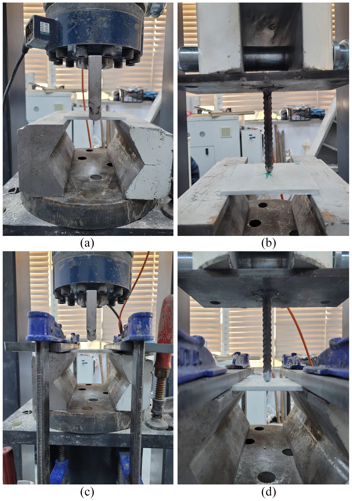
Flexural test setup and configurations: (a) specimen SFSF_D, (b) specimen SFSF_P, (c) specimen CFCF_D, and (d) specimen CFCF_P.
Theoretical formulation
Nonlocal elasticity model
Eringen maintains that the stress at a point of comparison in a continuum system requires not only the strain at that point but also the strains at all the nodes. This presumption requires that the constitutive description has a length scale parameter. The strain tensor at every other place on an elastic body is what determines the stress tensor at point x, in accordance with nonlocal elasticity theory.5–7 For homogeneous elastic solids, the nonlocal stress-tensor components
where

Because the component problem’s integral form solution is complicated, the following simplified differential form equation can be utilized instead.

where
As opposed to the linear algebraic equations between the stress resultants and strains in a local theory, the nonlocal theory results in differential relations involving the stress resultants and the strains. In equation (4), we present these relations for homogeneous isotropic beams under the assumption that the nonlocal behavior is negligible in the thickness direction. The nonlocal constitutive relationship can be written as:

Kinematic relations
Transverse shear stresses in laminated composite plates cannot be ignored when assessing structures since they have lower shear modulus than in-plane modulus. Transverse shear strains and shear stresses can vary in a parabolic manner and are not required to use a shear correction. According to Reddy, 93 the displacement field has been enlarged to the third degree of the thickness coordinate.

where

Geometry of a laminated composite plate.
The linear transverse and in-plane shear stresses are provided by:
where


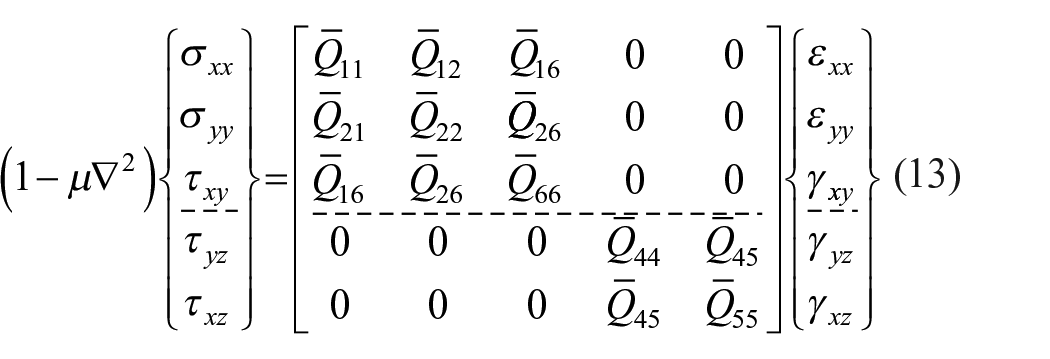
Stress-strain relations
The layer’s material behavior is described via the Eringen’s nonlocal elasticity model, which relates the local stresses
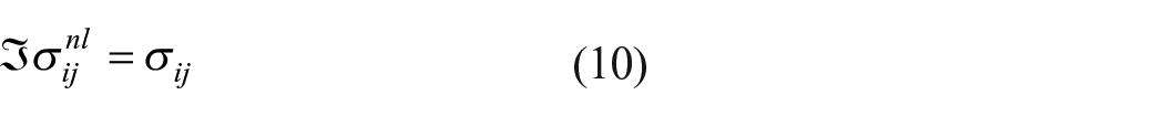
Equation (10) may be used to obtain the relationships between the local and nonlocal stress resultants as:
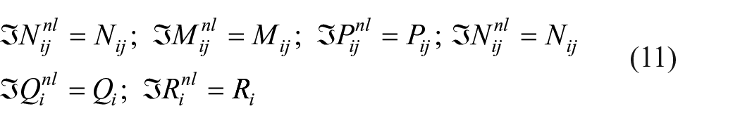

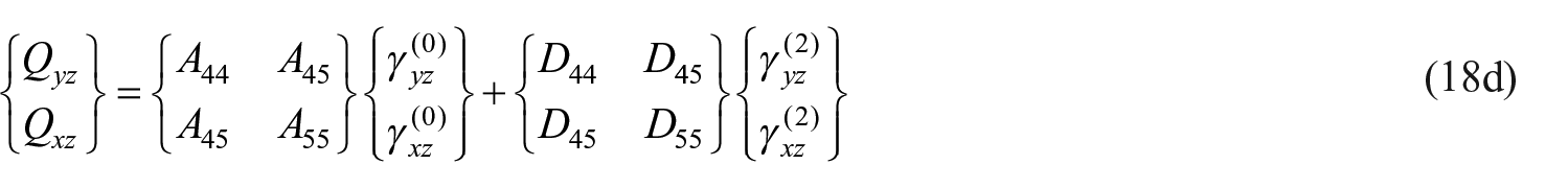
For the pultruded GFRP plate, the constitutive relations of nonlocal theory may be expressed as:
In which

where c is

Governing equations
The concept of virtual displacements, whose variational statement for the k-th layer specialized as the source of the governing equations for a layer inside the laminate, is:

The governing equations of the nonlocal theory are derived in terms of local stress findings by applying the L operator to both sides of the equations:

The following constitutive equations are created by adding the stress-strain relations to equations (12)–(17).


Finite element analysis
The generalized displacements are approximated over an element

Substitution of equation (20) into the weak form equation (17) yields the finite element equations for bending.

The linear stiffness coefficients
The above coefficients are defined using the notation indicated below:


The elements of the force vector are given by:
Numerical study
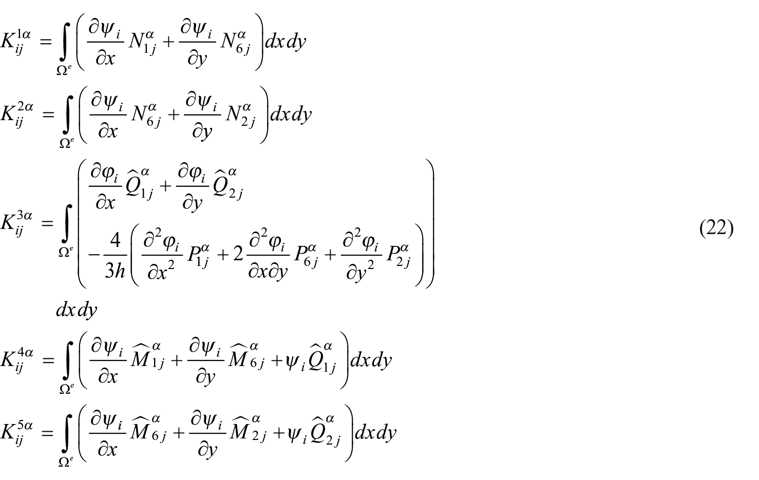
The aim of the finite element analysis is to verify the obtained results. For this purpose, ABAQUS was utilized to construct numerical models. Shell elements with S4R were used for modeling. The Hashin failure criteria were adopted to achieve failure of the plates. Tensile fiber mode, fiber compressive mode, tensile matrix mode, and compressive matrix mode are the failure modes defined in the Hashin failure criteria. These failure modes can be computed from the equations listed in Table 3. The pultruded GFRP was modeled employing the Hashin failure criteria, and the parameters used in the Hashin failure are presented in Table 4. 94 The supports and loading noses were made from solid elements with C3D8R. Steel materials properties with elastic modulus of 200 GPa and yielding of 420 MPa were utilized for the supports. All degrees of freedom were restrained under the supports. Frictional surfaces were considered between the pultruded plate and the supports and loading noses. Friction coefficients of 0.5 was considered. 38 Figure 6 shows the typical numerical modeling.
Hashin failure criteria.

Parameters used in Hashin failure criteria.

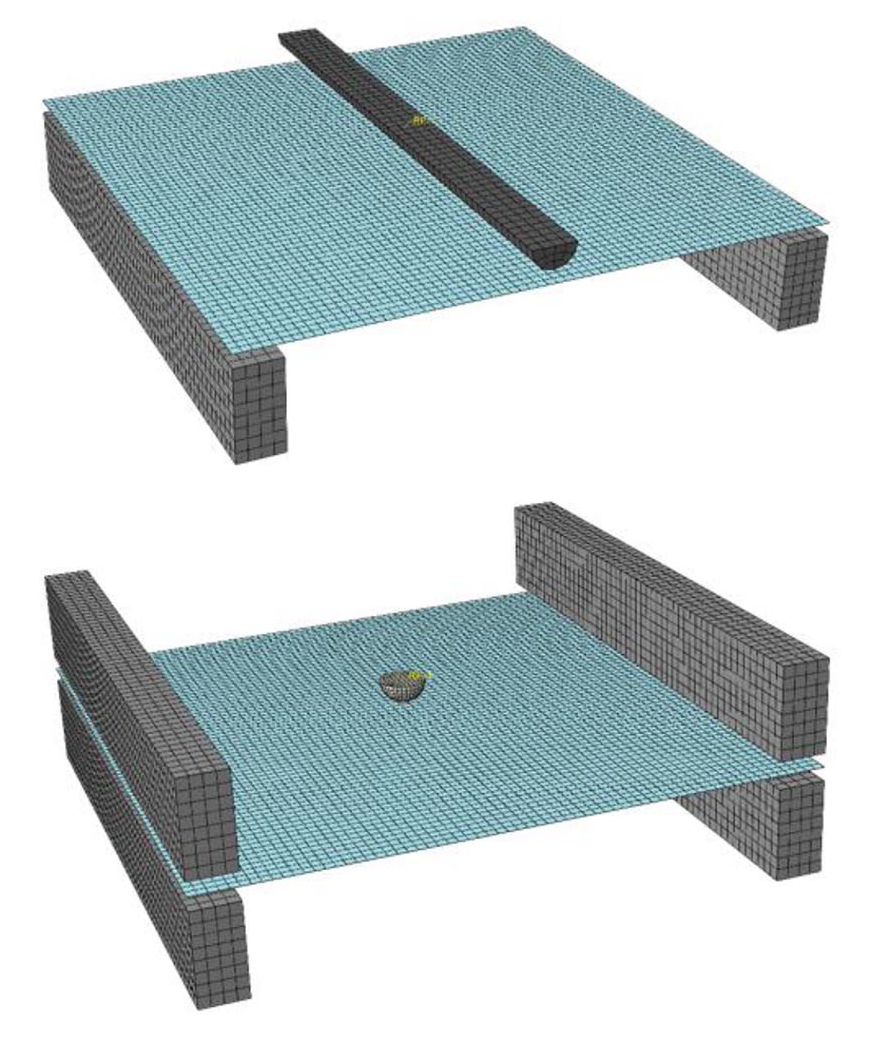
Examples of numerical model and mesh.
The load–displacement graphs obtained from the numerical simulations are exhibited in Figures 7, 9, 11, 13, 15, 17, 19, and 21. The results display that the numerical models captured the obtained results. The accuracy of the numerical models for specimens under SFSF conditions is higher than the specimens under CFCF. The numerical results exhibit higher capacity than those of the tested specimens. The reason for these can be attributed to the setup of the tests. Obtaining perfect clamped boundary conditions in the tests is difficult. Slight rotation of boundary conditions may result in decrease in the capacity.

Load–displacement graphs of specimen SFSF_D_0°.
Results and discussion
Material properties
A pultruded GFRP plate that had been employed in the trials served as the source of the specimen for the burnout test. The specimen was weighed, and volume/density calculations were done before the burnout test. The matrix was totally burnt off as a result of this procedure, leaving just the glass roving, glass mat, and CaCO3 behind. These items were weighed once more. The pultruded GFRP was evaluated and validated in terms of fiber configuration and stacking order after the burnout test. Fiber and matrix volume fractions are found to be 54% and 46%, respectively. E1 and E2 are 20 GPa and 6 GPa, respectively. Tensile and compressive strengths in the longitudinal direction is 320 MPa while these are 80 MPa in the transverse direction. Detailed information about the material properties was reported in theprevious studies.14,15
Macro damage analysis
Load–displacement graphs of the tested pultruded GFRP plates are illustrated in Figures 7, 9, 11, 13, 15, 17, 19, and 21. The tests for each configuration were repeated 3 times. Damage analyses were done based on macro damage photos in Figures 8, 10, 12, 14, 16, 18, 20, and 22. Figures 7–14 display the outcomes for the specimens with distributed loading.

Damages of specimen SFSF_D_0°.

Load–displacement graphs of specimen SFSF_D_90°.

Damages of specimen SFSF_D_90°.

Load–displacement graphs of specimen CFCF_D_0°.

Damages of specimen CFCF_D_0°.

Load–displacement graphs of specimen CFCF_D_90°.

Damages of specimen CFCF_D_90°.
Figures 7 and 8 demonstrate the specimens with 0° under SFSF boundary conditions. The maximum loading was measured as 2.3 kN on average. The first damage was formed in surfacing veil layer. As loading increased, matrix cracks in the fiber directions of 90°, in other words, intralaminar cracks were progressed toward the center of the plate. On the other hand, Figures 9 and 10 depict the specimens with 90° under the same loading and boundary conditions. This time, the maximum loading modified to 10.3 kN. The progressive damage was totally different due to the fiber directions. Initial damage was occurred at veil surfaces. Then, large delamination damage (interlaminar cracks) formed. After this damage, fibers were ruptured, and delamination damage was seen in different locations.
In Figures 11 and 12, clamped boundary conditions were utilized. The damage pattern was similar to the SFSF case. The main failure mode was intralaminar cracks. The maximum loading was measured as 5.4 kN on average which was 134% higher that the case with SFSF. On the other hand, Figures 13 and 14 indicate the specimens with 90° under same loading and boundary conditions. Initially, intralaminar cracks were formed. Then, surface veil damage was progressed. As the loading increased, fibers were triggered to rupture. The maximum loading was measured as 16.5 kN on average.
Figures 15–18 present the findings for the specimens with point loading. Figures 15 and 16 depict the specimens with 0° under SFSF boundary conditions. When the specimen reached its capacity, intralaminar and interlaminar cracks were seen at the center line simultaneously. As the loading increased, intralaminar cracks were seen at different locations toward the supports. The maximum loading was recorded as 1.7 kN on average. On the other hand, Figures 17 and 18 show the specimen with 90° and the same conditions. In this case, a local damage was witnessed at the center of the specimen. Local indication damage was initially detected underneath the loading nose. As the loading increased, the fibers started to break. The damage was not able to propagate toward the ends. The maximum loading was 6.9 kN which was approximately 3 times higher than the specimens with 0° and the same conditions.

Load–displacement graphs of specimen SFSF_P_0°.

Damages of specimen SFSF_P_0°.

Load–displacement graphs of specimen SFSF_P_90°.

Damages of specimen SFSF_P_90°.
Figures 19–22 illustrate the findings for the specimens with clamped boundary conditions. Figures 19 and 20 display the specimens with 0°. The maximum loading was recorded as 3.8 kN. At this loading, intralaminar and interlaminar cracks were observed at the center line simultaneously. Interlaminar cracks were progressed as the loading increased. Figures 21 and 22 indicate the specimens with 90° and the same conditions. The local indication damage was initially detected. Then, intralaminar and interlaminar cracks were witnessed at the center line at the same time. As the loading increased, the fibers underneath the loading nose started to break and intralaminar and interlaminar cracks progressed to grow. The maximum loading was around 7.6 kN which was double of the capacity of the specimens with 0° and the same conditions.

Load–displacement graphs of specimen CFCF_P_0°.

Damages of specimen CFCF_P_0°.

Load–displacement graphs of specimen CFCF_P_90°.

Damages of specimen CFCF_P_90°.
Figure 23 demonstrates the failure modes obtained from numerical study. It is seen that the predicted failure modes are very similar to those observed in the experimental results. HSNFTCRT = 1 represents the fiber tension damage and HSNMTCRT = 1 points out the matrix tension damage. As similar to the obtained experimental results, the specimens with 0° suffered from matrix related damages while the specimens with 90° failed from fiber breakage.

Failure modes of FEM modeling.
Static analysis
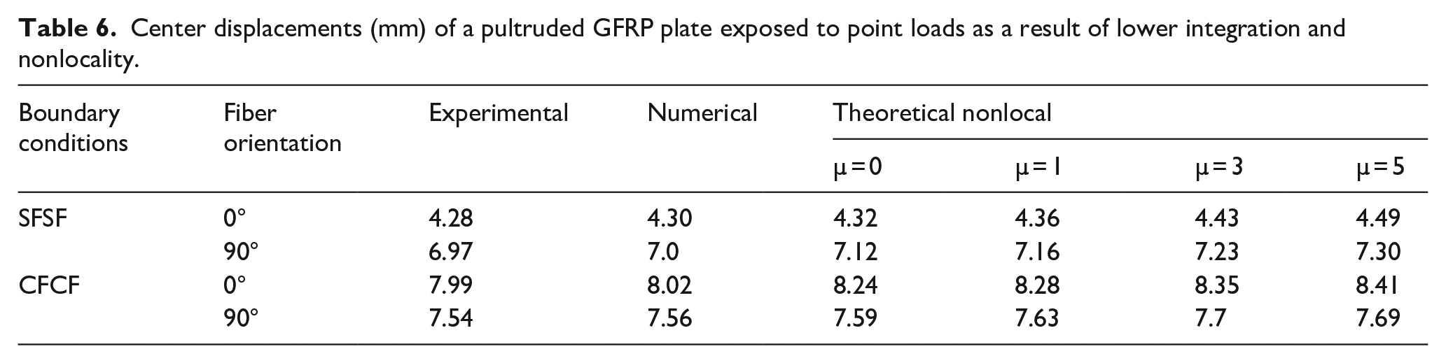
For composite plates under bending load, the theoretical nonlocal high-order FEM and FEM ABAQUS findings were converged. The displacement results were obtained at the halfway point and compared to the experimental displacement findings. The maximum displacement values of the pultruded GFRP plate are presented in Tables 5 and 6. The nonlocal parameter μ has been given a value of 0 to 5. It has been shown that the nonlocality effect has a considerable impact on the displacement value. The value of the displacement increases as the nonlocal parameter rises. Displacement increased as the layer angle changed from 0° to 90°. All the analysis methods captured similar numerical values. As the nonlocal parameter decreased, the displacement value also decreased. If we take the numerical results obtained experimentally as reference, FEM ABAQUS and nonlocal FEM results are very close to the experimental results.
Center displacements (mm) of a pultruded GFRP plate exposed to distributed loads as a result of lower integration and nonlocality.

Center displacements (mm) of a pultruded GFRP plate exposed to point loads as a result of lower integration and nonlocality.
Conclusions
In the present study, by taking into account the Eringen’s nonlocal differential constitutive equations, the governing equations of higher-order deformation plate theory are reformulated using the virtual work principle for the pultruded GFRP composite plates. The nonlocal finite element model is created and the weak forms are obtained. The burnout test, tensile test, and compressive test were conducted to determine the material properties. For the accuracy of the experimental and theoretical results, FEM modeling and analysis were performed in the ABAQUS program. The impacts of anisotropy and nonlocality on the bending behavior of laminated composite plates were illustrated using examples with various stacking sequences and boundary conditions.
• It has been noted that the Eringen’s nonlocal model causes laminated composite plates to lose some of their structural stiffness; as a result, the displacement rises as the nonlocal parameter is increased.
• The through-the-thickness displacement is constant for 2D elasticity calculations, but the employed quasi-3D technique assesses any potential change in the kinematic response for both negative and positive layers. Most of the times, the top surface of the plate experiences the largest displacement.
• As expected, the specimens with CFCF boundary conditions exhibited 3.5 times higher capacity than that of the specimens with SFSF boundary conditions. The specimens exposed to distributed loading depicted 61% higher capacity than the specimens exposed to point loading
• The main failure mode of the specimens with 0° was intralaminar cracks regardless of loading type and boundary conditions. On the other hand, the main failure modes of the specimens with 90° were interlaminar cracks (delimination) and fiber breakage.
• When the specimens were subjected to the point loading, local indication damages were detected in the specimens with 90°. For the specimens with 0°, the damage patterns were almost similar regardless of loading type.
• The numerical models with the Hashin failure criteria were able to capture the behavior of the pultruded GFRP plates. The accuracy of the numerical results was higher for the specimens with SFSF boundary conditions. This can be attributed for the difficulties to ensure clamped boundary conditions experimentally.
Footnotes
Author contributions
I.Y.H.: conceptualization; methodology; investigation; validation; writing—original draft. E.M.: conceptualization; methodology; investigation; validation; formal analysis; writing—original draft; A.B.: conceptualization; methodology; investigation; validation; formal analysis; resources; writing—original draft; writing—review and editing. Y.O.Ö.: conceptualization; methodology; investigation; validation; formal analysis; writing—original draft; writing—review and editing. M.R.M.A.: investigation; validation. T.A.T.: investigation; formal analysis. S.F.: validation; formal analysis. All authors have read and agreed to the published version of the manuscript.
Data availability
Data will be made available on request.
Declaration of conflicting interests
The author(s) declared no potential conflicts of interest with respect to the research, authorship, and/or publication of this article.
Funding
The author(s) disclosed receipt of the following financial support for the research, authorship, and/or publication of this article: The authors are thankful to the Deanship of Graduate Studies and Scientific Research at Najran University for providing support to this research work under the Elite Funding Program grant code NU/EP/SERC/13/253-1 and Ministry of Science and Higher Education of the Russian Federation as part of the World-Class Research Center program, Advanced Digital Technologies (contract No. 075-15-2022-312 dated 20/04/2022).