
Abstract
Unlike common jacquard fabrics, the warp-knitted double-needle bed creel jacquard fabric has more unique patterns, which allows to knit two-needle stitch structure on both ground guide bars and jacquard bars. It increases the pattern design complexity and has applications in many fields. However, due to the complex jacquard displacement signals and patterns, the actual patterns and structures remains elusive during the design process. Here, we propose a 3D (three-dimensional) simulation method for the warp-knitted double-needle bed creel jacquard fabric. The knitting parameters are established as mathematical models, by which the jacquard displacement signals can be simplified to numbers to combine with the basic chain notations. The spatial structure of the fabric is analyzed and a 3D stitch-layer model is generated. The simulation results show that through this modeling method, all stitches are arranged in an orderly manner at the appropriate layer, making the stitch position clearer and the 3D structure of the fabric easier to be observed.
Introduction
The warp-knitted double-needle bed creel jacquard fabric is one of the common warp-knitted fabrics. Yarns on the ground bars are provided by warp beams while the yarns on jacquard bars are provided independently by the bobbins on the creels. By this way, fabric tension is balanced, which breaks the design limitations of the fabric structures and patterns and makes the jacquard design more flexible and versatile. 1 Due to the strong layering and various pattern effects, this kind of fabric can meet customer needs better and is widely used in warp-knitted shoe materials. 2 However, the structure-design is very complex for creel jacquard fabric, and the actual 3D (three-dimensional) pattern effect is hard to be fully shown by jacquard bitmap. So modeling and simulation for this type of fabric is quite worthwhile to do some research.
Nowadays, many scholars have conducted research on warp knitted fabrics. For warp-knitting structure parameters, a mathematical method with matrix was proposed to describe yarn lapping, threading, jacquard signals etc.,3 –5 which is very convenient for mathematical modeling and calculation in CAD software using computer language. Li et al.6,7 focused on the pattern partition and yarn lapping design of the double-needle bed jacquard fabrics and proposed a design method for complex and variable jacquard patterns. For the 3D geometric form of fabrics, study covered fabric elements such as stitch shape and fabric appearance simulation. On the basis of the first and the second stitch models established by Grosberg,8,9 the accurate bending angles of stitch segments and the key points of each yarns were calculated and a 3D simulation of the stitch geometric model was conducted using known continuity curves.10 –12 He also distinguished some differences between single-needle bed fabric and double-needle bed fabrics. Different stitch geometrical models such as closed and opened stitches, weft lappings and chain stitches were established separately. Some scholars also conducted stitch modeling based on measurement values. The stitch model established by Goktepe and Harlock,13,14 using NURBS according to the measured size values, was one of the most representative geometrical models. And later, Zhang and Jiang15,16 also generated finer measured stitch models. Based on measuring the actual stitch size, a geometric model of the stitch was established to keep the model size closest to the actual stitch.
In fact, besides the stitch model is a 3D geometrical shape, the warp-knitted fabric also has a 3D structure. Seen from the side view, the stitch layers and the lapping layers are not on the same plane. For the single needle bed fabric, yarns knitted by the bar at the bed back are wrapped by the yarns knitted by the at the bed front. It is means that stitches and lapping yarns knitted by the front bar are on the outside while that knitted by the back bar are on the inside. Stitches and lapping yarns were drawn on the canvases respectively. Then these canvases were superposed together in some order and the fabrics were simulated in the 2D forms. 5 Similarly, Li et al. 17 drew the colored yarns on different layers and the depth-buffer method was used to simulate the warp-knitted wrapped jacquardtronic lace. But in the 3D simulation, the fabric layers are not simply achieved by the canvases. There were only a little specialized studies on the layering relationship of fabrics and they mainly focused on the warp-knitted double needle bed fabrics. Jiang and Li 18 analyzed the influence of the two surface structure of the spacer fabric on the fabric compressive performance. They also enriched the spacer layer by adding warp and weft insertion yarns. Pieklak and Miko 19 observed the actual structure of the spacer fabrics and a hybrid model was developed of the graphical description of a 3D spacer knitted fabric was established, which was a good way to describe the spatial structure of the spacer fabric. Besides, the geometric models for spacer fabric and the tube fabric knitted by the double needle-bed machine are established by Renkens and Kyosev20,21 using a mathematical method. Kyosev22,23 analyzed the structure of warp knitted spacer fabrics in detail and simulated them in 3D form. Many researchers created finite element models of warp-knitted spacer fabrics, studying the relationships between spacer yarns and fabric compression performance, 24 the in-plane shear behavior, 25 the sound absorption behavior, 26 and so on. However, these studies on the spatial structure of warp-knitted spacer fabrics was limited to the influence of the length of spacer fibers and fabric properties, and there was little research on the main body of the fabric on each needle bed.
In this paper, the technical parameters and structures of the warp-knitted double-needle bed creel jacquard fabric are studied and the mathematical models for knitting parameters and jacquard signals are established. According to the position of the stitches knitted by different bars on the front and back needle beds, the structure layers are analyzed and the layering models are generated. It avoids the confusion in the position of multiple stitches or lapping yarns at the same needle position during the 3D simulation, making the 3D simulation of warp-knitted double-needle bed creel jacquard fabric more accurate.
Mathematical modelling of parameters
When designing double needle bed jacquard warp knitted fabrics, some mainly parameters as shown in Figure 1 are involved, including basic chain notation, threading, and jacquard pattern with displacement signals. The different combinations of the above parameters will affect the knitting structure and pattern effect. The basic chain notation represents the lateral movement of the stitches and threading reflects the yarn information such as different materials and yarn arrangement. The jacquard pattern controls the displacement of the jacquard guide needle, so that different patterns can be knitted as designed. In order to enable computers to better recognize the parameter information, they are defined as mathematical models composed of matrices.
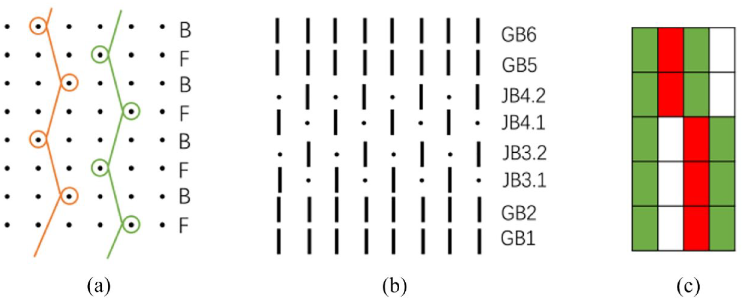
Knitting parameters of the warp-knitted double-needle bed creel jacquard fabric: (a) chain notation, (b) threading, and (c) jacquard pattern.
Basic chain notation model
The warp-knitted double-needle bed creel jacquard fabric is knitted by ground guide bars and jacquard guide bars. Generally speaking, each complete jacquard guide bar consists of two half-gage jacquard guide bars. They are represented by the same lateral movement line and the yarns on them have the same basic chain notation as shown in Figure 1(a). “F” represents the needle on the front bed while “B” is represents the needle on the back bed. The green yarn shows the basic structure of the jacquard bar on the front needle bed, because the stitches are only knitted on the front-bed needles. The orange yarn describes the basic structure of the jacquard bar on the back needle bed. The yarn only forms the stitches on the back bed needles. Each two rows of stitches on the chain notation bitmap, including one stitch on the front-bed needle and one stitch on the back bed needle, form one course. Each course has a set of four notation numbers, which controls yarns lapping in the needles from the fabric bottom to the fabric top. In each set of notation numbers, the first and the second numbers express the guide needle move horizontally on the front needle bed, while the third and fourth numbers indicate that the guide needle moves horizontally on the back needle bed. Therefore, a matrix

Where,
Combining the decomposition form of the chain notation for each course, a complete chain notation for one guide bar can be formed. The matrix is as follow:

Where,
Threading model
Threading is the yarn arrangement of each lateral movement line, which is an important parameter for pattern design. Due to the fact that the shogging mechanism of the warp knitting machine is generally located on the right side of the machine, yarns are arranged from right to left on the machine. So in the threading regular, the symbols are also designed from right to left as shown in Figure 1(b). The small dot represents that there is no yarn in this guide needle and the small line shows that the yarn is threaded in the guide needle. The color and width of the small line vary with the color and thickness of the yarn. Thus, the yarn type, thickness need to be included in the threading model as shown in Formula (3).

However, since yarn information is not directly involved in the parameter calculation of the warp-knitted double-needle bed creel jacquard fabric, the information whether threading or not is expressed separately using the Formula (4)

Where,

Where,
By combining the threading information of each yarn with the full pattern width and the full pattern height, a complete threading matrix can be formed, as follows:
Where,
Similarly,


The full threading position with the full pattern width and the full pattern height is shown in Formula (9):

Jacquard displacement signal model
Figure 1(c) illustrates the jacquard design pattern, and the pattern of the double-needle bed warp-knitted jacquard fabric is controlled by the displacement information of the jacquard design grid. Each jacquard grid represents a pattern unit comprising two knitting cycles, where the jacquard guide needles complete two rounds of stitch formation successively on the front and back needle beds. Each round of stitch formation consists of overlap displacement and underlap displacement, controlled by two displacement signals respectively.
Figure 2 shows the control information contained in a jacquard grid, with a total of eight displacement signals. Each two displacement signals represent the displacement information of one course. A and B represent the overlap and underlap displacement of the odd courses of the front needle bed, C and D represent the overlap and underlap displacement of the odd courses of the back needle bed, E and F represent the even course displacement of the front needle bed, G and H represent the even course displacement of the back needle bed. In jacquard control technology, the letters H and T are used to indicate the offset status of the lateral movement information, where H indicates that the guide needle doesn’t displace and T indicates that the guide needle displaces to the left. Taking the jacquard signals of the front bed for example, when the lapping displacement keeps the same in both odd and even courses, the displacement signal of the jacquard grid is HHHH-HHHH. When the lapping displacement of the odd course remains unchanged while that of the even course move one needle to the left, the displacement signal of the jacquard grid is HHHH-TTHH. Another situation is, the lapping displacement of the even course keeps the same but that of the odd course is offset by one needle position to the left, the displacement signals is TTHH-HHHH.
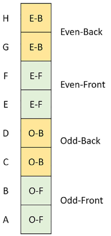
Control information in a jacquard grid with eight signals.
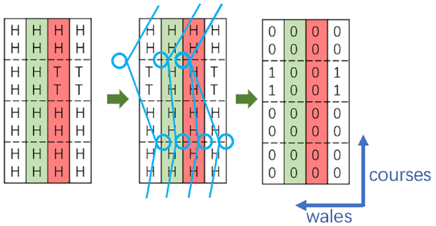
In actual knitting, the lapping effect doesn’t keep consistent with the designed pattern because the effect of jacquard needle lags behind one wale at the even course, which is recorded as RT = 0 (RT is raschel technology parameter). In order to knit the fabric matching with the jacquard bitmap, the displacement signals of the even course need to be shifted to the right by one wale as shown in Figure 3(a), which is defined as RT = 1. In Figure 3(b), the displacement signals are converted to the digital information where H is recorded as 0 and T is recorded as 1. The warp knitted fabric is knitted from the right-bottom, so the displacement signal is added to the displacement signal matrix one by one starting from the right-bottom corner. And every two columns in the matrix represent the displacement signal in one wale, whose format is consistent with the chain notation matrix.
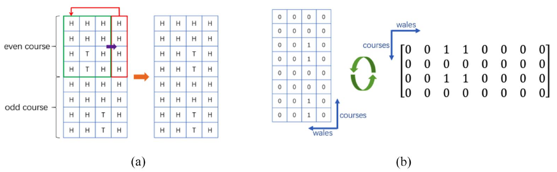
Displacement signals of the jacquard pattern: (a) displacement signal correction and (b) displacement signal matrix.
Generally speaking, two half-gage jacquard bar of the warp-knitted double-needle bed creel jacquard fabric knit the different pattern on the front and back needle beds. Therefore, the jacquard pattern bitmaps of them are designed respectively. The displacement matrix of these two half-gage jacquard bars based on the displacement signals are established as follows:
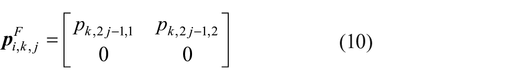

Where,
For the ground bar, the chain notation is independent that is not affected by the jacquard information, so the displacement matrix element value is 0. The matrix of the ground bar is Formula (12).

In summary, the displacement matrices of each lateral movement lines

Where,
Parameter model combination
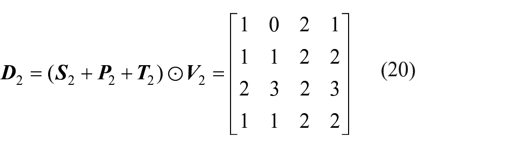
In the above, mathematical matrices for the chain notation, threading and jacquard displacement signal are established. By superposing the basic chain notion matrix


Where,
Taking the jacquard pattern in Figure 4 for example. The jacquard bar is at the second lateral movement line and the basic chain notation is 1-0-1-1/1-2-1-1//. Figure 4 shows the displacement signals of two middle wales. Thus, the chain notation matrix


An example for illustration of the mathematical models.
Geometric modelling of fabric layers
The warp-knitted double-needle bed creel jacquard fabric has a sandwich structure that is divided into a front piece of fabric, a back piece of fabric and a spacer yarn layer. For the warp-knitted double-needle bed spacer fabric, only the spacer yarns are knitted both on the front fabric and the back fabric. And if the fabric has jacquard structures, the pattern is only knitted on the front fabric. But it is different for the creel jacquard fabric. The yarns on the jacquard bars are provided independently by the bobbins on the creels so that the jacquard yarns can be knitted on the front and the back fabrics flexibly. It can also knit spacer layers. The jacquard patterns are distributed in different regions on the one side fabric face. Figure 5 shows a warp-knitted double-needle bed creel jacquard fabric. Seen from the side view, the front fabric piece and the back fabric piece locate on both sides while the spacer yarns are in the middle. The fabric pieces on both sides also have layers, where the stitch layers are on the outside and the underlap layers are on the inside. And the jacquard patterns can be seen both on the front side and the back side, which makes the fabric more neat beautiful.

The real structure of the warp-knitted double-needle bed creel jacquard fabric.
Formula (15) is the final chain notation of each lateral movement line, and the stitch types can be derived as Formula (21) shows.

Where,
The values of
Dividing the fabric from the spacer layer, the layer regular of each fabric piece is analyzed and their own layer models for stitches and underlaps are established.
Stitch face layer
Since the underlaps are different, the stitch number bent by yarns is also different. The stitch quantity on the single wale can be calculated by Formula (22) with round down method.

Where,
In order to establish the stitch layer model, the right side of the stitch on the first wale of the first yarn when the first lateral movement line is defined as the start needle position. Thus, the needle position of the right side of the i-th lateral movement line, the k-th yarn and the j-th course stitch is calculated as Formula (23).

Where,
For the warp knitted fabric, the stitches of one yarn are not always on the same wale. According to the chain notation, some stitches will exceed the pattern width. As we can see in Figure 6, some stitches of the right yarns are located at the right side of the pattern width range while some stitches of the left yarns lie beyond the w-th needle. However, because yarns are arranged circularly in the fabric in units of one pattern width, stitches beyond the pattern width, actually, are located on the former pattern circle (the right stitches) or the next patter circle (the left stitches). Therefore, the stitch position needs to be converted within a pattern width so that a single pattern width can cover all stitches. The converted stitch position n is shown in Formula (24).
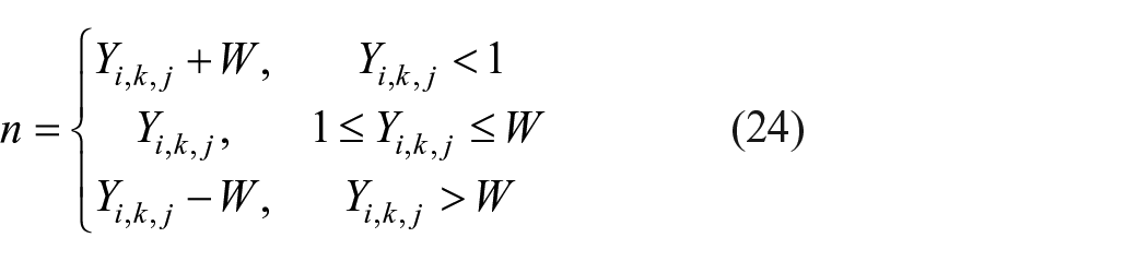
Where, n is the stitch position on the course in one pattern circle, W is the pattern width,
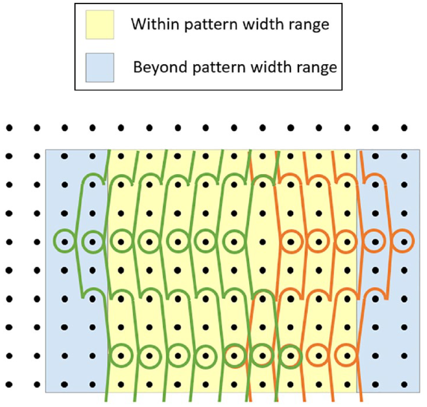
Stitch position on the fabric with one threading circle.
When the stitch position is determined, the stitch number of each yarn on the n-th wale

Where,
For example, supposing that the warp-knitting structure is arranged from the front needle bed to the back needle bed. For the warp-knitted double-needle bed creel jacquard fabric, normally it has a maximum of 10 lateral movement lines. And each lateral movement line can knit on the both sides. One stitch has two layers including one stitch face layer and underlap layer. If the stitches of each lateral movement line are on the different layer without overlapping, one fabric side may have 20 layers. Thus, for the double sides, it will have 40 layers in maximum. So 40 layers are reserved in the layer model, containing all levels of possibilities. As shown in Figure 7(a), the stitch layers of the front needle bed are in layers 1–10, and the underlap layers are in layers 11–20; on the back needle bed, the underlap layers are in layers 21–30, and the stitch layers are in layers 31–40. Yet it should be noted that for the two-needle stitch type, the first stitch is always on the upper layer compared to the other stitch. That means, the second stitch is always under the first stitch of the next yarn on the same wale. And due to the interlocking structure of the knitted fabric, the stitch arc and pillars are not in the same layer as Figure 7(b) shows. In the same stitch, the stitch bottom is always at the outer layer relative to the stitch arc. So layers of the stitch arc and the stitch pillar are calculated respectively as follows:


Where,

An example for the layered structure: (a) layer distribution and (b) layer details for stitch interlocking.
Underlap layer
The underlap is divided into three types in the warp-knitted double-needle bed creel jacquard fabric: underlaps only on the front needle bed, only on the back needle bed and spacer yarns. The underlap values of these yarns can be represented as Formula (28).

Where,
Formula (29) shows the stitch arrangement of the i-th lateral movement line on each needle bed, which is derived from the stitch types in the same yarn.

Where,
Make
Thus, the underlap layer can be determined as Formula (30) shows.

However, not all the fabrics can occupy 40 layers, resulting in some layers without yarns. So the layer distribution needs to be reordered from the first layer, removing the empty layer.
3d simulation implementation and results
Fabric samples
Taking a fabric for example as shown in Figure 8(a). It is a shoe upper knitted on an E24 RDPJ6/1 with the pattern size of 240 wales and 360 courses. The fabric knitting density is 13.5 cpc and 25.4 wpc. The fabric is designed in WKCAD 4.3, including the basic parameters as shown in Table 1 (the basic chain notation, the threading, the jacquard pattern, materials) and other knitting information such as machine type, knitting gage and so on. The fabric jacquard pattern is also designed in WKCAD 4.3 shown in Figure 8(b), which determines the final yarn lappings of the fabric. The left one is the full jacquard pattern, containing the displacement signals on the front, back and front to back or back to front needle bed. Different colors represent different signals. The right one is the front pattern effect, which separates the displacement signals of the front needle bed, resulting in a clearer pattern effect. And Figure 8(c) is the simulation result.

The whole fabric for the shoe upper: (a) real fabric, (b) jacquard pattern, and (c) simulation result.
Fabric knitting parameters designed in WKCAD 4.3.

Simulation details
To test the mathematical models established above, a program is designed by C++ for 3D simulation. The total simulation process is step-by-step and the executive process is shown in Figure 9. The modeling of the knitting parameters and the yarn layers is the second and third steps which are described in detail. Besides, it is necessary for generation of the stitch modeling using geometry tubes. The stitch shape is decided by the real stitch, referring to the previous research. 5 Thus, stitches are connected together on different layers to form the fabric.

Executive process.
Results and discussion
Figure 8 shows the real fabric and the simulation result of the whole shoe upper. The result gives an overall effect from the front view. In order to obtain a more detailed stitch layer arrangement, take one small piece of the fabric as an example (Figure 10) for explanation. Due to the fact that the pattern effect of the fabric is mainly based on the front fabric, the detailed analysis is mainly conducted on the front fabric pattern.

Detailed simulation result of a part of the fabric.
Figure 11 shows the simulation result and real fabric from the side view. The real fabric is hard to observe the yarns because some yarn materials have elastic property. But in the simulation result, the yarn layer is clear from layer 1–15. Spacer yarns form the front fabric to the back fabric do not occupy layers. And the distance of the spacer yarns can be changed for the better observation as needed.

Simulation results from the side view of the fabric.
Two half-gage jacquard bars (L4 and L5 in Table 1) are threaded by green and white yarns to form the main pattern. For the front fabric, stitches knitted by two jacquard bars are all at the outermost layer according to the layer calculation method proposed above. So as shown in Figure 12(a) and (b), stitches knitted by jacquard green and white yarn are on the on the superficial layer. In order to distinguish the yarn movement trend, the colors of some simulated yarns are changed as needed. The single stitches of the jacquard bar are interlocked with the stitch knitted by transparent fishing lines, so there is an interlaced sesame dot pattern in this area as shown in Figure 12(a). Figure 12(b) shows two-needle stitches structure. Two stitches in the same course are knitted by one yarn. And because of the threading parameter, one yarn threading and one yarn empty, the second stitch on the left side is not covered by the first stitch of the next yarn, so that both stitches of the two-needle stitch are all on the first layer.

Stitch simulation and layer distribution of jacquard bars: (a) single stitches knitted by the jacquard bar and (b) two-needle stitches knitted by the jacquard bar.
For the ground bar L3, the stitches interlocked with the jacquard stitches are formed by the transparent fishing line. The simulation results are shown in Figure 13(a). The transparent yarns are placed by the orange and the blue yarns, which are threaded one by one. Taking two yarns (the right blue yarn and the left orange yarn) for example. When there are only ground-bar stitches on the same needle position, and if the knitting direction is from the right to the left, the second blue stitch is covered by the first orange stitch. Also, it covers another second orange stitch of the right yarn. The first stitch is on the first layer while the second stitch is on the second layer. However, when there are both jacquard-bar stitches and ground-bar stitches on the same needle position as seen from the slant-side view, the jacquard stitches are on the first layer and the ground-bar stitches are on the second layer.
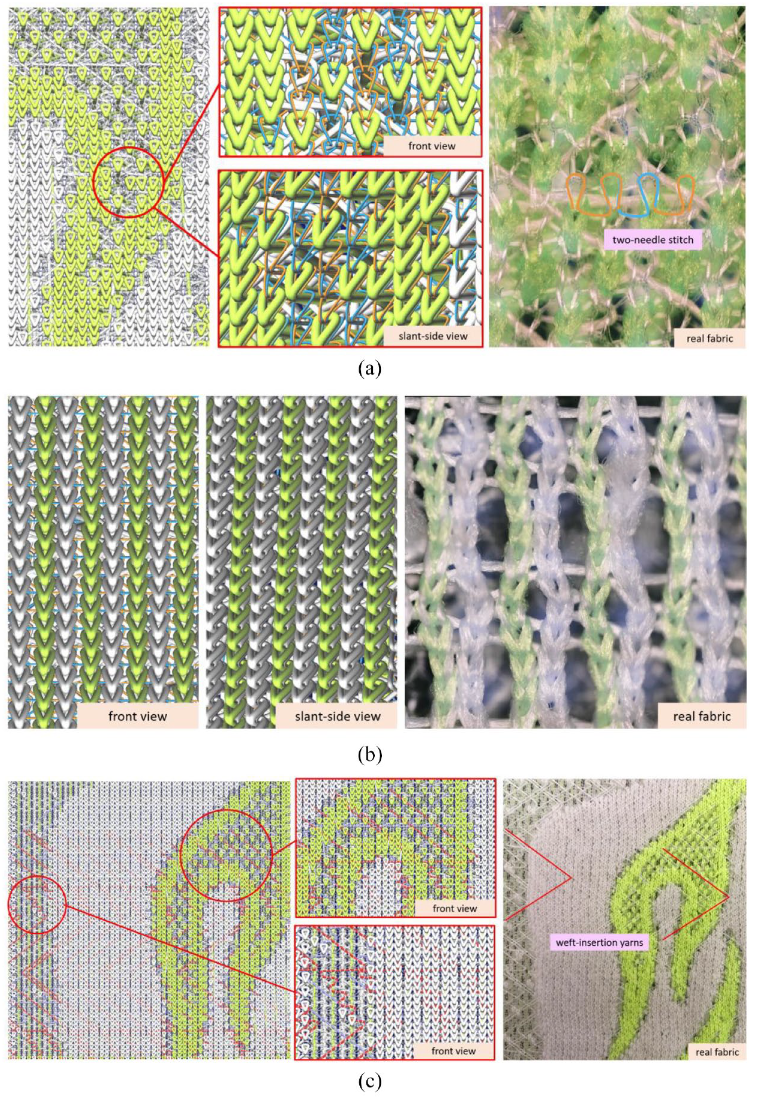
Stitch simulation and layer distribution of ground bars: (a) two-needle stitches knitted by ground bar, (b) single stitches knitted by ground bar, and (c) weft insertion yarns knitted by ground bar.
According to the knitting parameters in Table 1, the ground bars L6 and L7 are only knitted on the back needle bed, forming the back fabric as seen in Figure 13(b). In our simulation method, the deformation of the fabric is ignored so the stitches of the simulation result are vertical, different from the real fabric. If there are only ground stitches, they are arranged in the first and the second layer numbered from the back fabric. And if the ground stitch is overlaid with the jacquard stitch, the stitch is in the second layer of the back fabric. The actual layer in the whole fabric from the front fabric is the 14th and the 15th layers.
And the ground bar L1 and L2 knit the weft insertion yarns as shown in Figure 13(c). It is observed that the weft insertion yarns are knitted as red fold lines. The weft insertion yarns are held between the stitch body and the stitch underlaps of the front fabric, which lay in the fifth layer.
Therefore, the fabric layer model proposed above can effectively distinguish the layers of stitches, even if they are knitted by different bars.
Conclusion
A 3D simulation method is presented for the warp-knitted double-needle bed creel jacquard fabric based on the stitch layer. According to the knitting technology, mathematical models for basic parameters including the basic chain notation matrix
Footnotes
Declaration of conflicting interests
The author(s) declared no potential conflicts of interest with respect to the research, authorship, and/or publication of this article.
Funding
The author(s) disclosed receipt of the following financial support for the research, authorship, and/or publication of this article: The article is supported by the Natural Science Foundation of Jiangsu Province (BK20221094), Taihuzhiguang Science and Technology Research (fundamental research) Project of Wuxi (K20221007).