
Abstract
The comber is very important in the spinning for high quality yarns, in which the nipper mechanism (NM) determines the quality of the yarn it combs. This paper is to connect topology and multi-body dynamics to reveal the principle of impact motion of the nipper mechanism. Firstly, the working process of the NM is analyzed and corresponding kinematic models of work sub-phases are derived. Subsequently, the transition from the work phase of the jaw closed to the opened is studied. The research results show that during the transformation process, the mechanism presented another work phase with multiple impacts, which is the main reason why the NM could not stably clamp the cotton clump and thus affect the quality of the yarn combed by the comber. According to the relative coordinate method, the dynamic model of the NM is set up. Combining the classical collision theory and the restitution coefficient equation, the acquisition of the impact impulse generated at the jaw and the subsequent motion of the mechanism are decided. Finally, the NM in the E62 comber is taken as an example to verify the correctness of the established dynamic model, and the influences of different input speeds, restitution coefficients, and stiffness coefficients of spring on the jaw’s impact are studied. This has certain theoretical value for improving the speed and efficiency of the comber.
Introduction
With the rapid development of human society and the progress of science and technology, people’s living standards continue to improve. The demand for high-grade textiles and special textiles is increasingly large. Without the combing process, it is difficult to meet the manufacturing requirements of yarn below 9.7tex which is used in the production of high-grade fabric and special fabric, such as medical suture thread, tire cord thread, high-speed sewing thread, and embroidery thread. 1 Therefore, the comber is the key equipment to produce yarn with high quality, in which the short fiber, neps, and impurities could be removed and cotton fibers can be straightened. 2
Comber is mainly composed of five parts the nipper system, separating roller mechanism, feeding mechanism, top combing mechanism, and cylinder mechanism, among which the nipper system plays the most important role in the combing process with achieving complex motion including the jaw’s opening-closing motion and the nippers’ reciprocating swing motion. And meanwhile, the nipper mechanism (NM) in the system is the main part to produce noise and vibration. 3 Therefore, the research on it has been attracting great attention. Zhao et al.4,5 studied the low order resonance phenomenon of NMs based on the kineto-elasto-dynamics (KED) and established a nonlinear dynamic model suitable for the mechanism. Li et al. 6 analyzed the carding force, separate drafting force, inertia force of the NM, and inertia force of the nipper pendulum shaft and investigated their relationships with the driving torque of the nipper pendulum shaft. Su et al. 7 discussed the research on optimization of the nipper mechanism on CM500 series Combers and addressed the corresponding optimal crank radius. Liang et al. 8 studied the stress and deformation on the working state of the bottom nipper in the comber and analyzed the dynamics of the nipper clamping process. But up till now, the dynamic model of NM considering the jaw’s impact and collision has not been established yet because the effective number of links and joints changed a few times during the working process.
As a high-speed mechanism, the quality of the yarn is greatly affected by the impact generated by NM during operation. Therefore, it is necessary to study the principles of impact and strategies for reducing impact. Li et al. 9 proposed a deployable truss with multiple configurations and gave the optimal deploying-sequence scheme of the mechanism to minimize the deployment impact. Yang et al. 10 proposed a reliability optimization design method for the stability of configuration transformation of constrained metamorphic mechanisms and optimized the tolerances of random variables of structural parameters. Song et al. 11 proposed two performance indices to quantitatively study how dynamic parameters such as mass, inertia, and stiffness affect the impact force reduction capability and maximum safe speed. Konno et al. 12 adopted sequential quadratic programming to solve a non-linear programming problem in the impact motion generated in humanoid robots. For multi-body systems considering impact, another urgent issue that needs to be addressed is the analysis of the motion reliability. For this, Wu et al. 13 proposed a method to evaluate the mechanism reliability of the bistable compliant mechanism considering degradation and uncertainties of the parameters. Wang et al. 14 proposed a reliability analysis of dynamics for a controllable metamorphic palletizing robot considering the multiple failure modes and the random and interval variables. To address the low computational efficiency and accuracy for reliability optimization of flexible mechanisms, Bai et al. 15 proposed the mean-probability decomposition-coordination-based extreme support vector machine regression method based on the dynamics and uncertainty.
The impact problem caused in the NM belongs to the category of internal collision of multi-body systems, and a large number of novel and useful research results now have been achieved in this field. For the case of rigid impact, Hurmuzlu et al. 16 developed two solution procedures that cast the impact equations in differential and algebraic forms are developed to solve the rigid body collisions of planar kinematic chains with multiple contact points, and elaborated on the rebounds at the noncolliding ends. Zahedi and Mata et al.17,18 presented a method for solving the complete dynamic problem of multi-closed-loop mechanisms based on the Gibbs-Appell (G-A) and the Newton’s impact formulas. For the contact-impact problems of flexible multi-body systems, Shafei et al. 19 investigated the effects of the mode shapes on the temporal response of these types of mechanical systems according to the Timoshenko beam theory and the assumed modes method. Chen et al. 20 presented a formulation based on the combination of the component mode synthesis method and the Lagrangian method. Dong et al. 21 proposed a calculation method for collision dynamic model of flexible multi-body system based on variable topology theory by combining the floating coordinate method with the finite element method. Korayem et al. 22 investigated the dynamic equations of an N-flexible link manipulator with revolute–prismatic joints via the Gibbs–Appell equations. For collision problems with friction considered, Natsiavas et al. 23 proposed a numerical integration method for determining the dynamics of a class of multibody systems. Ahmadizadeh et al. 24 developed a special computational algorithm to solve the dynamic model in which the contact force model is employed for modeling the impact-contact phenomenon. Shafei and Ahmadizadeh et al.25,26 studied the multiple impacts of robotic systems, and derived the dynamic equations of motion for such systems by the Gibbs-Appell recursive algorithm and regularized method. Stronge 27 employed two impact parameters to treat terminal velocities and energy dissipation as functions of the normalized angle of incidence in the case of oblique planar impact.
Although impact problems can be divided into various situations, as mentioned above such as considering rigidity, flexibility, friction, and studying the stability and reliability of mechanism operating, the means to analyze these situations all involve the establishment of dynamic models. At present, the commonly used methods for analyzing the dynamics of impact systems can be classified as: Kane’s method,28,29 Newton-Euler method,30-32 D’Alembert’s principle, 33 Lagrange method,34-37 Gibbs-Appell (G-A) methodology,38-41 and analytical algorithm. 42 These methods have different modeling processes for motion equations, but the results obtained are similar. However, the difference from other studied objects is that the NM in the comber has two working phases, and the topological structure of the mechanism is inconsistent in both phases. The change in topology is caused by both force and position constraints, while the impact is generated during this changing process. Accordingly, the best strategy for dynamic analysis of the mechanism is to introduce a mathematic model that can reflect this topological change to disclose such phenomena, thereby minimizing the detrimental effects resulting from the impact. In this study, the working principle of the NM is analyzed based on the topological principle, and corresponding kinematic models are set up. According to the investigation of work sub-phases for the NM, the movement status of the NM during the process from jaw opening to stable closing is identified, and the third working phase that occurred in this process is defined. The research on the impact motion of this mechanism is based on the relative coordinate method, which uses graph theory to describe the structural characteristics and connection relationships between various bodies, reflecting effectively the changes in topological structure when the working sub-phases transform. Lastly, taking the NM in E62 comber as an example, influences of input speeds, restitution coefficients, and stiffness coefficients of spring on the jaw’s impact are researched, and some conclusions that contribute greatly to mechanical design are obtained.
Working principle of the nipper system
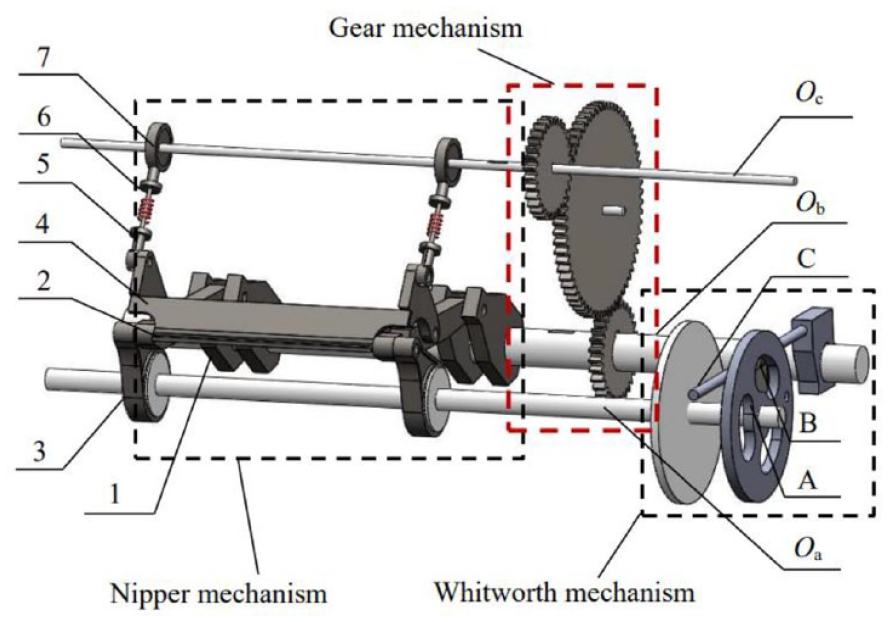
As shown in Figure 1, the nipper system is composed of the Whitworth mechanism, gear mechanism, and nipper mechanism. The system adopts a single driving scheme to satisfy 2 degrees of freedom (DOFs). Specifically, the cylinder shaft is driven by an electromotor and its rotation can be transmitted to the nipper pendulum shaft and tension shaft by the Whitworth mechanism and gear mechanism. When the cylinder shaft rotates one circle, the nipper pendulum shaft swings back and forth once and the jaw is opened and closed once, which is a complete working cycle of the NM. There are therefore two work phases in one cycle
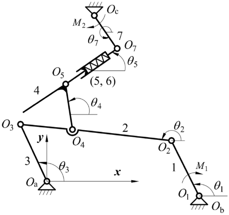
Mechanical model of the nipper system.

Work phase 1 of the NM: (a) three-dimensional graph and (b) structural diagram.

Work phase 2 of the NM: (a) three-dimensional graph and (b) structural diagram.
The achievement of transformation from phase 1 to phase 2 relies on the combination of the force and position constraints as shown in Figure 4, the compressed spring is installed between links 5 and 6. Where

The structure of steeve in NM.
Kinematic analysis of the nipper system
Whitworth mechanism
The structural diagram of the Whitworth mechanisms is shown in Figure 5. Let

Structural diagram of the Whitworth mechanism.
For this mechanism, the closed-loop vector equation is established in the form

Where

Where
Nipper mechanism
The stable operation process of the NM consists of two phases in one work cycle. In phase 1 as shown in Figure 6, links 5 and 6 are treated as one link (5, 6). Let
Structural diagram of the NM in phase 1.
Since links C and 1 are fixed on the nipper pendulum shaft, the angle

Where
As for links 1, 2, 3, and frame, the corresponding closed-loop vector equation is established as

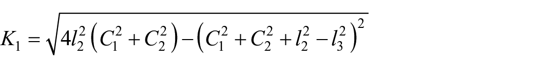
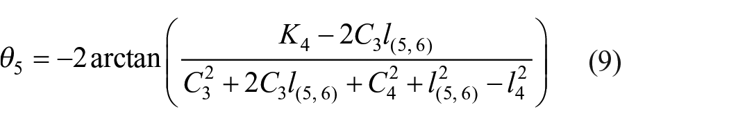
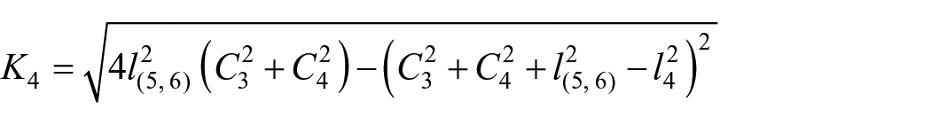
Where symbols represent the vector expressions for corresponding links. According to equation (4), the angle


Where
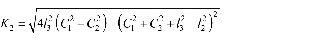


Similarly, the closed-loop vector equation of another loop in the mechanism is

Where


Where
Because the tension shaft and nipper pendulum shaft are connected by a gear train, the angle
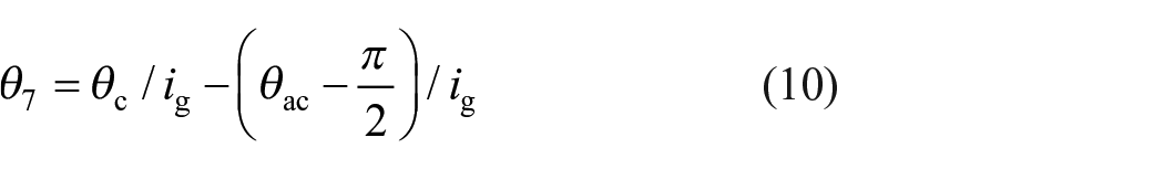
Where ig is the transmission ratio of the gear mechanism.
Figure 7 shows the structural diagram of the NM in phase 2. In this state, links 2 and 4 are considered as one link (2, 4), link 6 moves relative to link 5 and the slid distance is s,

Structural diagram of the NM in phase 2.
Other angles are similar to that in phase 1, while angles


Where
Dynamic analysis of the Nm considering jaw’s impact
System description
Due to the collision and impact generated during work phase transforming, the transformation process will take some time rather than complete immediately. This study proposes a dynamic modeling method to describe and analyze the corresponding complex motion that existed in the process. When the top nipper contacts with the bottom nipper, they will move in the opposite direction because of impact. Meanwhile, the spring will be compressed further and then recover gradually, which causes a variation in the length of the steeve. At this point, the mechanism presents a different structural topology compared with phases 1 and 2, and is defined as phase 3. The mechanism in this phase is a 3-DOF eight-bar planar linkage with revolute and prismatic joints. Its additional DOF is driven by the spring, as shown in Figure 8.

The topological structure of the phase 3: (a) three-dimensional graph and (b) structural diagram
The phase 3 is a closed-loop system with two loops. To facilitate the establishment of its dynamic model, two joints need to be cut off to reduce it to an open-loop system according to the reducing method, 43 as shown in Figure 9, in which link 0 is the frame.
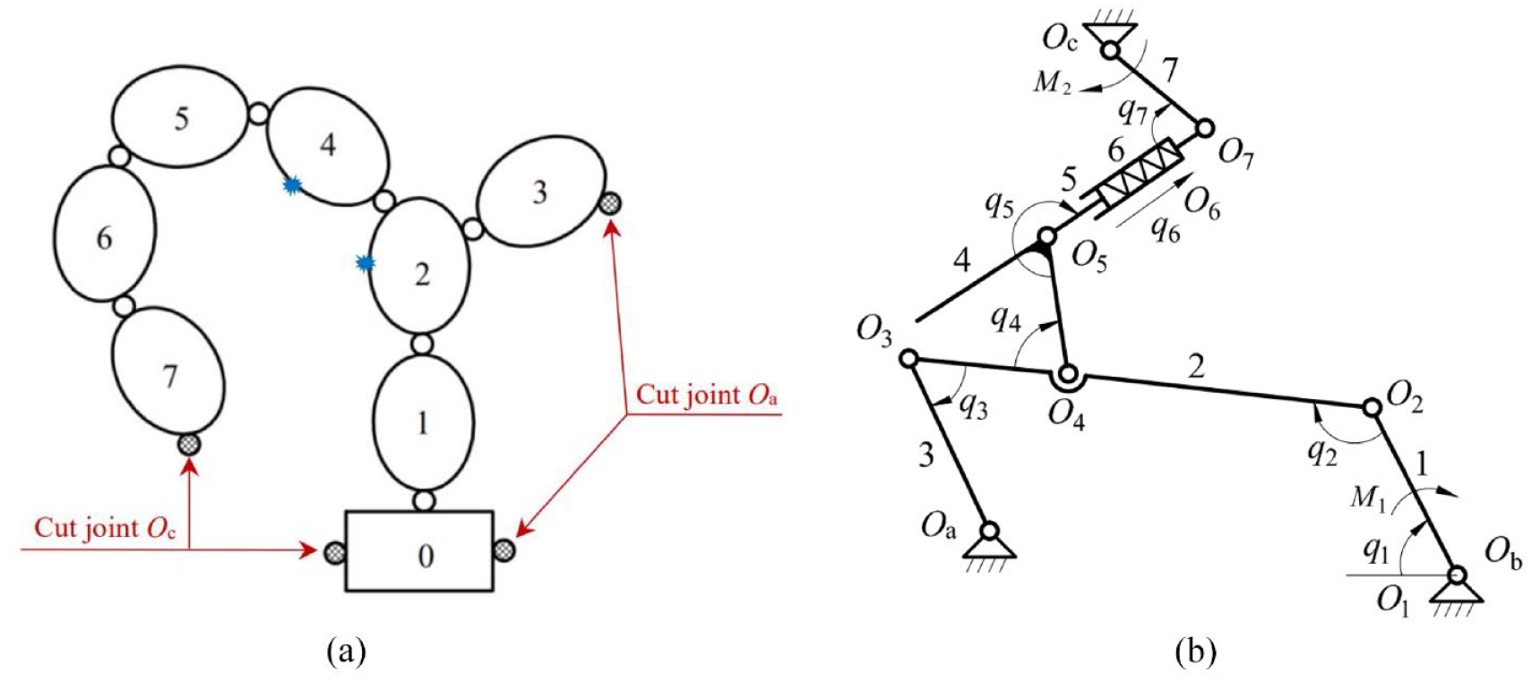
The phase 3 mechanism and its reduced system: (a) the reduced system and (b) the kinematic diagram of the phase 3.
Suppose the relative movements between adjacent links, shown in Figure 9(b), are selected as the generalized coordinates of the system, so the generalized coordinate vector is

Dynamics analysis
In order to produce an equivalence in dynamics after cutting two joints compared to before that, four constraint equations should be introduced. Let them be written in a matrix form

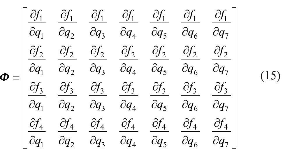
Where
Ignoring the influence of external disturbance such as friction, the dynamic equation of the phase 3 can be written by the relative coordinate method as a matrix form 44

Where
Let the collision force generated between top and bottom nippers at the contact point be

Where
Assuming the shape, position, and orientation of every link and the external forces applied remain unchanged during colliding, because

Where

On the other hand, increments in the angular velocity and the centroid velocity as well as the increments in velocities of top and bottom nippers at the impact point after colliding can be obtained


Where
Substituting equation (18), (20), and (21) into equation (22), the relationship between the difference in velocity increments as shown in equation (22) and the impact impulse can be established

Where

According to the relevant theory of linear algebra, it can be proved that the matrix

Where

Therefore, the centroid velocity and angular velocity of each link at the moment of the collision ending, or calling them velocities after colliding, can be deduced by substituting equations (25) and (18) into equations (20) and (21)

Where
Running of the Nm during Phase 3
Let the contact between top nipper and bottom nipper at the beginning of the process form phase 1 transforming to phase 2 be recorded as the first collision. After that, the NM transforms from phase 1 into phase3. Subsequently, it operates continuously to the second collision under the effects of spring and driving forces. Let the operation process be named the first operation of the phase 3, in which the motion state after the first collision is taken as the initial motion state of phase 3, and the final motion of its first operation is treated as the initial motion of the second collision. Consequently, during the transformation from phase 1 to phase 2, the motion of NM can be divided into two running stages.
Assuming the transformation of the work phase occurs at time

Where collision sequence p is a positive integer starting from 1,
During the transformation from phase 1 to phase 2, the motion state values after the p-th collision are regarded as the initial state values of the p-th operation of the phase 3, and the final motion state values of its p-th operation are used as the initial motion state values of the next collision and so on until the relative velocity between top and bottom nippers reaches the preset threshold. At this time, it is believed that the NM has completed the transformation and entered the phase 2. This process can be analyzed through numerical simulation, as shown in Figure 10.
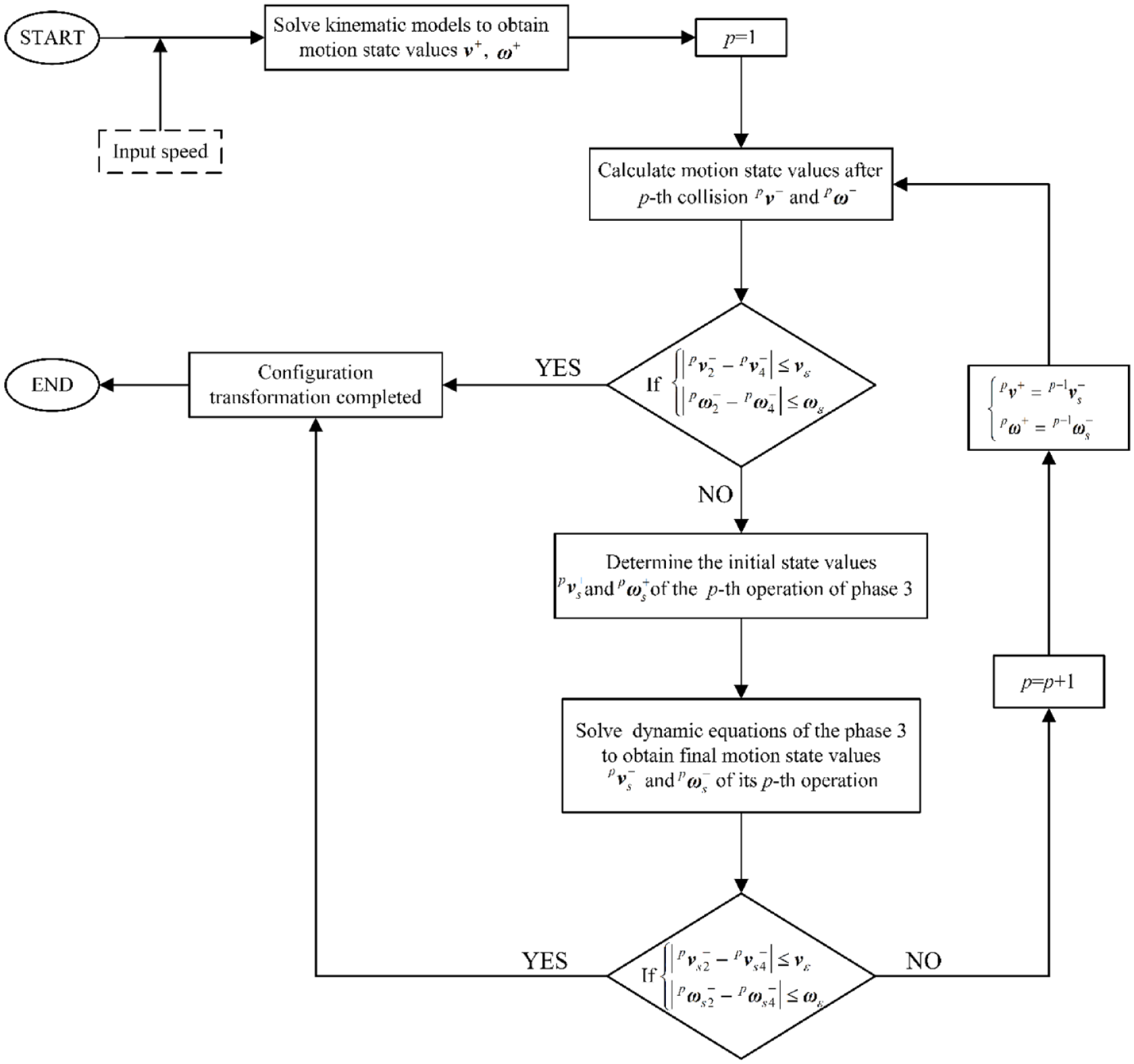
The flow chart of numerical simulation.
Research on impact characteristics
Taking the NM in E62 Comber as an example,
1
its virtual model is shown in Figure 1. The geometrical parameters and motion parameters are shown in Tables 1 and 2. The initial angular
Physical parameters of the NM.

Motion parameters of the NM for simulating.

The simulation time step is set to 0.01µ

Angular displacement of the jaw under different input speed: (a) 450 r/min, (b) 550 r/min, and (c) 650 r/min.
Figure 12 shows the impact impulse generated by each collision of the jaw at different speeds. It can be seen from the diagram that the impact impulse gradually decreases to 0 as the collision times increase, which is consistent with the trend of the jaw’s rebound and manifests that the rebound of the jaw is caused by impact. The higher the speed, the larger the impulse generated by per collision, resulting in more rebounds and collisions of the jaw, thereby extending the duration of work-phase transformation. When the impulse is 0, there is no force driving the jaw to rebound and the top nipper remains stationary relative to the bottom nipper and the transformation is finished. Therefore, to make the jaw clamp the cotton clump quickly and steadily, it is necessary to reduce the impact impulse generated by each collision.
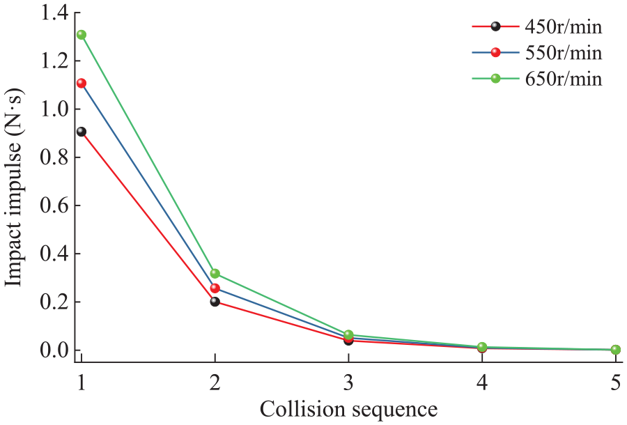
Impulse peaks of the jaw under different input speeds.
Another interesting phenomenon shown in Figures 11 and 12 is that the jaw rebounds significantly only in the first two times. The amplitude and time consumed for the first and second rebounds are shown in Table 3. Under three speeds, the times consumed by the first two rebounds account for 96.47%, 96.73%, and 96.75% of the times consumed for the process of work-phase transforming respectively. When the speed increases by 44.4%, the first rebound amplitude of the jaw increases by 118.4%, and the second increases by 113.6%, which indicated that the speed has an obvious influence on the impact motion of the jaw. Since the first two rebounds almost reflect all the motion characteristics of the jaw during transformation, we focus on these two rebounds in the following analysis.
Effect of different speeds on jaw’s impact motion.

Taking e = 0.05, 0.1, 0.15, 0.2, and 0.25 respectively to study further the influence of the restitution coefficient on jaw’s impact when input speed is 650 r/min and other conditions remain unchanged. The research results are shown in Table 4 and Figure 13, obviously, both convey an important conclusion that the restitution coefficient has a great influence on the impact motion of the jaw because the 4-fold increase in restitution coefficient results in a 19.8-fold increase in the amplitude of the first jaw’s rebound and a 551-fold increase in the second. In fact, when the variety of cotton clumps is changed, the flexibility is also different, resulting in a slight change in the restitution coefficient for the colliding between the top and bottom nippers. Although this change is minimal, it can also affect the jaw’s impact, causing unexpected vibrations. Besides, Figure 13 shows that the 4-fold increase in restitution coefficient leads to a 3.4-fold increase in the time consumed for work-phase transforming and a 3-fold increase in the number of collisions, which illustrates that the NM made from larger restitution coefficient materials takes more time to change its work phase and is more unstable during the period.
Effect of different restitution coefficients on jaw’s impact motion.

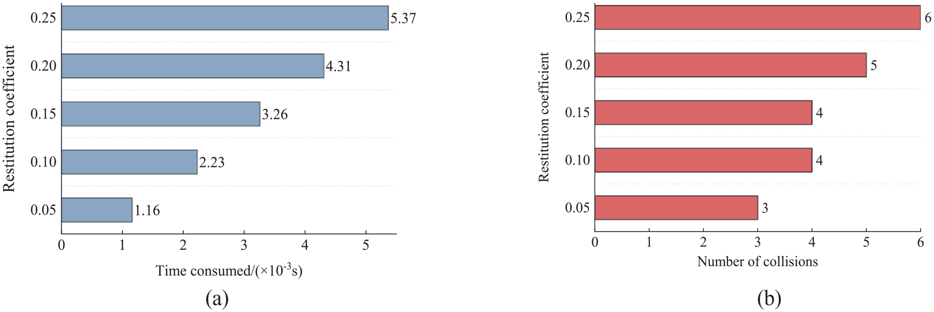
Effect of different restitution coefficients on (a) time consumed, (b) collision frequency during work-phase transformation.
To study the influence of spring stiffness on the jaw’s impact, the stiffness coefficients of 7, 8, 9, 10, and 11 are taken respectively with input speed 650 r/min and other conditions unchanged. As shown in Table 5 and Figure 14, when spring stiffness increases by 57.1%, the amplitudes of the first and second jaw’s rebound decrease by 31% and 30.2% respectively, and the time consumed decreases by 28.4% and 26.2%. Furthermore, the increase in spring stiffness has no obvious influence on the number of collisions between the top and bottom nippers during the transformation process, which suggests that a reasonable increase in spring stiffness will restrain the impact effect of the jaw.
Effect of different spring stiffness on jaw’s impact motion.

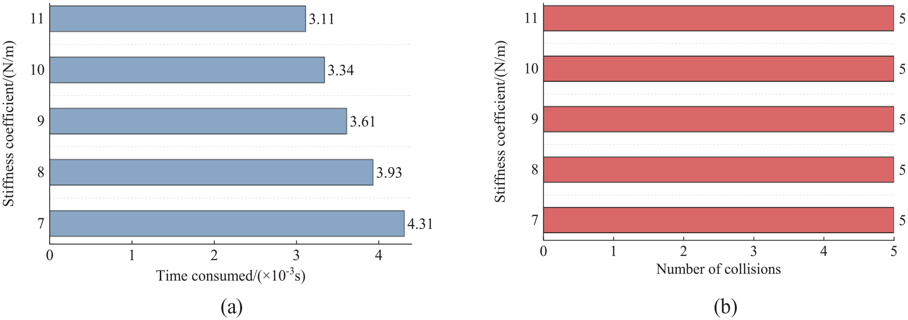
Effect of different stiffness coefficients of spring on (a) time consumed, (b) collision frequency during work-phase transformation.
From the aforementioned analytical results, there is a noteworthy point that the input speed and the restitution coefficient between the top and bottom nippers have greater effects on the jaw’s impact. In order to reduce the jaw’s impact, improve the stability and efficiency of the NM clamping the cotton clump and thus improve the combing quality of the comber, materials with large restitution coefficients should be avoided in the design stage to produce the top and bottom nippers, a lower speed input and larger stiffness coefficient of spring should be adopted within a reasonable range.
Conclusion
The impact generated by the NM during work-phase transformation has a great effect on the quality of the yarn combed by the comber. For that, this paper provides a method to analyze the effect of this impact on the stability and efficiency of NM. The traditional analysis method for the NM is to identify it as two working phases. However, this work considers the process of transforming from work phase 1 to phase 2, defining the third working phase of the NM, and analyzed the movement of the mechanism during this phase, pointing out that this movement process is essentially composed of two alternating movements. Based on the methods proposed in this paper, the NM in E62 comber is chosen as a specific example for analyzing its impact dynamic characteristics, and the effects of rotating speed, restitution coefficient, and spring stiffness on work-phase transformation are analyzed. The research results imply that a higher speed and larger restitution coefficient prolong the time consumed by transforming process and exacerbate instability in clamping cotton clumps, the increase of such two parameters will intensify the jaw’s impact effect, while an increase in spring stiffness within a reasonable range will dilute the impact. This work provides certain theoretical guidance for the optimization design and stability analysis of combers.
Footnotes
Declaration of conflicting interests
The author(s) declared no potential conflicts of interest with respect to the research, authorship, and/or publication of this article.
Funding
The author(s) disclosed receipt of the following financial support for the research, authorship, and/or publication of this article: This study was supported by the National Natural Science Foundation of China (No. 52005368, 52175243).