
Abstract
The Fourth Industrial Revolution conceptualizes the rapid change of industries resulting from the convergence of technologies such as artificial intelligence, genetic editing, and advanced robotics that enable increasing interconnectivity and machines that can analyze and diagnosing problems without human intervention, through intelligent automation. In this scenario, the use of augmented reality technologies is of great interest. The paper aims to explore the use of augmented reality in support of traditional inspections for assisting textile experts in fabric defect detection. The contribution of this study consists of three main phases, necessary for the future development of the system: (1) the analysis of possible automatic defect detection techniques; (2) the analysis of hardware solutions for the realization of a system based on important criteria such as operator comfort, system footprint, and so on; (3) the proposal of a possible comprehensive solution. Considering these aspects this paper identifies and investigate the best scenario for the introduction of artificial intelligence and augmented reality technologies to help the operator in the detection of textile defects.
Introduction
The Fourth Industrial Revolution (4IR), or Industry 4.0, conceptualizes the rapid change of industries resulting from the convergence of technologies such as artificial intelligence, genetic editing and advanced robotics that enable increasing interconnectivity and machines that can analyze and diagnosing problems without human intervention, through intelligent automation.1 –3 With these revolutionary features, the principles of Industry 4.0 have become an essential requirement for the future survival and upgrading of industries.
In this scenario, the use of augmented reality (AR) technologies is of great interest. As widely recognized4,5 AR is a technology that provides an extra dimension to the real world by overlaying information such as text, images, and sounds on top of the world we see. This creates an interactive experience of an existing real environment that can be enhanced by inserting computer-generated images. AR can support Industry 4.0 in various stages, including product manufacturing, service and maintenance, logistics, sales and presales, job protection, and safety.
This paper aims to evaluate the feasibility of introducing AR technologies to support textile industries, specifically for the assisted detection of textile defects. To date, defect detection is based on the experience gained by operators rather than on technical and scientific analysis. Specifically, the defect inspection stage is generally performed by operators who, by visually and manually inspecting fabrics using dedicated machines (called “courts” or “mirror machines”), provide interpretations on the achieved finish degree and the presence of defects in the woven fabric. These machines typically consist of a vertical surface on which the fabric to be examined runs at different speeds. Such investigation is affected by inherent limitations of the method, such as the inconsistent performance in defect detection, the subjectivity of the investigation itself, and the limited volume of products that can be inspected per time unit. In recent years, several systems were proposed to solve this issue by leveraging machine learning, artificial vision and even Artificial Intelligence to automatically detect defects on fabrics running in mirror machines.6 –8 Despite such systems are becoming more and more efficient and reliable, their use is based on appositely devised systems “blind” to the textile expert and usually non-interoperable. For instance, because the automatic control device runs until the entire fabric is controlled, the operator is unable to intervene to fix a possible minor defect once it has been detected. Furthermore, the human expert is not allowed to physically mark the fabric, and this impacts on subsequent manufacturing processes such as the fabric cutting phase, which is required to exclude defective areas for creating the garments. More in general, the complete substitution of the operator with an automated machine would involve the implementation of completely new procedures for handling defective patches and for subsequent manufacturing.
Quite the reverse, the application of augmented reality systems in support (and not in substitution) of traditional inspection would improve the visibility of defects by creating a new inspection approach based on human-machine collaboration. These systems could have several advantages, including the potential to find defects that would otherwise go undetected due to a variety of factors, such as the operator being distracted or the defect being too small in size. Moreover, the inspection operation would be greatly facilitated, and the work made more bearable, thus providing positive effects on the workers’ well-being.
Compared with the realization of a fully automatic system, a hybrid system such as the one proposed in this paper, would be a product of easier distribution and easier introduction into the actual textile manufacture chain, when compared with complex fully automatic systems. In fact, the use of supporting technologies, instead of completely automated ones, can be introduced in the current practice without dramatically changing the inspection routine and, at the same time could provide a reliable support to operators.
To come with this issue, the main objective of this paper is a feasibility study of an AR-based hybrid system for defect control on textiles. The contribution of this study consists of three steps, necessary for the development of the system: (1) an overview of automatic defect detection techniques and the detailed examination of the most suitable technique; (2) the in-depth investigation of hardware solutions for the realization of the system, analyzing them according to important criteria such as operator comfort, system footprint and so on; (3) the proposal and analysis of a potential complete solution.
In fact, the authors’ perspective is that the initial phase of in-depth problem analysis is required for the successful implementation of the defect detection system based on augmented reality techniques in the future.
Materials and methods
Software solution analysis
According to the scientific literature, researchers have recently devised algorithms that can automate the process of fabric defect detection, allowing the textile industry to embrace the industry 4.0 trend. The most relevant algorithms for defect detection in fabrics can be roughly divided into two groups: deterministic image processing-based and machine learning-based algorithms. 9 Deterministic algorithms exploit feature extraction based on prior knowledge using statistical analysis methods, spectral analysis or with structural approaches of acquired images, or model-based. Approaches based on statistical analysis use the spatial distribution of gray levels present in the image, such as co-occurrence matrices (or also GLCMs – gray-level co-occurrence matrices), fractal dimension features, and pixel autocorrelation; in general, to determine whether or not a defect is present, extracted features are compared with features related to portions of the fabric that are considered correct and defect-free. 10 Referring to approaches for studying the spectrum, existing methods use a mathematical function that works by considering the image spectrum by transforming it, such as applying the Fourier transform, wavelet transform, Gabor transform, or discrete cosine transform, and then analyzing the result with thresholds, 11 or with a classifier. 12 In contrast, algorithms that exploit structural approaches are used to segment defective areas in fabrics where the image features a recurring pattern, such as the golden image subtraction (GIS) method and its wavelet GIS (WGIS) variant. 13 In general, all of these approaches subdivide the fabric into regions and by subtraction between similar regions identify possible defects. 9 Finally with regard to model-based methods these take advantage of the plots present on the fabric; these can be divided into regions and motifs from which features are extracted and using a specific model, for example, Gaussian mixture model, 14 Gabor filter bank, support vector data description model, or autoregressive spectral estimation model. 15 Such approaches are efficient in subdividing defective fabric regions from correct ones.
Algorithms based on deep learning, which do not require prior knowledge of the problem being addressed, are an alternative to deterministic algorithms. They are proved to be a very powerful tool capable of solving various types of segmentation and classification problems in many areas. For this type of algorithms, two main challenges have been identified: (i) AI training requires data to be collected on defective samples; (ii) real-time constraints required for high-speed online fabric analysis in a production scenario.
A class of algorithms is based on convolutional neural networks (CNNs), a special type of deep neural network that can directly process images, in particular from the basic structure of CNNs specific variants are created to detect defects in fabrics such as DCNN (Deep Convolutional Neural Network), EDDs (Efficient Defect Detectors), D4Net (De-Deformation Defect Detection network), 16 PRAN-Net (Priori Anchor Convolutional Neural Network). 17 These algorithms quite often meet real-time requirements and can run extremely quickly, but their accuracy isn’t always very high.
Other commonly used algorithms involve, for example, the use of networks, such as the Faster R-CNN, to identify regions of interest and then a CNN to classify them, 18 or Generative Adversarial Networks (GANs), which can automatically adapt to different types of fabric by directly learning the types of defects. 19 Other algorithms are based on the combination of features extracted by traditional algorithms and machine learning techniques, such as stacked convolutional autoencoders and CNNs. 20 This type of detector is usually able to achieve higher accuracy, but with a lower execution speed.
In general, the performance of a fabric inspection system is determined by many factors, and this falls back to choosing the best algorithm for each specific case. Such factors may be, for example, the contrast between defects and the texture, the image resolution, the image alignment and distortion, the defect size and shape, and the speed of the inspection system. In this paper, the main effort was to evaluate the most suitable algorithm to be used in an augmented reality context, considering a database of defects as generic as possible.
The accuracy of the method, the processing time, and the generalizability of the defect detection algorithm are the main constraints that come into play when analyzing the issue of being able to assist the operator in identifying defects with AR techniques. In effect, the inspection by the system has to take place during the unrolling of the fabric on the court that reaches speeds of about 0.5 m/s. On the other hand, the use of such a system truly gains value at the point when the system is upgradeable to detect new defects on new types of fabric rather than specializing on a single pattern.
As for traditional detection systems, only a few ensure real-time operation and with success rates that typically do not exceed 90%. In recent years, however, methods based on ML techniques have been proposed that allow real-time processing with good system accuracy. Methods based on ML techniques also have the potential to be more generalizable in that, for some models, to introduce a new fabric type it is usually sufficient to re-train the model on new images. This step would be much more complicated in the case of using traditional methods that are usually developed to detect a specific defect type or family of defects, on a specific pattern.
Following a screening of state-of-the-art work that aims at identifying defects on fabrics using ML techniques, among which Zhao et al. 21 and Dlamini et al. 22 stand out, it was decided to focus on the work proposed in Božič et al., 23 as, according to the authors, it is the most generalizable to different types of defects. To demonstrate this, the algorithm was used on a different dataset than the one originally proposed in the paper, namely on the Aitex Fabric Image Database (AFID).24,25 AFID contains 245 images of 7 different fabrics. In the dataset 140 images are defect-free, 20 for each type of fabric, the other 105 contain defects of different nature. The images are of size 4096 × 256 pixels. Figure 1 shows an example of two regions acquired from roll pieces with the corresponding ground truth.

Two images from the AFID dataset and the corresponding ground truth.
To test the method, given the size of the images, it was decided to divide them into patches. Patches were obtained by shifting a window of size 128 × 128 pixels in steps of 64 pixels. For model training and testing, all patches for which the mask did not indicate the presence of a defect were considered as the “undefective” sample, while the others were used as the “defective” sample. The dataset was divided into two main portions: one for training (70%) and one for testing (30%). The training set was further divided into two sets by k-fold cross-validation 26 (k = 10); the first for training the network and the second for identifying the best performing result. As for the final training and validation methodology, we used the functions implemented in Božič et al. 27 with the following parameters:
the weighted loss of this particular model was used, with a pos of 1 and a p of 2, which affect the contribution of the weight of the loss of a correctly classified sample;
weight for classification loss is set equal to 0.1;
a learning rate of 0.1, and a batch size of 1, for a total of 30 epochs, was carried out.
For a more detailed explanation of the different parameters, please refer to Božič et al. 23
The graph in Figure 2 shows some metrics taken into account during the training set while varying the number of epochs. These include the loss of the model, represented in blue, red, and orange, with the first two being the single loss of the two realized tasks (classification and segmentation), and in orange the weighted sum of the previous two losses, using the specified parameters. The green line represents the AP (Average Precision) relative to the validation set, used to select the epoch when the model achieved the best performance.

In blue red the single loss of the classification and segmentation tasks, in orange the weighted sum of the two losses. In green the relative to the validation set.
In the graphs shown in Figure 3 the results in terms of performance obtained on the testing set (30% of the cases previously removed from the original dataset) of the best solution identified can be seen. In particular, it can be noted how the model has an AUC (Area Under the Curve) that reaches 99.25%, an AP of 99.70%.
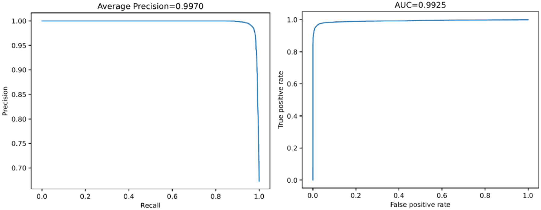
Resulting AP and AUC of the model.
Taking into consideration a threshold of 0.01344 (obtained heuristically by analyzing the f-score function) for deciding whether a sample is “defective” (minor) or “undefecive” (major), a classification accuracy of 97.30%, a true positive rate of 97.49% and a true negative rate of 96.90% were obtained. An example of three fabric patches with relative ground truth and the prediction made by the final model is shown in Figure 4.
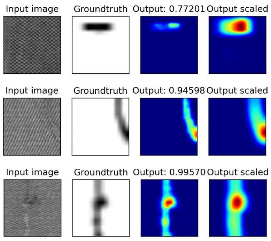
Example of defect detection on three fabric patches.
The time the network takes to analyze a patch is 2.65794 ms (±0.61681 ms, 99% CI), which makes the method suitable even for uses with restrictive speed requirements.
Hardware solution analysis
The main element to consider in evaluating the technical feasibility of the hardware infrastructure is the generation of an image set of sufficient quality to identify defects in a robust and reliable manner. This can be done by relying on existing textile defect datasets 24 on which defect identifiability was demonstrated in Section 2 of this study. In other words, the technical reliability of the solution is confirmed only when the ability to generate images of comparable quality to those of the datasets used can be confirmed, while maintaining the constraints imposed to ensure an industrially applicable technical solution. The resolution of the images and, in particular, the level of detail used to represent defects, serves as the primary criterion for this evaluation. This characteristic translates, essentially, into a certain number of pixels per unit length (i.e. px/mm). The Aitex 24 database offers images with a resolution of 4 px/mm and size of 4096 × 256 pixels. Similar databases, such as Refs.,27 –29 offer images with a resolution of 1 px/mm. Conservatively reasoning, this study considers achieving a resolution of 4 px/mm as the performance necessary for the system to function.
Another thing that must be considered when evaluating the technical feasibility of the image acquisition system for defect detection is the quality of the generated image. This is mainly determined by the type of illumination used, which heavily influences many of the individual aspects that help define the quality of an image (contrast, color accuracy, sharpness). In addition, there are some aspects that are directly attributable to the lenses used in the acquisition setup and therefore must be evaluated when choosing which lens to use; these include the generation of flare and artifacts and, even more so, the optical distortion introduced by the lens. This is more present on wide-angle optics, while it is reduced by choosing lenses with longer focal lengths.
Finally, the last thing to consider is the acquisition framerate, which need to be sufficiently high to avoid the acquisition of blurred images; the maximum acquisition framerate depends on two factors: a sufficient luminous intensity which in turn allows a reduced acquisition time to obtain a correct exposition, and the electromechanical hardware used in the acquisition system.
Considering the type of equipment and motion involved in fabric inspection, a camera equipped with a linear sensor is the most suitable for image acquisition. Such cameras provide a narrow field of view and a high framerate, making them ideal for observing continuous products like textiles. Line scan cameras, in particular, are commonly used in industrial processes to inspect fabrics. By aligning the line observed by the camera with the direction of fabric movement and synchronizing the acquisition framerate, it is possible to generate a complete image of the fabric similar to those used in the previous section. Notably, the images in database 24 were obtained using this setup, further confirming its feasibility for industrial fabric inspection.
Camera choice
Table 1 reports some of the linear scanning camera models that were surveyed from the literature. For the particular application, the main characteristics to take into account are resolution and acquisition spectrum (color/mono). Table 1 is focused on models characterized by a monochromatic acquisition spectrum. For many of the cameras shown in the table there are corresponding models with color acquisition spectrum, characterized by the same resolution. For the application under consideration, only monochrome cameras were considered given the characteristics of the databases used for testing.
Specifications of some linear scanning cameras surveyed from the literature.

As an example, the list of models produced by Teledyne DALSA, specifically the “Linea” products, is given in Table 2. Color and mono cameras are characterized by slight changes in the maximum framerate acquisition. For the specific application, as discussed below, too high framerates are not necessary; therefore, it remains open to realize the same setup with a color camera in order to inspect even defects in the fabric coloration (which, however, remain partly detectable even with mono cameras).
Teledyne Dalsa line scan cameras.

At this point, the choice of the specific configuration to be used can be made to guarantee the desired image resolution of 4 px/mm. Although fabric can come in a variety of sizes, a height of 2 m can generally be regarded as standard. Having 4K-pixel or 8K-pixel linear cameras available (some models on the market also offer 16K pixels, at even lower and therefore unacceptable framerates), it is possible to cover length of 1 and 2 m, respectively. The design of the acquisition device may then take this length value into account as the horizontal field of view (FOV) to be covered, and a pair of values (focal length of the optics/acquisition distance) may, therefore, be chosen such that this type of framed field of view is guaranteed. Table 3 shows the necessary acquisition distances, fitting optics with various focal lengths (35/55/85/105/200 mm) to obtain a FOV of desired length. Often, the lenses are defined by the degree of magnification, a characteristic that describes the same type of effect, that is what portion of the subject is framed within the FOV of the camera. Therefore, Table 4 shows the magnification values needed for each camera to achieve the desired acquisition length. Choosing a specific lens is then important to consider the working distance of the optic, which is the minimum distance at which it can create focused images. This will ultimately increase the values reported in Table 3, which do not consider this intrinsic limit of the optics.
Acquisition distances required, at various focal lengths, to obtain a FOV of the desired size (1000 mm/2000 mm).

Magnification required by different cameras to obtain a desired FOV size (1000 mm/2000 mm).

Solutions contemplating full coverage of the fabric patch (i.e. as already mentioned, 2000 mm) are conceivable with 8K pixel cameras, as shown in the table. In other cases, it is necessary to consider a dual acquisition system, with two systems used to observe two-halves of the fabric patch simultaneously.
From a practical point of view, the above tables are useful to select the most suitable acquisition distance for the specific case and guide the choice of specific optics to be used.
The last point to guide the choice of camera is the need for a framerate appropriate to the speed of fabric handling. The acquisition system will have to acquire images at a frequency that ensures the entire piece of fabric is inspected as it moves. The acquisition frequency must be calibrated to ensure that the images obtained from the assembly of pixel rows also have adequate resolution along the direction of fabric handling, and that 4 px/mm is respected in that direction.
By estimating the speed of the fabric in the range of [0.5–1] m/s and wanting to acquire four photos for each mm of fabric, a desired acquisition frequency of [2000–4000] Hz can be evaluated, which is compatible with the hardware identified in the research, as per Table 2.
The existence and accessibility of the desired type of optics, their cost, and the machine’s architecture must all be taken into account when comparing the various options. On this last point some reasoning has already been done in the initial part of the section; we can therefore consider two possible ranges of acquisition: an acquisition made in the immediate vicinity of the machine and a more distant acquisition location, for example, behind the human operator, as explained below.
Best scenario identification – proposed solution
While the design of the acquisition system is difficult to be brought to an advanced stage without the definition of precise constraints – that is, the exact dimensions of the inspection machine, the textile movement speed, the type of defects to be inspected, the environment lighting conditions, etc. – we can attempt to identify the most promising solution.
When examining fabric, it is important to be able to frame the area of interest without obstructing image acquisition. Moreover, the acquisition system must not hinder the operator’s ability to observe the fabric and perform defect marking/labeling operations. The placement of vision systems must therefore consider the industrial environment of installation, the specific architecture of the machine on which it is to be installed, and the size of the fabric being analyzed.
Different approaches can be identified to proceed with a more in-depth analysis and feasibility assessment. For example, the AR system can be positioned at a distance from the work area on an independent structure placed behind or above the operator. This will reduce the size of the operator’s silhouette “projected” onto the surface being acquired and position all necessary optical equipment outside the operator’s work area. For the same reason the equipment can be positioned directly on the inspection court, closer to the fabric. However, this solution will require greater attention to the machine’s structure.
Long-distance acquisition would allow for multiple combinations of cameras and lenses, even excluding lenses with extreme focal lengths, which are more difficult to find. A plausible range for camera placement might be 2 to 3 m. Even with variations in the structure of the inspection machinery, it is possible to locate a suitable position in this area for the acquisition system that can be occupied without impairing the machine’s ability to properly function.
Greater distances would risk causing problems for installation and would impose massive and cumbersome structures to ensure the desired rigidity in camera placement, which, in turn, would cause a significant increase in terms of cost. The problem of rigidity of the support structure is not to be underestimated, since the line-by-line acquisition system needs, in order to ensure proper alignment between the acquired linear images, as controlled a positioning as possible. The acquired image, with a thickness of 1/4 of a millimeter, will have to be acquired in a repeatable position, with an accuracy of 1/20 of a millimeter; this accuracy will have to be guaranteed even in the presence of vibrations due to the operation of the machine.
Considering the reduced cost for the structure, the highest rigidity guaranteed by the architecture, and the adaptability to different machines, a close range acquisition system seems the most promising solution.
For the choice of linear camera, it is advantageous to select large-format sensors, which thus allow for easier acquisition of wide-angle FOVs. Specifically, the large-format sensor (57.7 mm) of the LA-GM-08K08A-00-R camera makes it plausible, at least in theory, to acquire from a short distance up to 1 m of fabric, with a resolution of 8 K. On the other hand, a larger sensor size limits the number of lenses available, since only a few commercially available lenses are capable of covering larger sensors; this property is expressed in the specifications of the selected lens as “maximum sensor size” or directly, in the case of linear cameras, as a combination of resolution and pixel size (e.g. 8K–7 µm).
In general, it should be considered that wide-angle lenses introduce larger optical distortions. The distortion of a lens is known and measured and can be evaluated when selecting a specific lens. Wide-angle lenses can have significant distortions, as low as 0.1% to 0.5%. Lenses with magnification factors greater than one are usually characterized by distortions of an order of magnitude less. Optical distortions up to the value of 0.5% are tolerable by the considered acquisition system; this was demonstrated by the ability to identify defects on the images of the database considered in the present article, which was realized by acquiring the fabric with a setup characterized by wide-angle lenses. Secondly, it is important to consider that the interest of the application is not particularly oriented to the metrological aspect, but to the identification of a defect – a task that is less affected by the presence of distortions in the image. In any case, these kinds of issues can be partly compensated for by adopting correction processes for the acquired image and thus modifying the image evaluated by the identification system.
A possible setup, based on the use of two parallel LA-GM-08K08A-00-R, assuring a 8 px/mm resolution over a global field of view length of 2 m, coupled with a 55 mm optical lens, would require an acquisition distance of 346 mm. From the analysis of commercially available wide-angle lenses (e.g. Refs.30 –34: ) the best choice turns out to be the SAPPHIRE 0.007/0.07x V70 lens from Schneider Optische Werke GmbH, which allows a magnification factor of 0.07-which can be increased-at a working distance of 601 mm. The characteristics of the lens allow for the desired FOV length, and the setup, given the 8 px/mm first attempt, allows for the acquisition of images with the desired size and resolution.
The final setup is shown in the Figure 5, applied to a hypothetical fabric inspection machine of generic characteristics.

Proposed set up for defect inspection aided by AR technologies.
Regarding the method of highlighting defects during inspection, a solution that employs a projector was considered (Figure 6). The projector could highlight the detected defect by projecting a square, or circular pattern, around it. As for the acquisition system, the projector should be positioned to avoid creating a blind spot for the operator. The projector must also work in sync with the image acquisition and processing systems to project the pattern in real time.

Proposed setup for defect highlight.
In the proposed scenario, the operator can inspect the fabric and, when a defect alert is projected, choose whether to intervene by temporarily stopping the fabric sliding to mark/resolve the highlighted problem.
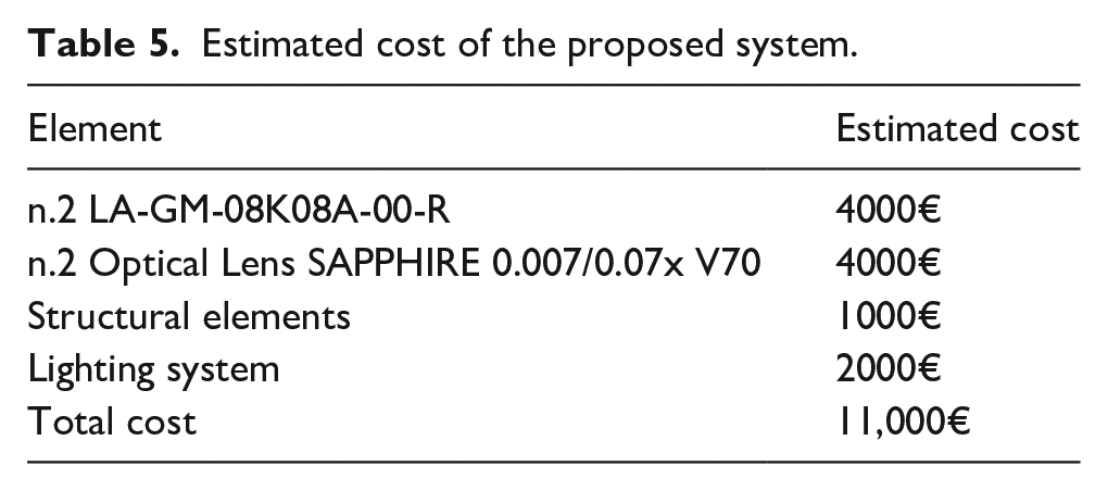
The estimated costs of the assumed construction solution are shown in Table 5.
Estimated cost of the proposed system.
Discussions and conclusions
In the last few years AR technology has been successfully used in various industries such as gaming, education, and healthcare, among others. In fact, by overlaying virtual information onto the real-world view, AR can enhance the perception and interaction with the physical world.
In the context of fabric defect detection, AR could provide a more intuitive and effective way for operators to locate and identify defects on the fabric surface. This can speed up the inspection process and reduce the likelihood of missing defects that might be overlooked with traditional methods.
As explained above, the innovation of the proposed solution lies in the concurrent work of an operator and an automatic detection system that can assist the operator in the task of detecting fabric defects by suggesting the inspection of specific areas. Thus, it would be an auxiliary system that could somehow bring certain regions to the operator’s attention during visual inspection. By implementing the proposed system, there would be no need to replace the human-based defect control with a completely automated system, which has several drawbacks. First, the automated system does not allow the operator intervention for fixing repairable defects (such as easy-to-mend threads, easily removable stains, dust or dirt i.e. normally blown away with compressed air). Furthermore, automated approaches can label the position of most defects, together with their typology and severity, but the label is typically placed on the digital image of the inspected fabric. This may be an issue since in the common textile control the defect is marked physically on the inspected fabric, to ease the subsequent manufacturing phases (e.g. the cut of the fabric, which has to avoid the damaged parts). By using the proposed architecture, instead, the operator would be supported in fabric defect detection (including the size and the severity of the defect) but also allowed to intervene for fixing minor issues and to physically mark the defect. Once the control of the entire fabric is completed, the subsequent manufacturing of the fabric could be carried out by using traditional methods, that is, without the need to re-control the digital data to locate the defective areas, hence perfectly integrating the technology within the existing production line.
Possible hardware and software solutions for implementing such a system have been analyzed in the above paragraphs. In general, the success of AR for fabric defect detection would be determined by a number of factors, including the detection system’s accuracy and reliability, the quality of the AR display and tracking, and the system’s cost-effectiveness. The cost of equipment has been analyzed and would be determined by the cameras, lenses, projectors, and processing systems used, as well as any software or hardware development required. In conclusion implementing such methods has the potential to reduce the number of defects and improve product quality, potentially saving money through reduced waste, rework, and customer returns.
Footnotes
Declaration of conflicting interests
The author(s) declared no potential conflicts of interest with respect to the research, authorship, and/or publication of this article.
Funding
The author(s) received no financial support for the research, authorship, and/or publication of this article.