
Abstract
The braiding angle of 3D braided carbon/carbon composites (C/CCs) will change during high temperature fatigue loading, which will affect the fatigue properties of 3D braided C/CCs. In order to realize this dynamic simulation in the high temperature fatigue life prediction of 3D braided C/CCs and further improve the prediction accuracy of high temperature fatigue life of 3D braided C/CCs, a high temperature fatigue life prediction model of 3D braided C/CCs considering the change of braiding angle with fatigue cycle number was established. The establishment of the prediction model mainly includes: a meso-scale representative volume elements (RVEs) of 3D braided C/CCs considering yarn direction and fiber bundle cross-section shape is established at the meso-scale; the high temperature residual stiffness and residual strength models of fiber bundles considering high temperature and stress level are established. Based on the experimental data characteristics of high temperature fatigue residual stiffness of 3D braided C/CCs, a mathematical model of cycle number/braided angles (CN/BAs) is established. The fatigue life prediction model was used to predict the 3D braided C/CCs at 700°C and stress levels of 87% and 85%. The results showed that the prediction error of single flower node was less than 5%. The fatigue life prediction error is less than two times the tolerance.
Introduction
Due to their high specific strength, high specific stiffness, good ablative performance, friction performance and thermal vibration resistance,1,2 C/CCs have been widely used in many industrial fields, especially in aeronautical and astronautical structures at high temperature.3,4 The difference between conventional 2D braiding and 3D braiding is that 2D braiding is limited by size and thickness, 5 while 3D braided technology has the characteristics of 3D multidirectional orientation and overall continuous distribution of fiber, 6 which can prevent or slow the propagation of interlayer cracks of composite materials under impact load, thus greatly improving the interlayer performance of composite materials.7,8
3D braiding refers to the orientation of braided fibers (or yarns) along the forming direction of the fabric at a certain angle. 9 The thickness of the braided fabric is more than three times the diameter of the braided yarn or fiber bundle, 10 and the yarns are intertwined in the thickness direction. The braiding processes of 3D braided composites include two-step method, four-step method, multi-layer braiding method and multi-step method. Among them, four-step method and two-step method are the two most important methods in this field. 11 The weaving method and design of 3D braided components depend on the final load conditions. The basic parameters and final use of 3D braided junction composites determine the manufacturing technology of prefabricated parts. 12 Bilisik and Sahbaz 13 established various 3D braided unit cell structures and 3D braided axial unit cell structures based on the different process parameters of braiding morphology and number of layers. It was found that the braiding mode affected the three-dimensional braided unit cell structure, while the 3D braided axial unit cell structure was affected by the 3D braided unit cell. The number of layers and the blocking conditions affect the thickness and width of the three-dimensional braided unit cell structure and the three-dimensional braided axial unit cell structure, respectively. This is because the increase in the number of layers will lead to an increase in the braiding length and the surface yarn length. 14 This finding has a guiding role in more accurate understanding of the three-dimensional braided preform structure and the establishment of a finite element model. And it is convenient to study the mechanical properties of three-dimensional braided composites.
Compared with other materials, the fatigue characteristics of 3D braided C/CCs are special. Liao et al., 15 and Zhu et al. 16 carried out fatigue experiments for 3D braided C/CCs at room temperature. They investigated variation of mechanical properties of 3D braided C/CCs under fatigue loadings. The experimental results revealed that fatigue limit stress level of 3D braided C/CCs exceeds 90% of the static strength, and the tensile residual strength can exceed the initial strength. It can be considered to enter the infinite life stage when the fatigue life of 3D braided C/CCs exceeds 104 cycles.
At present, the fatigue theory of 3D three-dimensional fabric composites is mostly studied by using the meso-cell method, and the fatigue characteristics of 3D three-dimensional fabric composites are simulated by establishing residual stiffness, residual strength models and fatigue failure judgment criteria. Such as Zhu 17 established life prediction model of 3D braided C/CCs at room temperature base on residual stiffness model of Yang et al. 18 The prediction model of Zhu Yuanlin takes into account the microstructure of carbon fiber bundle and carbon matrix and the weak interface characteristics of carbon/carbon composites. However, it fails to take into account the influence of temperature and oxidation on the fatigue characteristics of carbon/carbon composites and the structural changes under fatigue loadings, so the prediction accuracy is low. Many researchers19–21 have reported about mechanical properties and fatigue life prediction of resin matrix 3D braided composites by meso-cell method and continuum damage mechanics. These models also did not take into account the structural changes of the fiber preform during fatigue loadings. However, due to the better curing effect of resin base on the fiber preform, the prediction accuracy was relatively high. Song et al. 21 carried out the fatigue life prediction of 2.5D resin matrix composites at room temperature and 180℃. It is a rare research achievement that can predict fatigue life of stereostructure fabric composites considered temperature.
The above research results show that the temperature influence is rarely considered in the theoretical prediction models of 3D braided C/CCs, and the effect of structural changes on fatigue effects is not considered. This paper is a fatigue life prediction method for the high temperature fatigue characteristics of 3D braided C/CCs. It is an expansion of the existing 3D braided composite fatigue papers to the field of high temperature and fiber bundle structure changes. Firstly, the unit cell model of 3D braided C/CCs is established based on the meso-scale. Then, based on the gradual damage theory, a residual stiffness and residual strength model for C/CCs under high temperature environment is established. After that, by observing the length change of the test piece during the experiment and combining with the relevant literature reports, the basic point of view that the fiber bundle of the 3D braided C/C composite material will undergo structural changes during the tensile/tensile fatigue process was established. From this point of view, a CN/BAs model was established to describe the change of braiding angle with the number of cycles. Finally, the high temperature fatigue life prediction model of 3D braided C/CCs is established by combining the above theories. The fatigue life of 3D braided C/CCs at 700°C was predicted accurately.
Experiment
Preparation of specimens
In this paper, the perform material is T300 and 3 k carbon fiber bundles and obtained by 1 × 1 four-step weaving. After pouring resin, the perform need heat treatment at 2200℃, and atmospheric pressure carbonization, high-pressure carbonization and graphitization about four cycles. There are anti-oxidation coating on surface of specimens which are mixed by silicon, phosphorus, and other compounds. After the coating are dissolved, it is applied on the surface of the specimens which sintered at 700℃ for 5–7 days. The sizes of specimens are 200 mm × 25 mm × 4 mm shown in Figure 1. The material parameters of specimens are shown in Tables 1 and 2.

Specimens of 3D braided carbon/carbon composites.
Structural parameters of specimens.

Mechanical properties of specimens at 700℃.

Experiment conditions
Mechanical properties of engineering materials are obtained from testing. 22 It is the most effective method to carry out the experiment 23 by using the systematic method and considering all the factors. 24 This method is called experimental design. 25
MTS-633 is used to be carried out the tensile fatigue experiment in this paper shown in Figure 2. The maximum range of the force sensor of the system is 10 kN, and the gage length of extensometer is 12 mm. Fatigue experiment conditions are shown in Table 3.

Site photo of high-temperature fatigue test of 3D braided carbon/carbon composites.
Fatigue experiment condition.

Experimental data
The experimental data are shown in Table 4.
Tensile fatigue life of 3D braided C/CCs at 700℃.

Fatigue life prediction mode
The temperature-dependent fatigue life prediction model of 3D braided C/CCs subjected to uniaxial tension-tension loadings mainly includes: mechanical properties degradation model of fiber bundle at high temperature, parameters confirmation of CN/BAs model; RVE model; fatigue damage criteria. The models of residual stiffness and residual strength of fiber bundles are used to simulate the damage of 3D braided C/CCs under fatigue loadings at high temperature. The parameters confirmation of CN/BAs model is used to obtain the dynamic change of RVE geometric model parameters for 3D braided C/CCs. The fatigue failure criterion is used to determine the failure of the element and the final failure of the material on 3D braided C/CCs.
3D braided carbon/carbon composite residual stiffness model
Fiber bundle residual stiffness model
In the study of fatigue damage of composites, damage factors are generally introduced to characterize the amount of damage, and it also can be expressed by the following equation.

Where E0 is initial stiffness; E(n) is residual stiffness of material after N fatigue cycles; E(N) is critical stiffness of material in failure.
Since DE can be expressed as a function of life ratio n/N, the regularization form of equation (1) can be expressed as:

The regularized form of equation (2) can be expressed as:

Numerous experimental studies26–31 have shown that stiffness degradation of composite laminate have three stages. They include the early rapid descent stage, the middle slow decline stage and the late rapid descent stage. Equation (4) shows stiffness degradation model by Mao and Mahadevan 32 can well describe the three degradation stages of composite laminate.

Where q1, m1, m2 are experimental parameters.
Simultaneous equations (1)–(4), the residual stiffness degradation model in the fatigue loadings process can be defined as:

Considering the influence of stress level, temperature, and oxidation rate, the parameter q1 is defined as follows:

Where α1, β1, k1 are experimental parameters;
Lee 33 obtained the relationship between E(N) and E0 considering temperature influence in the course of studying the fatigue damage of laminates at room temperature.
Now we improve Lee’s model. The improved model can be expressed as:

Where c, d1, d2 are experimental parameters.
According to equations (5)–(7), the residual stiffness model of composite fiber bundles can be expressed as:

If k(T) = 0, the residual stiffness model without oxidation at high temperature can be expressed as:

Fiber bundle residual strength model
Similar to residual stiffness, the functional relationship between damage factor and residual strength is shown in equation (10).

Where S(n) is residual strength; S(N) is critical strength of material in failure.
Obviously, material damage when residual strength is reduced to the maximum fatigue load. And then, equation (10) can be translated into:

Assuming that the form of strength degradation is the same as that of stiffness, equation (11) can be expressed as:

Where q2, l1, l2 are experimental parameters.
Considering the influence of stress level, temperature, and oxidation rate, the parameter q2 is defined as follows:

Where α2, β2, k2 are experimental parameters.
The residual strength model of composite fiber bundles can be expressed as:

If k(T) = 0, the residual strength model without oxidation at high temperature can be expressed as:

CN/BAs model and parameters confirmation
There is a special phenomenon in fatigue experiment of 3D braided C/CCs: the residual stiffness of 3D braided composites increases first and then decreases under fatigue load. The main reason is that the internal braided angle of 3D braided C/CCs decreases gradually under fatigue load. In this paper, it is assumed that braided angle and cycles in the 3D braided C/CCs follow the mathematical relationship of equation (16). The validity of CN/BAs model will be verified in pitch length calculation.

Where γ(0) is initial braided angle; γ(n) is braided angle at n cycles; a, b are experimental parameters.

The residual stiffness model of 3D braided C/CCs can be expressed as:

RVE model
Geometric model
A 3D braided C/CCs cell model with hexagonal cross-section and straight direction of the fiber bundles is established considering the mutual compression of the fiber bundles, as shown in Figure 3.

Geometric model of cell model.
Periodic boundary conditions
The internal structure of 3D braided composites is periodic. In order to ensure the continuity of displacement and stress, periodic boundary conditions should be applied to the model. The macroscopic displacement constraints for the corresponding nodes on surfaces can be defined as 34 :

Where
The

Where
The constraint equation for 3D braided composites can be expressed as:

Where U, V, W are Displacement of nodes in the
Simulation of fiber bundle/matrix debonding
The displacement coupling of
Fatigue damage criteria
Fiber bundle failure
The 3D Hashin static strength failure criterion is extended to fatigue in this paper because the 3D Hashin failure criterion can well describe various failure forms of fiber bundles in composite materials in damage. The fatigue failure criterion can be defined as:
(1) Fiber fracture failure in fiber bundle:

(2) Matrix failure in fiber bundle:
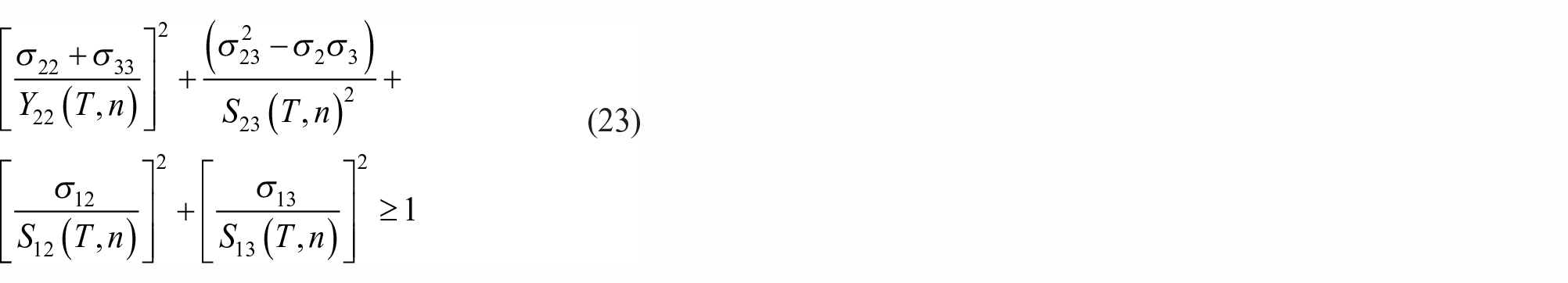
Where
Criteria for final failure of specimens under fatigue loadings
With the increase of cycles, the fiber damage in the composite increases gradually during fatigue loadings. The composite material is destroyed instantaneously when fiber damage reaches a certain value. The final failure can be defined as:
(1) The fracture damage runs through the whole cell cross section.
(2) The stress in cell decreased with the increase of strain.
Fatigue prediction process for 3D braided C/CCs
The calculation process of high temperature fatigue prediction of 3D braided C/CCs is shown in Figure 4. The fatigue analysis and calculation process of 3D braided C/CCs is mainly composed of the following aspects.

Flow chart of fatigue calculation at high temperature.
(1) Complete RVE model by geometric model of 3D braided C/CCs, meshing, material definition of component, and loading of periodic boundary conditions.
(2) Load constant temperature field and initial displacement loadings. Choose residual stiffness and residual strength models of fiber bundles under corresponding working conditions whether considering the influence of oxidation or not.
(3) The average stress of cell can reach the maximum fatigue stress level by means of dichotomy. Stress analysis and failure analysis are carried out by 3D Hashin fatigue failure criterion considering temperature, stress level, and cycles. Check the elements status. If all elements are not damaged, determine whether the maximum number of cycles is reached. If the cycles are reached, stop the calculation, or increase cycles, degrade material properties, and modified geometric model. The cycles are calculated until specimens finally fails.
Model verification
CN/BAs model verification
CN/BAs model parameters
The residual stiffness data of 3D braided C/CCs specimens under 87% stress level at 700℃ are fitted by equation (18), the results shown as Figure 5 and equation (24).

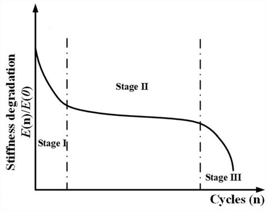
General trend of residual stiffness curve of composite materials.
The relationship of 3D braided C/CCs between braided angle and cycles in this paper can be defined as:

In general, the general trend of the tensile-tensile fatigue residual stiffness curve of composite materials is shown in Figure 5. That is to say, the tensile-tensile fatigue residual stiffness curve of the composite material includes the initial drop zone, the stable gradual drop zone and the final sudden drop zone. The residual stiffness curves of composite laminates and 2.5D angle-interlock woven composites are given in Häusler et al. 35 and Song et al., 36 as shown in Figures 6 and 7. It can be seen from Figures 6 and 7 that they all conform to the change rule of Figure 5. Figure 8 shows the tensile-tensile fatigue residual stiffness test results of coated 3D braided C/CCs with a stress level of 87% at 700°C. It can be seen from Figure 8 that the residual stiffness of the 3D braided C/CCs at 700°C is first increased, then kept unchanged, and finally suddenly decreased. This is very different from the change rule of tensile-tensile fatigue residual stiffness of composite laminates in Figure 5. The main reason is that the strength of the carbon matrix in the C/CCs is much lower than the fatigue load. After a small number of cycles, it gradually fails, so that the fiber bundle cannot be completely fixed by the matrix, the braiding angle of the fiber bundle is gradually reduced, and the fiber bundle tends to the load direction. In this stage, the fiber damage is small, and the 3D braided C/CCs exhibits stiffness strengthening during this stage. As the number of cycles increases, the fiber damage gradually increases, which offsets the stiffness increase due to the change of the braiding angle. During this stage, the stiffness of the 3D braided C/CCs changes little, and the braiding angle changes little. When the fiber is damaged to a certain extent, the 3D braided C/CCs cannot withstand the fatigue load. At this stage, the material stiffness will decrease sharply, and the fiber will be destroyed in a large area. The 3D braided C/CCs reach the fatigue life and finally fail.

Residual stiffness curve of composite laminates. 35

2.5D angle-interlock woven composites residual stiffness model. 36

The fitting result of residual stiffness data for 3D braided C/CCs specimens under 87% stress level at 700℃.
Figure 9 shows the residual strength test results of coated 3D braided C/CCs with a stress level of 83% after 105 cycles at 700°C. It can be seen from the figure that the tensile strength of 3D braided C/CCs is strengthened after fatigue loading. This is consistent with the fatigue characteristics of 3D braided C/CCs at room temperature in Liao et al. 15 and Zhu et al. 16 , that is, the tensile strength of 3D braided C/CCs is strengthened after tensile/tensile fatigue loading. The fitting correlation coefficient R = 0.918 in Figure 8 shows that the high temperature residual stiffness prediction model of 3D braided C/CCs established in this paper can better describe the residual stiffness evolution of 3D braided C/CCs at 700°C.
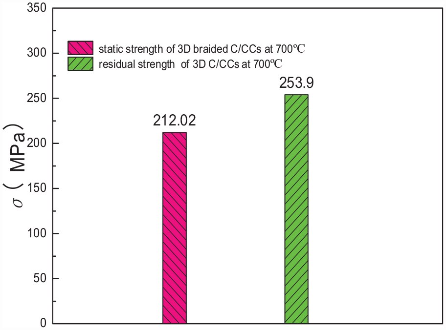
Residual strength and static strength of 3D braided C/CCs.
According to equation (24), the braiding angle of 3D braided C/CCs varies with the number of cycles as shown in Figure 10. It can be seen from the figure that the braiding angle gradually decreases with the increase of the number of cycles, and the decreasing trend gradually decreases. At the initial stage of fatigue loading, the braiding angle decreases rapidly, and the fiber bundles gradually approach the load direction. The residual stiffness of the 3D braided C/CCs is strengthened during this period. Then the decrease rate of braiding angle decreases, and at a high stress level, the fibers in the 3D braided C/CCs begin to damage gradually, and the residual stiffness of the 3D braided C/CCs tends to be stable during this period. When the number of cycles is close to the fatigue life, the fiber damage in the 3D braided C/CCs reaches the fracture condition, the residual stiffness suddenly drops, the material suddenly breaks, and finally completely breaks.
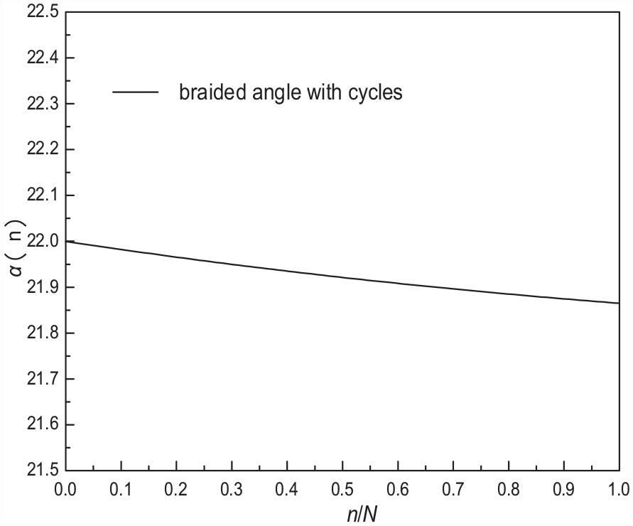
The curve of braided angle with cycles.
CN/BAs model verification
It is difficult to measure braided angle in situ during fatigue loadings. In order to verify the validity of equation (25), the length variation of specimens under fatigue loadings are measured in this paper. It can be equivalent to the change of pitch length using equation (26).

Where
Assuming the shape of the 3D braided composite fiber bundle section is elliptic, the relation between the length of pitch length and braided angle can be defined as:

Where
The comparison between calculation results of CN/BAs model and experiment results are shown in Table 5. The initial length of specimens working section is 100 mm.
CN/BAs model calculation results and experiment results.

Fatigue prediction model verification of 3D braided C/CCs at high temperature
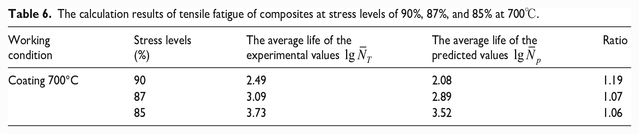
The calculation results of tensile fatigue of composites at stress levels of 90%, 87%, and 85% at 700°C is shown as Table 6. Figure 11 shows the comparison between the predicted and experimental fatigue life at 700°C of the coated uncut 3D braided C/CCs. From the diagram, it can be seen that the prediction results of the fatigue life prediction model established in this paper are within two times the dispersion band, indicating that the model has high prediction accuracy. Comparison of stiffness degradation between predictive values and experiment values is shown as Figure 12. According to the prediction results, the results of fatigue life calculation and residual stiffness calculation are low, that is, the results obtained by the life prediction method established in this paper are conservative, which is conducive to practical engineering application.
The calculation results of tensile fatigue of composites at stress levels of 90%, 87%, and 85% at 700℃.

Comparison of fatigue predicted values and experimental values of coated uncut 3D C/CCs at 700°C.

Untrenched three-dimensional braided C/CCs coated at 87% stress level.
The fatigue corresponding damage propagation photographs are shown in Figures 13 and 14.

The fatigue corresponding damage propagation of fiber bundle.

The fatigue corresponding damage propagation of matrix.
It can be seen from Figure 13 that due to the high stress level of fatigue load, the material has a certain fiber bundle damage under one cycle of fatigue loading, and the damage is concentrated in the stress concentration area of the unit cell. With the increase of the number of cycles, the area of fiber damage in the unit cell gradually increases. When the number of cycles reaches 2001, the material meets the requirements of fatigue failure determination, and the material undergoes fatigue failure. It can be seen from Figure 14 that the pure matrix region begins to damage under one cycle of fatigue load. When the number of cycles reaches 601, the pure matrix region completely fails.The damage element proportion of the components in cell vary with cycles is shown in Figure 15.

The damage element proportion of the components in cell vary with cycles.
Conclusions
(1) Aiming at the structural change characteristics of three-dimensional braided C/CCs during high temperature fatigue loading, a CN/BAs model for 3D braided C/CCs under fatigue loadings is proposed in this paper which can describe the relationship between cycles n and experiment parameters b. The CN/BAs model is combined with the flower section calculation formula to obtain the change of the test section length with the number of cycles. The comparison test results show that the calculation error is less than 5%, and verifies the accuracy of the CN/BAs model.
(2) Based on the residual stiffness theory, the high temperature residual stiffness and residual strength models of C/CCs fiber bundles were established by introducing parameters such as oxidation rate, temperature, stress level, and high temperature heat treatment temperature. The high temperature residual stiffness model of 3D braided C/CCs was established by combining the high temperature residual stiffness model of the fiber bundle with the CN/BAs model. The tensile-tensile fatigue test of 3D braided C/CCs at 700°C was carried out, and the residual stiffness data of 3D braided C/CCs at 700°C were obtained. The results show that the residual stiffness curve of 3D braided C/CCs at 700°C increases first, then becomes stable, and finally decreases suddenly. The high temperature residual stiffness model of 3D braided C/CCs established in this paper has a high correlation with the test results, which verifies the accuracy of the high temperature residual stiffness model of 3D braided C/CCs.
(3) Based on the meso-scale unit cell theory, combined with the high temperature residual stiffness and residual strength model of C/C composite fiber bundles and CN/BAs model, a fatigue life prediction method of 3D braided C/CCs considering the effects of oxidation rate, temperature, stress level, and braided angle is proposed. The prediction method considers the meso-scale unit cell structure of 3D braided C/CCs, the change of braided angle during fatigue loading and the damage evolution and failure mode of fiber bundles. The fatigue life of 3D braided C/CCs at 700°C was predicted by this method. The comparison of experiment results shows that the prediction error is within two times tolerance zones. The accuracy of the method is verified.
Footnotes
Appendix
Declaration of conflicting interests
The author(s) declared no potential conflicts of interest with respect to the research, authorship, and/or publication of this article.
Funding
The author(s) disclosed receipt of the following financial support for the research, authorship, and/or publication of this article: Jiangsu University of Science and Technology. Grant ID:1142931905.