
Abstract
Braided tubular composites have been widely applied in various industries, such as aerospace, automobile, and sports, due to their light weight, high fatigue resistance, and good corrosion resistance. It is necessary to study the effect of the preform parameters on the thermodynamic behavior of braided tubular composites. A thermoelastic model of braided multi-layered tubes was developed to investigate the effect of changing the braiding angle on the thermal stress distribution. The thermal stress distributions of different structures were analyzed based on the model. The analysis results show that the layer-by-layer braiding angle critically affects the gradient of the axial thermal stress. The change rates of the braiding angle also significantly affect the gradient of the radial thermal stress. The theoretical results were verified by finite element analysis. These results are beneficial to the optimal design of braided composite tubes subjected to thermal load.
Keywords
Introduction
Braided composites are widely used in the aerospace, automobile, sports, and marine industries because of their high specific modulus, strength, and fatigue resistance. 1 Tubular braided composites have several advantages, including being significantly lighter than traditional monolithic materials and having the ability to tailor the layup design to match the thermal and mechanical loading conditions being applied. 2 Circular braiding technology produces a seamless multi-layered fabric over a shaped mandrel enabling the production of near-net shaped preforms for hollow fiber-reinforced composites components in an automatic manner,3,4 which is readily available, cheap, high production efficiency. 5 With the advent of increasing capability requirements in such applications, accurate methods of optimizing the layup design for multi-layered tubular composites structures are critical to achieving the desired level of lightweight design without compromising on thermomechanical performance. 6
Fiber reinforced plastic composites (FRPC) are replacing traditional materials in some important types of equipment and structures that operate under high-temperature or changing temperature conditions. 7 The thermo-elastic analysis of FRPC has attracted a large amount of attention. Longbiao 8 and Jamshidi et al. 9 studied the effect of thermal changes on the mechanical properties of FRPC. The effects of the thermal fatigue loading on tensile behavior and the effects of the thermal shocks on maximum stress, strain, and elastic modulus were analyzed. Kucher et al. 10 studied the thermoelastic behavior of FRPC using a combination of heat transfer analysis and FRPC layered arrangement technology. The results show that the thermal stress along the fiber direction is strong. Li et al. 11 analyzed the effects of temperature on the shear performance of FRPC through double-notch shear tests, and the results showed that the shear strength decreased as temperature increased. Wen et al. 12 established a meso-scale finite element model to analyze thermal residual stress of FRPC, the results show that the change in temperature and stress gradient led to cracking and peeling at the interface of fiber and matrix. Similar to this research, these studies have taken into account the effects of thermal on the mechanical properties of FRPC. However, in the literatures mentioned above, the effect of structural parameters of FRPC on thermo-elastic has not been investigated. It should be noted that the different architectures may greatly influence the high-temperature responses of the braided composites. Thus, it is essential to study the effect of mesoscopic features on performance for guiding the structural design of braided composites. 13
Grading material properties are known to enhance the mechanical performance of components. The strength of FRPC was reported to be improved by using a matrix grading structure. 14 Hai 15 dispersed two groups of carbon fibers with equal quality in cement mortar; they referred to the layered and gradient distribution separately and calculated the corresponding thermal stress value. The results indicated that compared with the carbon fiber layered distribution, gradient distribution decreases the maximum thermal stress. Li et al. 16 prepared gradient FRPC with continuously increasing fiber volume fraction from the bottom to the top surface and studied the ablation resistance performance of gradient fabric. The microstructure analysis showed that gradient fabric has good ablation resistance due to the thermal expansion and the densification of the integrated gradient fabric. Huang et al. 17 prepared a gradient FRPC laminate to investigate modal performance and vibration behavior, and they analyzed the influence of the fiber volume fraction gradient distribution on the modal performance, the results suggested that the gradient distribution of fibers improves the efficiency of pre-strain to produce recovery stress. Feng et al.18,19 and Zheng et al. 20 have reported that multiscale gradient modulus intermediate layer with rigid-flexible can enhance the interfacial adhesion of fiber and matrix. The researches mentioned above provided a valuable reference for obtaining high performance by using the graded structure. As an important structural parameter of FRPC, braiding angle has an important influence on mechanical performance. However, there is no literature to our knowledge, to investigate the effect of graded braiding angle on the thermal-elastic properties of FRPC.
In this study, an angle-graded composite tube model is proposed, in which the braiding angle varies continuously as a function of its position along the radial direction based on the flexibility of the textiles. A thermoelastic problem of a multi-layered tube made of braided composites was investigated. The numerical results are presented to show the effect of angle-graded on the distribution of thermal stresses.
Multi-layered braided tubular composite
Structure of preform
The circular braiding machine and braiding process are shown in Figure 1. Two sets of carriers are moved on a sinusoidal path in opposite directions on the braider track plate by horn gears, as shown in Figure 1. The take-up mechanism drives the mandrel to move along the tube axial direction at a certain speed. These yarns interlace with each other and are pulled down toward the fell-point, where they meet and become tubular braid. The designed braiding angle can be achieved by controlling the take-up speed and the angular speed of the carrier. Multi-layered braided structures are generally produced by over-braiding on previously formed tubular braids. After the first layer of braid is formed, the mandrel moves a certain distance along the axial direction due to the take-up system. Put the mandrel and the first layer back to the original position and braid the second layer on the previously formed braid. Repeat the above process several times to form the multilayered braids. After the multi-layered preform is formed, the mandrel and the braid are put into the mold, and vacuum-assisted resin transfer molding (VARTM) is used for curing. After curing, remove the mandrel to obtain a multi-layered braided composite.

Preparation of the braided multi-layered tubular preform.
Figure 2(a) shows a diamond (1/1) braid. It involves two groups of fiber tows that interlace at a braiding angle of ±δ. The braiding angle can range from 15° to 75°. 21 The coordinate system of the braided multi-layered tube is shown in Figure 2(b) and (c). The global coordinate z, r, and θ represent the axial, radial, and circumferential directions of the tube, respectively. In the material coordinate system, 1-axis and 2-axis are the fiber direction and transverse direction, respectively. The braided structure is composed of two fiber tows with opposite directions about the axis (±δ), as shown in Figure 2(b). To simplify the model, the single-layer braided structure is considered as a combination of two layers of angle-ply laminates with opposite directions, as shown in Figure 2(c).
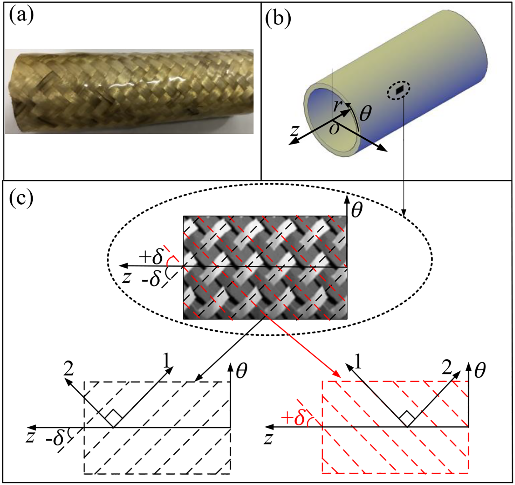
(a) A photograph of the diamond 1/1 braided composites, (b) global coordinate, and (c) material coordinates and ±δ tows.
Performance of braided composite tubes
According to the generalized Hooke’s law, the constitutive relation of the single-layer can be written as
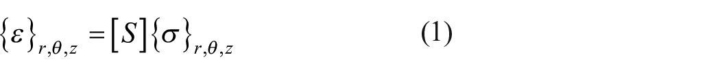
where {ε} r,θ,z and {σ} r,θ,z are vectors of strain and stress in cylindrical coordinates, respectively. [S] denotes the compliance matrix of the angle lay-up.
According to Figure 2(c) and the assumptions above, the single-layer braided structure is considered as a combination of two layers of angle-ply laminates with opposite directions (±δ). Each layer is an orthotropic material. The shear coupling terms are zero due to the (±δ) configuration.
The matrix [S] can be written in cylindrical coordinates as follows:

The effective elastic properties are given by

The stiffness matrix of the angle-ply can be obtained from the following relationship:

where Err, and Eθθ, represent the elastic modulus in the radial and circumferential directions, Grθ is the shear modulus. vrθ and vrθ are Poisson’s ratios. In this study, the elastic constants related to the thickness are assumed as Ezz = E33 = E22, Gθz = Grz = Grθ. E11, E22, G12, and v12 are on-axis elastic properties in the corresponding direction.
The relationship between the off-axis and on-axis elastic properties of the angle-ply has been established in the previous manuscript. The on-axis elastic properties are obtained from the elastic properties of the fiber and matrix using the volume average method. 22

where

The unit cell and cross-section view of the yarn path in the braid correspond to the 1 × 1 biaxial braided composites; these are schematically shown in Figure 3.
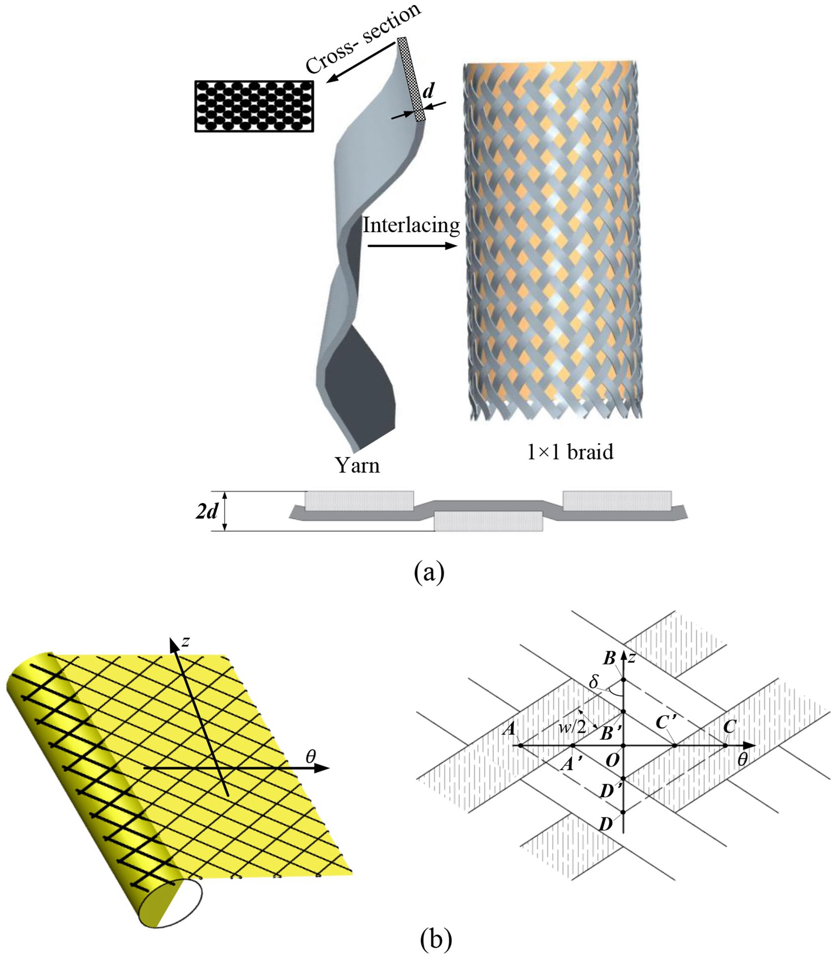
(a) 1 × 1 braid architectures and yarn cross-section and (b) flatten the tubular braid to get the plane development and unit cell of fabric.
The yarns are interlaced with each other to get a layer, and the layers are stacked on top of each other to get the thickness. A unit cell of the 1 × 1 braid microstructure, as shown in Figure 3, can be analyzed to reveal the microstructure of the braided composite tube. A, B, C, and D are the points where the yarn’s center lines intersect.
The width of one unit cell can be obtained through a geometric calculation:

where N is the number of carriers, and r is the mandrel radius.
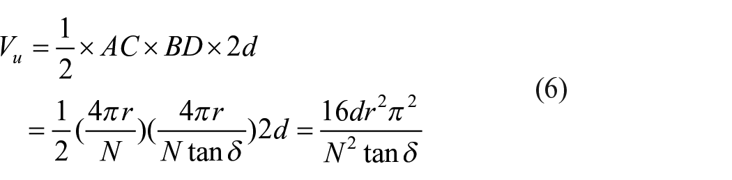
We can flatten the cylinder to a rectangular plane, as shown in Figure 3. The volume of unit cell can be computed as follows 23 :
The volume of yarn Vy in the unit cell can be expressed as

The volume of fiber Vx is given by the following equation

where η is the packing fraction of yarns ranging from 0 to 1.
The expression of the fiber volume fraction Vf of a single layer can be obtained by combining equations (6)–(8):

where (1 + Z) (1 < 1 + Z < 2) is the correction factor for the crimp due to yarn interlacement.
The cover factor Cf of a single layer can also be obtained through calculations 23,24:

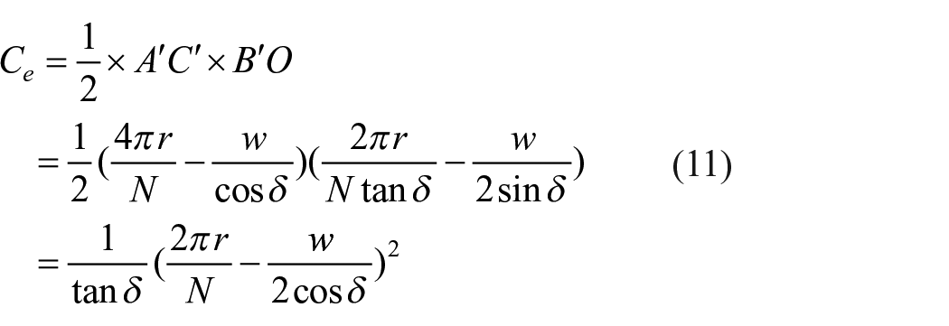

where Cu is the half of the unit cell area (ΔABC) and Ce is the half of the space area (ΔA′B ′C′), as shown in Figure 3.
Thermoelastic model of tubular braided composites
Assumptions
The following assumptions were made to establish the model. The yarn cross-section remains unchanged. The yarn properties are considered transversely isotropic, and the engineering elastic constants do not vary with temperature. The temperature field of the braided composite tube is the steady-state temperature field without an internal heat source.
Steady-state temperature field of composites tube
The heat equation for steady-state heat conduction in a braided composite tube can be written as follows 25 :

where r represents the radius, and kr is the thermal conductivity coefficient in the radial direction. According to the structural characteristics of the braided multi-layered tube, the through-thickness conductivity kr is mainly affected by the interface properties of multi-phase composites.26 –28 The change of the braiding angle in the radial direction has no effect on the properties of the interface. Therefore, the thermal conductivity in the radial direction was considered a constant in this study.
Multiplying both sides of equation (13) by rdr and integrating them with respect to r leads to the following equation:

where Ri is the inner radius of the tube. Multiplying both sides of equation (14) by dr/rkr and integrating them with respect to r again leads to the following equation:

where C and D are undetermined coefficients determined by the boundary conditions.
In this study, the temperature values on the inner surface and outer surface of the tube were considered know conditions:
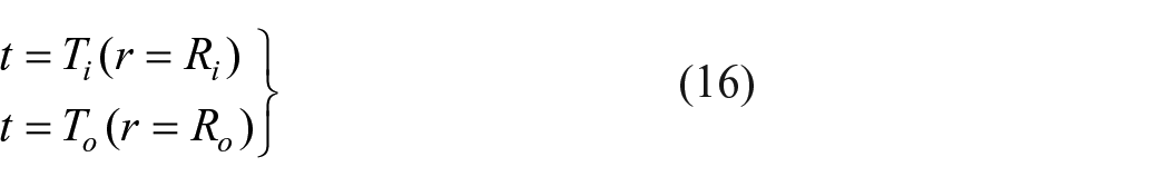
where Ri and Ro are inner and outer radii of the tube, respectively, and Ti, To are temperatures on the inner and outer surface, respectively as shown in Figure 4.

The cross-section of the braided tubular composites.
The temperature field can be derived as follows:

Thermal stress analysis of braided multi-layered tubes
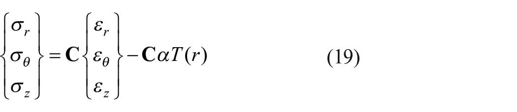
The constitutive equation of braided tubes for axisymmetrical thermoelastic problems is as follows:

where α represents the thermal expansion coefficient of the composite tube, which varies little along the radial direction in the tube and is regarded as a constant.
The stress expressed by strain can be represented as
where

The εz = 0 in the plane strain model. Thus, the following equation can be obtained:

Set

where C11(r), C12(r), C21(r), and C22(r) can be deduced from equation (20).
The equilibrium differential equation in polar coordinates is as follows:

The geometric equation is as follows:

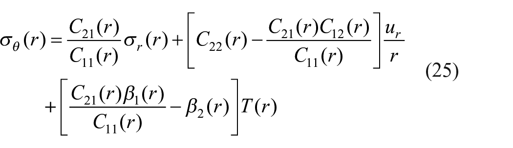
Equations (25) and (26) could be obtained by using σr(r), to represent σθ(r) and ur(r) in equations (22) and (24).

where C is the undetermined coefficient determined by boundary conditions. The expression of

By substituting equation (26) into equation (27) and then into the equilibrium differential equation, the differential equation about radial stress σr(r) can be obtained as follows:

where:

Equation (29) can be obtained by integrating r on both sides of the equal sign in equation (28).

where

C and D are constants that can be determined through the appropriate boundary conditions. This study focuses on the stress caused by thermal, the load on the inner and outer radius is assumed to be 0.

On the boundary of r = Ri, equation (29) takes the form.

In the above formula, all items except D are equal to 0, so D is also 0.
The following equations can be obtained by substituting the boundary conditions equation (31) into equation (29).

By substituting C and D into equation (29), an integral equation of radial stress can be derived.

where
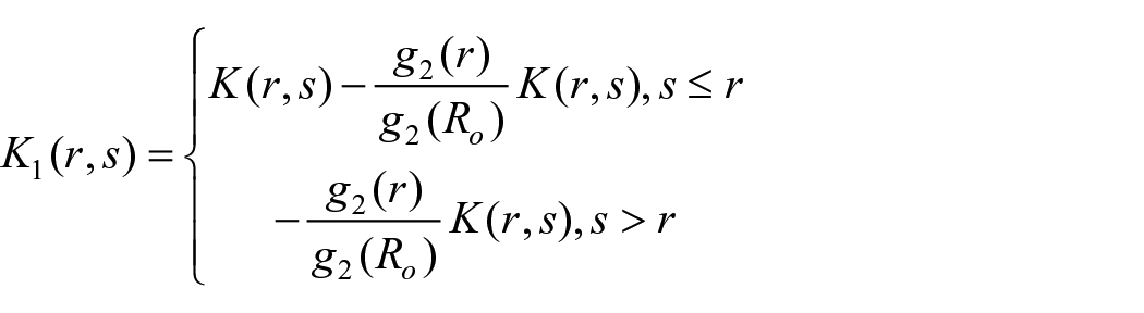
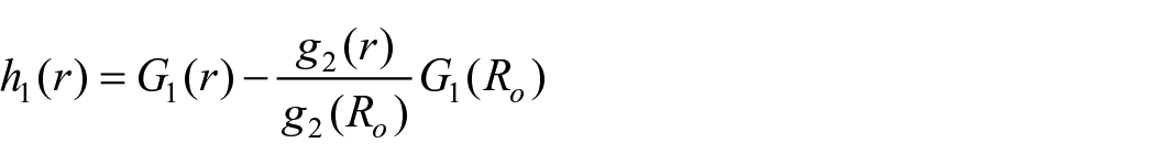
Radial stress σr(r) can be obtained by solving integral equation (33). The circumferential stress can be obtained from equations (17) and (18). The axial stress can be calculated by the following equation:

Results and discussion
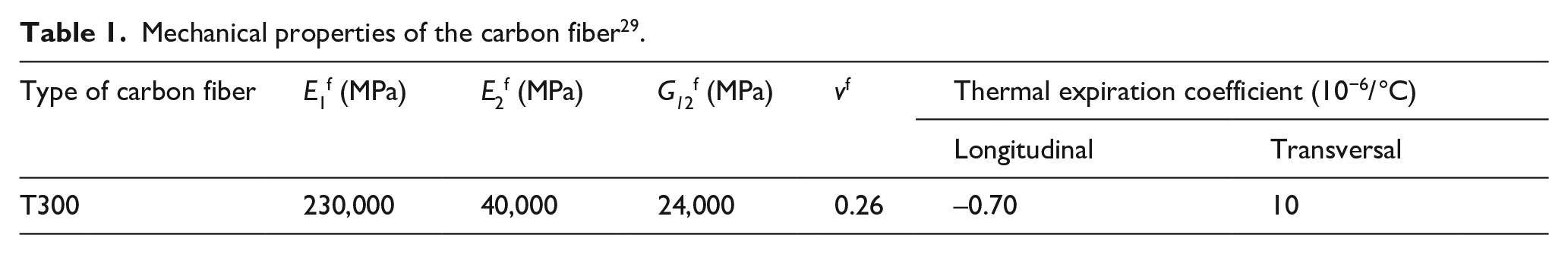
In this section, a numerical study is presented to study the effect of the gradient braided structure on the thermal stress of braided multi-layered composite tubes. It is assumed that the tube is subjected to a steady temperature field and the temperature at inner and outer radii are Ti = 200°Cand To = 50°C, respectively. Consider a braided multi-layered composite tube with inner and outer radii Ri = 10 mm and Ro = 15 mm, respectively. The number of yarn carriers N = 32. The yarn width w = 2.5 mm. The tube model has comprised of k perfectly braided plies, each with associated thickness j = 0.25 mm. The properties of the fiber and matrix materials used in the numerical examples are shown in Tables 1 and 2, respectively.
Mechanical properties of the carbon fiber 29 .
Properties of the matrix 29 .

The braiding angle δ(r) variations through the thickness of the braided composite tube are modeled with the power-law as follows:

where r is the effective radius, δi and δo are the braiding angles of the inner and outer surfaces, respectively, n is the power-law index of the braided composite tubes, Ri and Ro are the inner and outer radii of the composite tube, respectively.
The influences of the angle gradient direction and power-law index on the thermal stress were examined. Cases with a positive angle gradient and negative angle gradient are set, as shown in Figure 5(b). The positive angle gradient means that the braiding angle gradually increases in the radial direction from inner to outer, while the negative angle gradient is the opposite. To study the influence of the variation form of the braiding angle (convexity of the r-δ curve) on the thermal stress, the function images are taken as concave, straight, and convex, and the corresponding power-law index n in equation (35) is considered to have the following values: n = 0.5, n = 1 and n = 2. Figure 5(c) and (d) show the fiber volume fraction and cover factor characteristics of gradient structures that were braided with 15° to 75° braiding angles.

(a and b) Braiding angle gradient in the radial direction, (c) variation of Vf with r and n, and (d) variation of Cf with r and n.
Effects of angle gradient direction
To study the influence of the angle gradient direction, the numerical results were evaluated for the positive and negative angle gradient are shown in Figures 6 to 8. Figure 6 shows the plot of the radial stress along the radius. It can be seen from the figure that

Radial stress distribution in a gradient braided tube along the radial direction for some values of the power-law index.

Circumferential stress distribution in a gradient braided tube along the radial direction for some values of the power-law index.

Axial stress distribution in a gradient braided tube along the radial direction for some values of the power-law index.
Figure 7 shows the distribution of the circumferential stress along the radius of the tube. It can be seen from the results that the circumferential thermal stress is far greater than the stress in other directions and is the main stress in the braided composite tube. The circumferential stress decreases first and then increases along the radial direction. The maximum value is on the outer wall. The effect of gradient direction on circumferential stress is opposite to that of radial stress. In the negative angle gradient structure, the maximum stress decreases with the increase of the power-law index. Meanwhile, the maximum stress decrease with the decrease of the index in the positive gradient structure.
It can be seen from Figure 8 that the axial stress is most sensitive to the gradient direction. The axial stress distribution in the positive gradient structure is smaller than that in the negative gradient structure. The axial stress in all structures decreases along the radial direction.
Effects of power-law index
It can be seen from these figures that the value of the power-law index n has a significant effect on the stress distributions in the braided tubes, as shown in Figures 6 to 8. Furthermore, the effects of n on the stress distributions in the positive gradient structures are different from the negative gradient structures. For example, by increasing n from 0.5 to 2, the maximum radial stresses decrease by 39.39% in a positive gradient structure. The maximum value of the radial stress increases 54.07% by increasing n from 0.5 to 2 in a negative gradient structure. In these cases, the maximum radial stress of the negative gradient structure with a parameter of n = 5 is the minimum.
In Figure 7, the minimum and maximum of the circumferential stress increase with the increase of n in positive gradient structures. However, these stress values decrease with the increase of n in the negative gradient structures. For instance, increasing the power-law index n = 0.5 to n = 2 decreases the maximum and minimum circumferential stress by 18.62% and 54.92%, respectively.
From the above discussion, we found that the thermal stresses are closely related to the gradient braiding angle in the radial direction. The analysis was carried out with Abaqus finite element software for purposes of comparison. For the verification of the optimization of the gradient braided tubes, a gradient structure with a negative gradient and power-law index n = 0.5 and a non-gradient structure with a constant braiding angle (60°) were considered. The dimensions of the geometric model and properties of materials are based on the data given in Section 3.
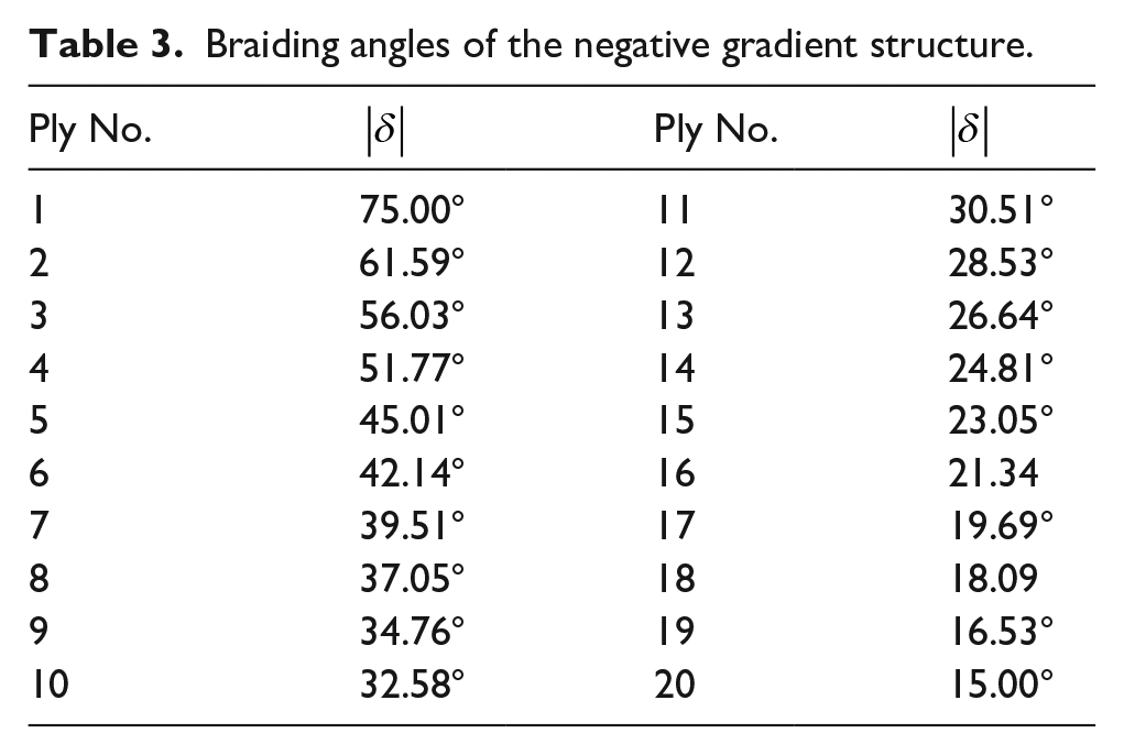
A C3D8R element type was used to discretize the braided tube. C3D8R is a three-dimensional eight-node deformable brick element with reduced integration. Previous studies have shown that these elements follow the constitutive law of integration very accurately and are suitable for nonlinear static and thermoelastic analysis. 30 The number of nodes is 63,140, and the number of elements is 56,000, as shown in Figure 9. The braiding yarn and matrix are assumed unidirectional fiber-reinforced composites based on the volume average method in section 1. The composite Layup properties are assigned to tube parts as shown in Figure 10, and the braiding angle is controlled by the rotation angle in the Layup property settings. Table 3 shows the braiding angles of the gradient structure.

The cross-sectional contour of finite element modeling of the tube with C3D8R elements.

Ply stack plot of the: (a) non-gradient structure and (b) negative gradient structure.
Braiding angles of the negative gradient structure.
The sequentially-coupled thermal stress analysis, including the analysis of the heat transmission and thermal stress analysis, was used in the calculation process. The first step was the heat transfer, and the interaction was the surface film condition on the outer surface of the composite tube. The boundary conditions were defined for the thermal analysis. Through simulations, the steady-state temperature distribution was obtained. In the second step, the temperature history in each node was employed as the thermal load in the subsequent mechanical analysis, and the distribution of the stresses in the composite tube was determined.
Different finite element analyses were carried out by changing the number of elements, as shown in Table 4. As the number of elements continued to increase, the stress values became more accurate. Figure 11 shows that when the number of elements is greater than 10,032, the influence of the mesh size on the final calculation results is greatly reduced. Therefore, the mesh size we set (number of elements = 56,000) met the accuracy requirements.
Comparison of the FEM results for different mesh sizes.


Radial stress (r = 1 mm) with different elements numbers.
The distribution of the radial stress, as well as the circumferential and axial stresses along the tube radius in non-gradient and negative gradient structures, is given in Figure 12. Figure 12(a) and (b) show the thermal stress nephogram of braided tubes, which are radial, circumferential, and axial from top to bottom. Figure 12(c) shows the stress-radius curve in the tube. Using the gradient structure decreases the maximum radial and axial stresses by 52.68% and 5.02%, respectively. However, compared with non-gradient structures, the circumferential stress of gradient structure decreases first and then increases along the radial direction. Furthermore, it can be seen that the FEM and theoretical results agree well with each other.
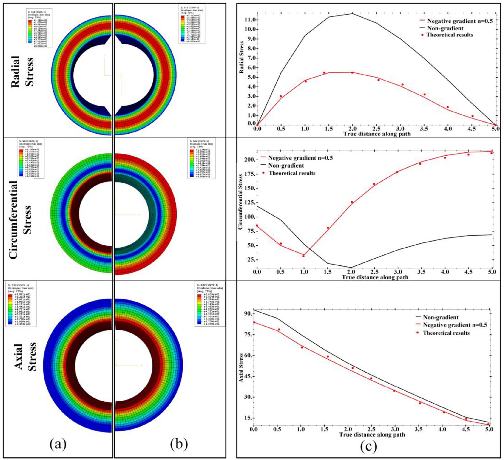
Thermal stress nephogram of braided tubes: (a) non-gradient structure, (b) negative gradient structure, and (c) stress-radius curve.
Conclusions
The effect of changing the braiding angle on the thermal stress distribution of braided composite tubes was investigated in this study. The different power index n was discussed to elucidate the effect of the change rate on the thermal stresses. For the structure in which the braiding angles decreased from the inner to outer tube along the radial direction, the maximum radial, and axial stresses decreased with the decrease of n. When the braiding angles increased layer by layer, the effects of n on the radial and axial stresses were opposite. It was observed that the braiding angle radially graded structure can be utilized to decrease the maximum radial and axial thermal stress, this study provided a theoretical basis for the optimal design of braided tubular composites under thermal loading.
Footnotes
Declaration of conflicting interests
The author(s) declared no potential conflicts of interest with respect to the research, authorship, and/or publication of this article.
Funding
The author(s) received no financial support for the research, authorship, and/or publication of this article.