
Abstract
Conventional single card air yarn units create flow vortices in the carding box that affect the fiber structure and thus the yarn performance. Key parameters for airflow characteristics include geometry and spinning parameters (Such as the length of the nozzle, the width of the inlet and outlet, the speed and diameter of the felting roller). This paper proposes to improve the transport channel to reduce eddy currents in the upflow region and to analyze airflow fields using fluid knowledge. This paper examines three designs: a bypass circular channel entrance for air supply, rounded corners at the bottom right in the conveyor channel and combining both modifications. According to the analysis, a nozzle inlet/outlet ratio between 0.5 and 1 gives the lowest swirl and the highest mass flow. Considering the yarn characteristics and the system production efficiency, it is ideal when the barbed roll speed is 8000 rpm and the diameter is about 30 mm. It is possible to dissipate the vortices for three methods.
Of all the new spinning technologies, woolblast spinning is the most rapidly developing. Over the last few decades, with the expansion of the range of air yarns, air yarns has developed into a highly productive technology.1 –3 However, it is undeniable that, due to the relatively short period of time since its emergence, less research has been carried out on wool-spinning machines and problems such as severe waste at the nozzle and lower strengths than ring yarns of equivalent cross-section due to fiber curling and entanglement have not yet been solved. Improving fiber straightness is an effective way to increase yarn strength. In production, strengthening the pulling and carding of the pre-spinning process and increasing the openness and straightness of the raw material (fiber strips) is a common method used by manufacturers. Adequate separation of fibers by barbed rollers is also necessary. However, during the carding process, fiber breakage can occur, leading to insufficient use of the single fiber strength and ultimately to a reduction in the quality of the finished yarn.4,5 If we consider the wool-spinning process, it consists of four main stages. Firstly, the sliver is pulled through the truss into the feed rollers and then combed by the barbed rollers. Then, the individual fibers are conveyed by the air stream through the transfer channel. Thirdly, the fibers are collected from the nozzle outlet into the needle cylinder assembly and infused into the woven woolblown tape corespun yarn. During these stages, the individual fibers are separated, transported and then collected again, resulting in a loss of fiber orientation and straightness. In the transport channel, the risk of fiber bending may be increased due to possible unfavorable airflow, which is closely related to the combing structure and parameters.
In order to obtain better spinning performance, experimental studies on the design of combing units have been carried out over the last decades.6 –8 Yuksekkaya et al. 9 and Shang et al. 10 studied fiber removal from open rolls and fiber trajectories in the transfer channel using a high-speed camera and scanning electron microscopy. Their analysis concluded that a narrow rectangular cross section of the transfer channel was more conducive to producing a better fiber structure than a rounded transfer channel. They also noted that the relative velocity between the airflow and the surface of the open roll in the fiber separation zone is a key factor in fiber configuration. The air velocity should be greater than the open roll surface velocity to provide continuous fiber acceleration and prevent fiber bending. In the study by Akankwasa et al., 11 the transfer channel was modified so that the top and side walls extended 16 mm above the waste discharge chute, thereby reducing fiber jitter on the outer wall of the channel and limiting fiber displacement in front of the channel inlet. Lin et al. 12 conducted an experimental study of the transfer channel and used cluster analysis to derive an optimum design for the transfer channel. They suggested either increasing the transmission channel inlet air velocity or reducing the channel inlet size, both in favor of fiber straightening. A transfer channel with a narrow slot at the channel exit perpendicular to the rotor axis was proposed. Esi and Baykal 13 discussed the effect of the geometry of the nozzle on yarn properties and found that reducing the slot width increased the yarn strength.
Using computational fluid dynamics (CFD), Islam, Ahmed and Siddik 14 developed a two-dimensional computational model of the transfer channel. He analyzed the effects of the size of the transfer channel inlet, the ratio of the circumferential velocity of the barbed roll to the mean flow velocity and the Reynolds number on the airflow pattern of the transfer channel. The results of the study showed that a recirculation zone was created at the entrance to the transfer channel which was affected by any variation in these factors. When evaluating fiber movement, their simulations showed that the recirculation zone not only causes fiber bending but also increases the transport time of the fibers within the channel, thus increasing the risk of fiber collision with the wall. Yang et al. 15 and Gedilu et al. 5 simulated the movement of fibers in a polymeric transport channel. They demonstrated that the greater the difference in air velocity along the transport channel, the straighter the fibers become. Lin et al. 16 developed a three-dimensional numerical model to simulate the airflow characteristics inside the rotor. They claimed that a small rotor speed (60,000 r/min) creates vortices around the rotor slots, which are responsible for the bending of the fibers. At rotor speeds greater than or equal to 100,000 r/min, the speed around the rotor slot increases and remains stable. Increasing the rotor speed and rotor diameter or reducing the rotor slip wall angle reduces the formation of vortices in the rotor and thus contributes to a better yarn quality.
Theoretical model
The main features of the air yarn carding unit
Based on the XZPS-96 needle barrel hair spray crochet machine, the model and main dimensions of the carding unit are shown in Figure 1.

Geometry of the air yarn unit: (a) flow field simulation area, (b) main view, and (c) overall device diagram.
In this study, the calculation scope includes the combing box, the felting roller, the transfer channel and the detachable nozzle. The outer diameter of the felting roller is 63 mm, direct connection of the air inlet to the outside, and the transfer channel connects the felting roller and the nozzle. The geometry of the spout is shown in Figure 1(a). The diameter of the transmission channel is the length of the two intersections between the transmission channel and the lower right inflection point, which is fixed at 22 mm in this article. The nozzle outlet diameter d is the vertical distance between the intersection of the left wall of the transfer channel and the long side of the channel and has an initial value of 22 mm. The nozzle length H is the length of the mid-pipeline from the inlet and outlet faces of the nozzle and has an initial value of 39.5 mm. The carding system structure model of wool-jet spinning machine is shown in Figure 1(c). Mainly includes comber base 1, comber roller 2, nozzle 3, up feeding roller 4, and down feeding roller 5. The fiber is sucked into the inlet due to the negative pressure generated by the rotation of the felting roller. Then it follows the rotation path of the felting roller through the conveying channel to the nozzle and finally enters the needle cylinder assembly, where the fiber will be wrapped and twisted to output the spun tape yarn.
According to previous studies,9,13,14 many of the design parameters of a detachable nozzle are thought to affect the airflow characteristics. One of the biggest issues related to the actual design of the nozzle is that the parameters of the nozzle will result in negative vortex flow in the nozzle. Such a vortex reduces the effective passage part and also causes other problems. To evaluate the influence of the geometrical parameters of the carding unit on the airflow in the nozzle. The CFD simulation method was used to study the nozzle outlet diameter d, nozzle length H, licker roll speed ω and inner diameter Ø.
In addition, three possible correction methods are discussed. The first method is to add a bypass air supplement channel, which is located above the conveying channel and has the same flow direction as the nozzle. Air is automatically injected through the pressure difference between the inlet of the air supplement channel and the felting roller, or air is injected through a blower that can adjust the mass flow of the air supply. The boundary condition of the inlet of the supplemental gas channel is set to the normal pressure inlet or the pressure inlet, and the range is 2000–8000 Pa. The second method is to convert the entrance angle of the channel into a rounded corner to promote airflow, so the three rounded corner radii are 0, 1.5, and 3 mm respectively. The third design is a combination of supplemental air channels and rounded corners. Figure 2 is the fillet radius on the left side of the entrance of the transfer channel, and defines the position and size of the bypass channel.
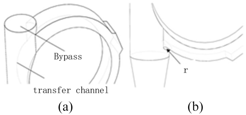
Device improvements: (a) with supplemental air channel and (b) with rounded corners on the lower left corner.
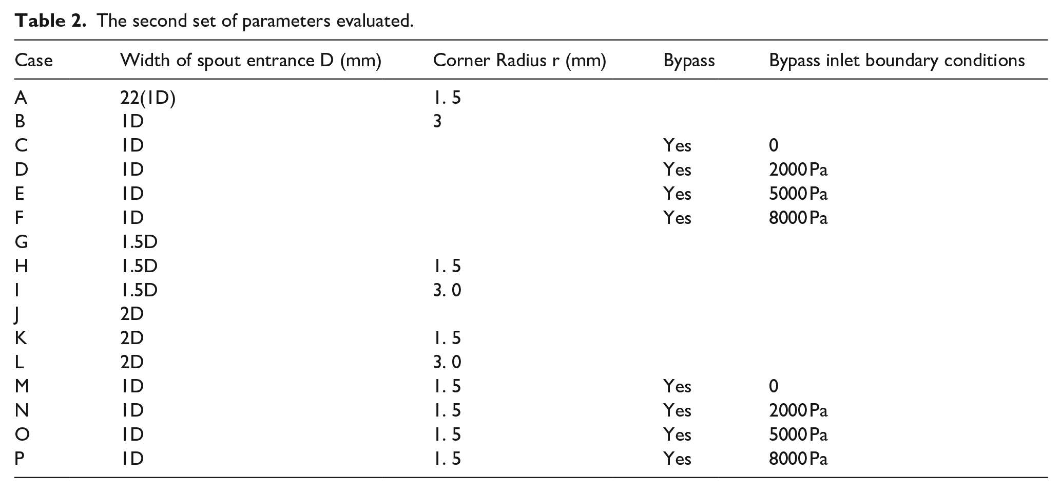
The different sets of parameters evaluated are presented in Tables 1 and 2. In Table 1, there are four different nozzle outlet diameters, nozzle lengths, felting roller speed and felting roller inner diameter. Table 2 illustrates the modification of the transfer channel to reduce unwanted transfer channel inlet vortices. The remaining parameters remain unchanged in accordance with the provisions of Case 2.
Initial set of parameters evaluated.

The second set of parameters evaluated.
Initial boundary conditions: the roll opening speed is 8000 r/min, clockwise, the nozzle outlet is −5 Pa and the inlet absolute pressure is set to 101,000 Pa. Initially, supplemental air channels and circular inlets were not considered. All walls have considered the non-slip boundary conditions. All simulations were performed using ANSYSFLUENT version 19. 0.
Governing equations and turbulence models
For simplification, fibers are not introduced into the simulation. Due to the small size of the carding unit, the time required to complete a complete carding process is very short (less than 0.1 s), so heat transfer is ignored. And the maximum Reynolds number of the carding unit is very high. The current situation is Re = 60,297. The Lin et al.
16
paper mentions that Re ⩾ 64,000 airflow must be considered as turbulent flow. Viscosity is the measure of internal friction force between molecules when liquid is moved by external force. Viscosity is an attribute of fluid, and different fluid values are different. The kinematic viscosity represents the measurement of the internal friction force of the liquid flowing under the action of gravity, and its value is the ratio of the dynamic viscosity to its density at the same temperature. Because this model belongs to the fluid dynamics model only related to air circulation, this model only involves air and yarn. Therefore, in the air and fiber viscosity is an important part. In summary, this article assumes that the airflow during eruption and combing device is Turbulence, viscosity, incompressibility and isothermal properties. The turbulence control equations are reduced to continuity and momentum equations. The system should be closed via turbulent model characteristic equations. For the current research, the


ρ is the fluid density and u is the velocity vector. Ψ represents a generic variable. Γ is the diffusion coefficient and S is the general source term. The source term S is a generalized quantity that represents the sum of all other items in the unsteady, convection and diffusion terms that cannot be included in the governing equation. u, v, and w are generic variables Ψ in the x, y, and z directions, respectively. Momentum diffusion coefficient Γ can be expressed as effective viscosity


Grid independent test
The entire computational domain is a hybrid-grid of structured hexahedral mesh and unstructured tetrahedral mesh. The overall grid and some zoomed views are shown in Figure 3. Near the solid boundary, especially near the felting roller and the rotating wall, the mesh density is particularly high. In fact, we considered three different grid densities. For each grid, the same boundary conditions are used. The number of grids for each type of grid is 1225,807, 2,515,477, and 5,640,469 respectively. Figure 3 shows the results of measuring different grids and the zoomed view used to evaluate the pressure and velocity distribution in the grid transmission channel, along the central axis of the transmission channel (A-A) and through the transmission channel diameter (B-B). The results are shown in Figures 4 and 5.

Positions used to compare the different grid results and zoom views of the grid used.

(a) Relative pressure and (b) velocity magnitude along the transfer channel central axis, A–A.

(a) Relative pressure, (b) velocity magnitude, and (c) tangential velocity across the rotor central diameter, B–B.
Figure 4 shows the speed of the three grids along the center line of the transmission channel. When the number of grids is 100 W, the grid results fluctuate greatly. When the grid reaches more than 200 W, the grid results tend to be stable. Figure 5 illustrates the relative pressure and tangential velocity of B-B in the nozzle, which clearly shows that the values obtained from the coarse mesh do not achieve the required accuracy. Once the grid exceeds 2 million grids, the result has nothing to do with the number of grids. When 3 million grids are used, the results obtained are slightly different from those obtained when 2 million grids are used. However, with an i5-2.5GHz computer the computation time required was 48 h for 3 million grids and 31 h for 2 million grids. Since the results obtained are almost the same and the required computation time is 2 million meshes, which is a short computation time, 2 million meshes are used for all simulations.
Experimental test platform construction
In order to further verify the proposed results, the simulation results are compared with the experimental results. Figure 6 is the test bench system used for measurement. The test bench consists of an LED high-precision flash tachometer, an MF5712 flowmeter, a control cabinet and a single-carding-jet wool spinning unit. The actual speed of the felting roller is measured by a flash tachometer, and the nozzle is connected to a flow meter through a hose to ensure the measurement principle of “the first ten and the last five” to measure the outlet flow.

Test rig scheme and experiment equipment.
To ensure the accuracy of the experiment, the experiment is carried out under normal operating conditions. In order to improve the accuracy of CFD verification. After several experiments, the outlet pressure was fixed at −5 Pa. The aim was to compensate for deviations between simulated and experimental results.
As can be seen in Figure 7. When the rotation speed is too low or high, the simulation and experimental results show a big deviation. This phenomenon caused the authors to think about the outlet pressure of the nozzle and the speed of the stinger roll. It may be due to the following reasons: when the rotational speed is low, the air being sucked from the feed inlet is already sufficient, reducing the eddy currents caused by insufficient air and therefore the flow rate is higher. When the speed reaches 8000 rpm, the speed has already begun to be unstable during actual operation, and the measurement accuracy is low, so there is a large deviation between the simulation and the experimental results. Since the rotation speed is basically 7000–8000 rpm in actual production, and the average deviation of the simulation at this stage is basically 2.66467%, this article believes that the deviation of the volume flow change of 2.66467% can prove the accuracy of the simulation.

(a) Comparison of simulated pressure and experimental results and (b) the deviation of E and S. E: experiment; S: simulation.
Results and discussion
Main general flow characteristics
As the barbed rollers rotate in the carding box, the entire carding box becomes a negative pressure zone (see Lin et al. 16 ). The size and shape of the transfer channel inlet can cause eddy currents to be generated on one side (see Figure 8). Vortexes at the inlet of the transfer channel can significantly affect the internal fiber and parallel channel movement, as they reduce the exit mass flow and the fibers coming off the felting rolls tend to curl when in contact with the vortex. The focus of this paper is on how the parameters defined in Tables 1 and 2 affect the airflow characteristics inside the combing box.

Flow line in plane z = 0 mm in case 2. A-A: central axis of the transmission channel; B-B: through the vortex.
Influence of nozzle outlet diameter
This section focuses on the effect of the nozzle outlet diameter on the flow characteristics and possible internal vortices.
Figure 9(a) shows the airflow velocity in the Y direction at the nozzle exit (B-B in Figure 8). The highest velocities on the wall and the relatively stationary flow in the center suggest that most of the fibers escape from the fiber separation zone (X) to the right of the transport channel entrance, rather than from the central region. Because the aerodynamic force at the center of the channel entrance is very small, the vertical component of the velocity here is close to zero, and it is difficult to overcome the friction and centrifugal force components of the fiber. The centrifugal force will cause the fiber to rotate with the felting roller again.

(a) Velocity distribution along the vertical direction and (b) mass flow rate at different outlet diameters.
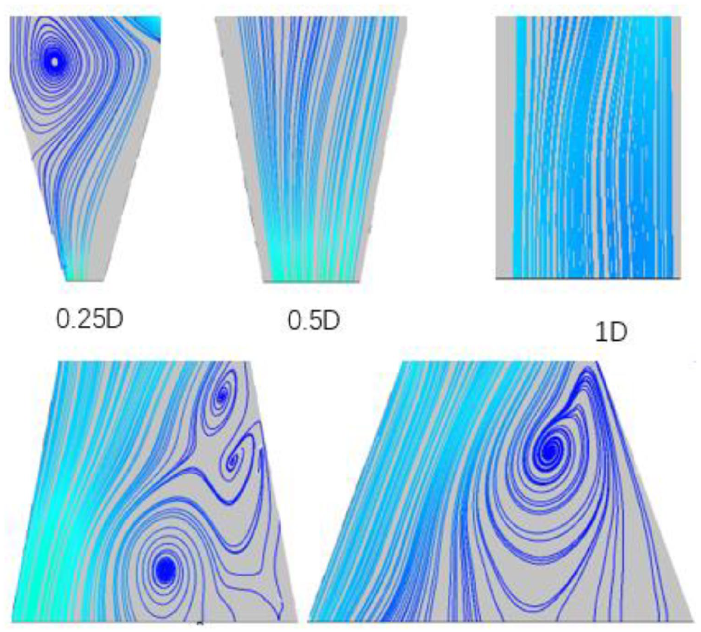
In order to better show the streamline diagram, Figure 10 adds 0. 25D as the velocity streamline of the reference group airflow in the nozzle. It can be seen that when the outlet is small, A vortex appears to the left of the transmission channel, which increases as the length of the transfer channel increases. It can be seen from Figure 9(a) that when the diameter of the nozzle outlet is 0. 5D, a small vortex appears on the left side of the conveyor channel, causing the main flow to move slightly to the right. These turbulences not only increase the likelihood of fiber bending, but also reduce the effective width (i.e. the width of the cross-section containing the forward flow), which can lead to a deterioration in yarn properties. In addition to this, they also slightly reduce the mass flow through the transfer channel, as shown in Figure 9(b).
Different size of nozzle exit, to produce the eddy current in the nozzle.
As can be seen in Figure 9(a), an increase in the nozzle outlet diameter leads to an increase in the maximum flow rate of the Vortex to the right of the nozzle inlet, all the way up to 1D (i.e. 22 mm). However, when the length of the transfer channel is further increased, both the maximum velocity and mass flow rate of the stream decrease. To further research the phenomenon, Two main parameters are considered in this paper. The first is the positive vortex, which occurs in short lengths of transmission channels and gradually disappears as the length of the transfer channel increases. This explains why the flow velocity and mass flow rate increase when the nozzle outlet diameter increases from 0.5D to 1D. It is the disappearance of this particular vortex that is responsible. Shear stress is the second parameter. By further increasing the outlet diameter of the nozzle, the flow rate and mass flow rate will decrease. However, since there are no positive vortices, it can be determined that the flow is driven by shear stress and that the shear stress increases with increasing length.
From Figures 11 and 12, it can be concluded that when the diameter of the nozzle outlet is 0. 5D–1D, the mass flow rate reaches the maximum. The smaller nozzle exit diameter will create a vortex on the left side of the nozzle inlet, which has a greater impact on the mainstream airflow and tends to promote fiber entanglement.

Speed flow diagram for different transmission channel lengths.

Mass flow rate at different transmission channel lengths.
The influence of transmission channel length
In this section, the effect of nozzle length on the flow characteristics of the model is investigated, as well as the possible fiber behavior inside the model.
The velocity in the y-direction at the inlet of the transfer channel (line B-B in Figure 8) is given in Figure 11. The velocity is maximum near the wall, while the flow is relatively stationary at the center. This indicates that most of the fibers escape from the fiber separation zone (X) to the right of the transfer channel inlet rather than from the central region. This is due to the small aerodynamic forces at the center of the channel inlet, where the vertical component of the velocity is close to zero and is unlikely to overcome the components of fiber friction and centrifugal forces, which tend to drag the fibers tangentially along the felting roll.
To better understand the flow behavior, Figure 11 shows the velocity flow line along the transfer channel. It can be seen that a negative vortex appears to the right of the transfer channel entrance, decreasing with increasing transfer channel length. These vortices not only reduce the effective width (i.e. the width of the cross-section containing the forward flow), but also increase the possibility of fiber buckling, leading to a deterioration of the yarn properties. In addition, they affect the mass flow rate through the transfer channel, as shown in Figure 12. The decrease in the mass flow rate to the rotor will increase the fiber transmission time through the transfer channel. This will increase the risk of fiber collision with the wall, thus reducing the fiber configuration.
As can be seen in Figure 11, the maximum flow rate of the main stream located to the left of the inlet of the transfer channel decreases as the length of the transition channel increases. This result may be caused by two partial effects. The first one is the negative vortex on the right side that decreases as the length of the nozzle increases. Shear stress is the second parameter to be considered, which has a secondary effect. Further increasing the nozzle length decreases the flow rate, but the mass flow rate increases only slower but still increasing because of the greater vortex influence compared to shear.
From Figures 11 and 13, it can be concluded that the maximum mass flow rate is reached when a transfer channel length of 50 mm is used. Therefore, in this paper, the nozzle length of 50 mm is considered more favorable for fiber straightening.

Flowline diagrams in different transmission channel lengths.
The influence of open roll speed
The size of the vortex on the left side of the transfer channel decreases as the speed of the stinger roll exceeds 8000 r/min, see Figure 14. As the rotation speed of the roller increases, the maximum vortex tangential velocity will first decrease and then increase, which indicates that the vortex rotation speed and intensity may first decrease slightly and then increase slightly. There is a risk of fibers becoming entangled here leading to negative effects.
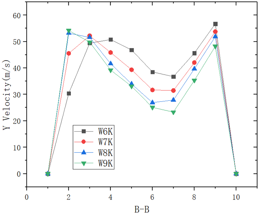
Velocity distributions at the sections B–B as a function of opening roller speed.
Ratio of the average inlet velocity

(a) Ratio of the average velocity
In Figure 14, as the speed of the barbed roll increases, the speed
Influence of the inner diameter of the perforated roll
There are four different felting roller diameters: 50, 55, 63, and 70 mm. The remaining parameters remain unchanged, as shown in Table 1-Cases 2, 11, 12, and 13. The effect of the increase in the diameter of the felting roller is similar to that of the rotation speed, both of which produce an increase in the tangential speed. Although there are expected similarities, when comparing the flow characteristics of Figures 14 and 16, On the right in Figure 16, as the diameter of the embroidery rollers increases, the maximum flow velocity keeps decreasing, and the vortex on the right side keeps on Decrease until it disappears. When the diameter further increases, a vortex is generated on the left side of the nozzle inlet, which squeezes the effective flow channel to the right, and the maximum speed of the Y-axis was dropped. This result is also evident in Figure 17, while a similar trend can be seen in Figure 12. The maximum velocity along the Y-axis to the left of the nozzle inlet decreases as the rotation speed of the stinger roll increases. This opposing effect may be due to the positive vortex flow generated to the left of the channel inlet.

Velocity distributions at the sections B–B as a function of opening roller internal diameter.

Vortices generated at the transfer channel inlet for different opening roller speeds.
As shown in Figure 16, a reduction in the diameter of the barbed roll leads to an increase in the size and intensity of the vortex on the right side of the channel. It can be seen from Figure 17 that when the diameter is 63 mm, the mass flow rate fluctuates smoothly, and when the diameter is increased to 70 mm, the mass flow rate drops suddenly. The turbulence generated in the fiber separation zone leads to this result, as shown in Figure 18. Therefore, it is not advisable to use a roller size that is too small or too large in diameter. Considering production efficiency and yarn performance, a diameter of 63 mm may be the most ideal choice.

Eddy currents at the entrance to the transmission channel for different internal diameters.
Circular air supplement channel and different nozzle inlet diameter
This chapter studies three different inlet widths. The initial case is Case B, and the entrance width is 22 mm. The other two corresponding cases, G and J, are 33 and 44 mm respectively. Each air inlet width box uses three different corner radii r, which are 0, 1.5, and 3 mm.
Figure 19 shows all flow diagrams with respect to inlet width W and fillet radius r. For initial working conditions (r = 0 mm), as the width of the entrance of the conveying channel increases, the main vortex on the right side of the entrance of the conveying channel increases. When the width of the nozzle reaches 44 mm, a second vortex appears in the fiber separation zone. As mentioned earlier, it is critical to protect the fiber separation area from turbulence that can cause fiber clogging, accumulation, and a reduction in the usable area of the inlet. Therefore, it is recommended to use a small channel for yarn feed width to obtain high-quality yarn.
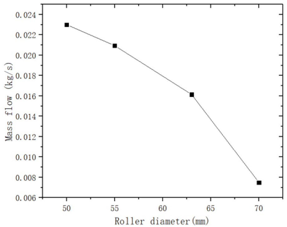
Mass flow rates for different barbed roll inner diameters.
When the fillet on the right side of the nozzle entrance is r = 1.5 mm, both W = 22 mm and W = 44 mm are not good, and the mass flow rate is also greatly reduced. Although W = 33 mm is still poor in quality, the mass flow rate is still small. The increase in amplitude indicates that rounded corners have a certain positive effect on W = 33 mm. When the fillet radius is further increased to 3 mm, the main vortex on the right side of W = 22 mm weakens, the vortex on both sides of W = 33 mm decreases, and the mass flow increases significantly. Comparing Figures 20 and 21, W = 33 mm is ideal the result of. The higher the mass flow rate, the greater the amount of fiber delivered out of the spout. In this way, more fibers can be transported. In addition, yarn quality is improved if turbulence can be reduced to a minimum. Based on the above analysis, in theory, if the outlet size of the conveying channel and the nozzle inlet size can be guaranteed to be the same, the original case (W = 22 mm, r = 0mm) is the most ideal working condition. However, considering that the detachable nozzle is fixed by side screws at this stage, it will cause the nozzle to shift and deform. Therefore, the nozzle inlet size needs to be larger than the conveying channel outlet size, so W = 33 mm and Among W = 44 mm, Case L (W = 33 mm,r = 3 mm) is a more advantageous choice.

Vortex generated in the channel as a function of inlet width and radius of entry angle.

Mass flow rates for different inlet angle radii.
In short, the fiber separation zone must be protected from vortices. When the nozzle inlet width reaches 44 mm, a second vortex appears in the fiber separation zone and this vortex is more intense compared to the others. Therefore, to obtain a high quality yarn, a smaller nozzle inlet width should be used.
The effect of bypass
Adding a supplemental air channel at the top of the conveying channel is another method that may help reduce the intensity and size of the vortex. In this section, 2000, 5000, and 8000 Pa are respectively set as three different bypass inlet pressures. When the bypass inlet is at atmospheric pressure, no additional energy supply is involved in this particular case.
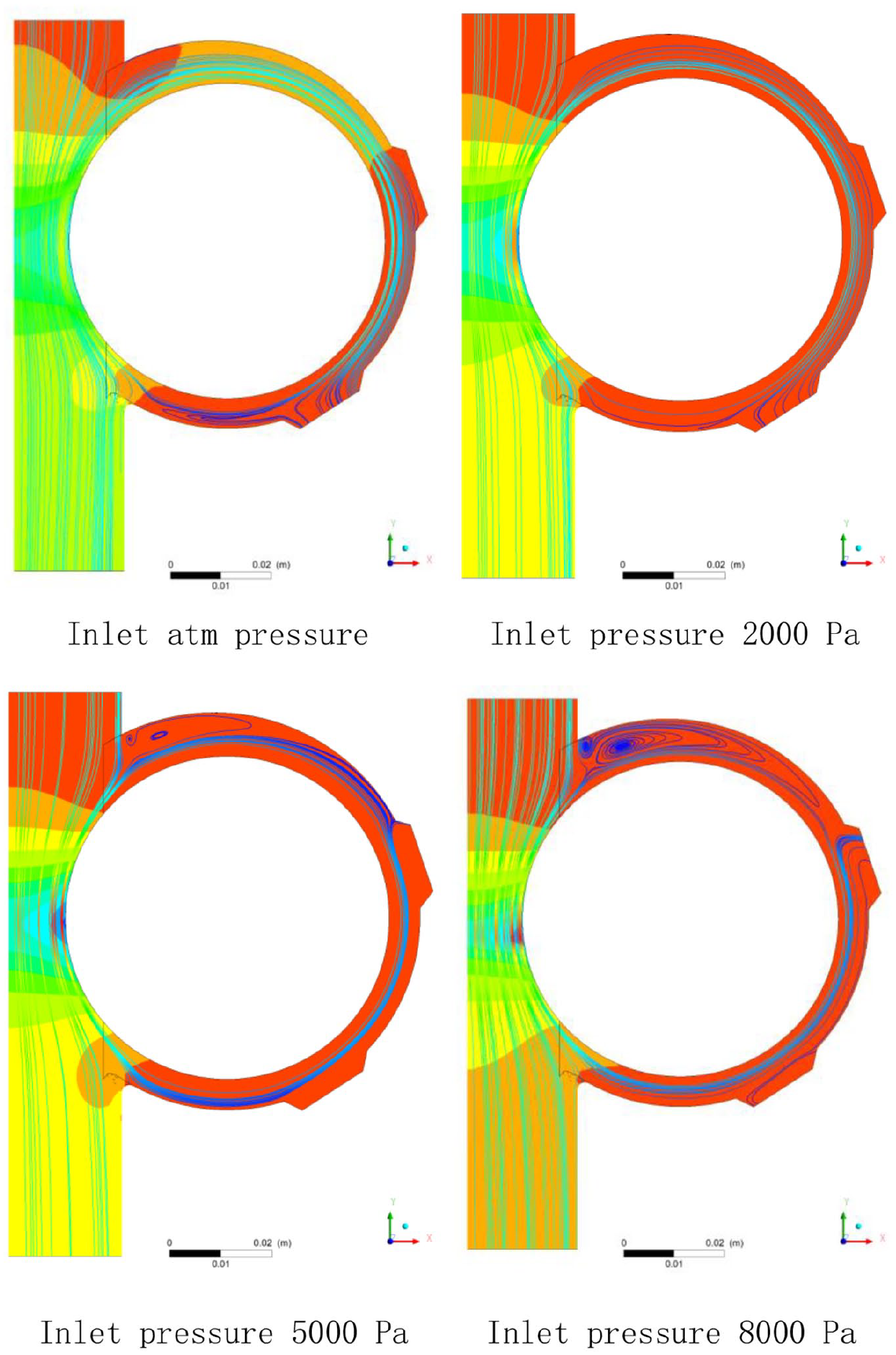
Figure 22 shows four conversion channel flowlines including three pressures and inlet atmospheric pressure. In all cases, the introduction of the bypass results in fewer main vortices to the left of the channel entrance (see Figures 16 and 22). When the bypass inlet pressure increases from atmospheric pressure to 2000 Pa, the main vortex on the right side of the nozzle inlet gradually decreases. But when the inlet pressure of the bypass increases from 2000 to 5000 Pa, the countercurrent area under the rotation of the felting roller increases, and the main vortex on the right becomes larger again. A positive vortex appears on the left side of the bypass, which may be caused by the following reasons: As the air enters the bypass at a lower velocity, the rotating airflow from the stinger rolls combines with the airflow entering the bypass to create a stronger airflow into the channel. If the bypass air pressure increases sufficiently, the airflow into the bypass will cause the main airflow to be diverted toward the rotating area of the stinger roll, creating a positive vortex low pressure field downstream. Figure 21 shows that the airflow enters a wide area from a narrow rotating flow field, causing the air pressure in the transfer channel to be lower than the air pressure in the rotating area, thus resulting in a new positive vortex at the bypass inlet. Conveying channel, and the air flow velocity of the air supply channel is slightly lower than the speed of the licker-in rotation zone. The same conclusion can be drawn by referring to the vortex on the left side of the nozzle (operating conditions J, K, L). When the bypass inlet pressure increases from 5000 to 8000 Pa, the countercurrent zone and the main vortex in the area under the rotation of the felting roller decrease until they disappear, but the area above the rotation of the felting roller appears a countercurrent area. The main reason for the occurrence of the countercurrent zone is that the excessive inlet pressure causes the airflow velocity difference between the air inlet channel and the felting roller to be too large, which causes the airflow of the rotary part of the felting roller to return.

Effect of different bypass inlet pressures on inlet eddy currents in the transmission channel.
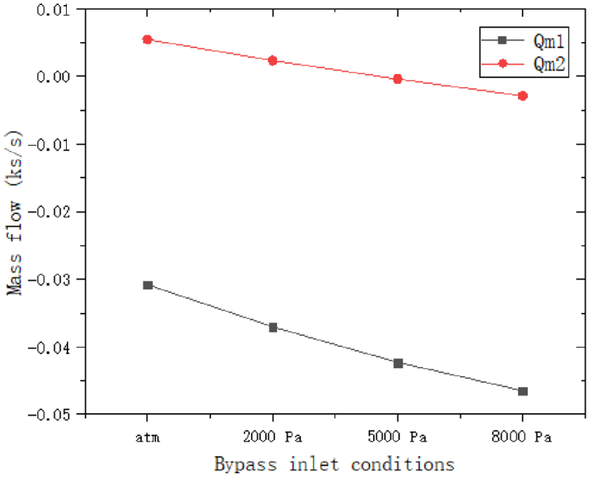
In summary, adding an inlet pressure of 2000 Pa to the bypass inlet will cause the eddy currents to largely disappear everywhere in the chamber, with the highest total mass flow rate (in Figure 22). In addition, the use of bypass improves the overall mass flow.

Transmission channel outlet mass flow and bypass inlet conditions.
Considering the effect of the bypass on the mass flow distribution, the bypass can be added to improve the flow line of the flow channel. The total mass flow rate at outlet
Fillet conversion channel inlet angle and bypass
Inlet angle and bypass for rounded corner conversion channels
In order to take full advantage of the inlet angle and bypass of the rounded corner changeover channel, a new changeover channel design combining the rounded corner and bypass (see Figure 2(b)) is given in this section with four different bypass inlet pressure boundary conditions calculated for 2000, 5000,8000 Pa and atmospheric pressure.
From Figure 24, the main vortex on the left side of the nozzle inlet disappears compared to the case without rounded corners. This indicates that the use of rounded corners to convert the channel inlet angle and bypass can improve the airflow streamlines within the chamber. When the bypass inlet pressure is atmospheric pressure, vortexes appear in the lower part of the felting roller. When the bypass inlet pressure exceeds 5000 Pa, vortexes appear on the upper part of the secondary roller. When the bypass inlet speed increases to 2000 Pa, all eddy currents are eliminated, and the entire streamline becomes quite smooth, providing an ideal environment for the fiber.
Flow diagram after use of inlet rounding and bypass.
The mass flow distribution is shown in Figure 25 and Table 3. When the bypass inlet pressure increases from atmospheric pressure to 2000 Pa, the inlet mass flow decreases, the outlet flow increases, and the vortex disappears in the lower half of the licker-in rotation zone. But when the bypass inlet pressure continues to increase above 5000 Pa, the feed inlet changes from air intake to air output and vortexes appear in the area above the rotation of the felting roller. The main feeding method of the feed inlet relies on the rotation of the felting roller to generate negative pressure to suck the fibers into the carding box, so the feed inlet must be under negative pressure. In order to ensure that the fiber enters the combing box smoothly, with as few eddy currents as possible and as much outlet mass flow as possible in the box, this paper considers that the bypass pressure of 2000 Pa is the optimal solution.
The second set of parameters evaluated.

Transfer channel exit mass flow rate.
Conclusion
In this paper, a three-dimensional CFD model of the combing section of a single-combed air yarn machine is developed. The influence of geometrical and spinning parameters on the airflow characteristics in the detachable nozzle is investigated and a new and improved method is proposed to reduce the eddy currents generated in the transfer channel.
The vortex generated in the transmission channel, the rotation area of the felting roller, and the entrance and exit of the nozzle are obstacles to fiber straightening. In the case of obtaining the minimum vortex and the maximum mass flow, it is recommended that the ratio of the inlet and outlet of the nozzle is maintained between 0.5 and 1. Taking into account the yarn performance and system production efficiency, the roll speed is 8000 r/min, the nozzle length is 30 mm, and the diameter is about 63 mm is an ideal choice.
To weaken the vortex on both sides of the nozzle inlet, by adding a left fillet, using a bypass or both. The main vortex disappeared by adding the fillet on the left corner. If the bypass inlet is set properly, the strength and area of the vortex will decrease rapidly, when the bypass is introduced. The combined design of the fillet and the side channel makes full use of these two concepts, and the proposed channel modification plan can improve the spinning quality.
Research Data
sj-rar-1-jef-10.1177_15589250221121843 – Research Data for Optimization analysis of combing box for air yarn based on computational fluid dynamics
Research Data, sj-rar-1-jef-10.1177_15589250221121843 for Optimization analysis of combing box for air yarn based on computational fluid dynamics by HaiFeng Fang, HanLin Sun, Qun Liu, Rui Liu and MingQiang Wang in Journal of Engineered Fibers and Fabrics
Footnotes
Declaration of conflicting interests
The author(s) declared no potential conflicts of interest with respect to the research, authorship, and/or publication of this article.
Funding
The author(s) received no financial support for the research, authorship, and/or publication of this article.
References
Supplementary Material
Please find the following supplemental material available below.
For Open Access articles published under a Creative Commons License, all supplemental material carries the same license as the article it is associated with.
For non-Open Access articles published, all supplemental material carries a non-exclusive license, and permission requests for re-use of supplemental material or any part of supplemental material shall be sent directly to the copyright owner as specified in the copyright notice associated with the article.