
Abstract
Continuous production of conductive hydrogel fibers has received extensive interests due to their wide application in strain sensors. In this paper, we report on the fabrication of continuous alginate/polyaniline/graphene hydrogel fibers by the in situ polymerization and wet spinning methods. The obtained hydrogel fiber with good flexibility, high water absorbability (11.37 g/g), proper resistivity (220 Ω·m ) and stable resistance changes at both low strain (10%) and high strain (20% and 50%) could be used as a working strain sensor for a wearable human movements monitor. The conductive alginate/polyaniline/graphene hydrogel fiber shows highly sensitive, flexible, and recoverable (90% retention after five cycles) properties when monitoring palm, elbow, and knee movements. This kind of hydrogel with high elasticity and high sensitivity provides a possibility for the preparation of electromechanical sensors.
Introduction
Strain sensors have been developed for sensing physical movement of human beings, which is widely used in healthcare, rehabilitation, and human-machine interfaces.1,2 The flexible strain sensors made of conductive polymer composites, which are enabled to convert mechanical deformations to electrical signals, have received significant interests due to their good electrical properties and soft mechanical properties.3–8 Conductive polymer hydrogels, a type of novel hydrogels which organically combine hydrophilic matrix and conductive medium, show insights and opportunities in flexible electronic devices due to their excellent properties such as high water absorbability, biocompatibility, and electrochemical performance.9,10 Zhang et al. 11 polymerized acrylated adenine and acrylated thymine to fabricate an ultra-stretchable wearable hydrogel strain sensor with double layer, which was applicated in human motions detection, such as finger, wrist, neck, and knee joints.
Alginate-based conductive hydrogela have been widely studied in biomedicine, flexible electronics, and cell engineering, due to their good biocompatibility, low toxicity, and low cost. 12 For example, Hou et al. 13 prepared alginate nanofibril/graphene oxide/polyacrylamide nanocomposite hydrogel, which applied as a high-performance strain sensor with high gauge factor (GF = 4.2), wide workable range (0.02%–2000%), fast response time (~2.5 s), and long-time stability. Khodami et al. 14 synthesize a double network hydrogel based on poly(acrylic acid) and sodium alginate, which exhibited a repeatability (>3000 times) during multiple bending and straightening of the finger smaller than 5%. Compared with bulk hydrogels, fibrous hydrogels are long, thin, and flexible, which means they can be easily weaved to three-dimensional complex constructs.15,16 Alginate fibers have become well established due to their ion-exchange and gel-forming abilities. He et al. prepared a sodium alginate/graphene oxide fibers using wet spinning method. The maximum tensile strength and Young’s modulus of the fibers increased from 0.32, 1.9 to 0.62, and 4.3 GPa, respectively, at 4 wt% GO loading. 17 At present, alginate hydrogel fibers are widely used in the fields of drug release, wound coating, tissue engineering, and so on. 18 However, there is little literature on alginate hydrogel fiber used as flexible sensor. Based on this, we want to fabricate flexible alginate-based hydrogel fibers with electrical conductivity and good electromechanical properties.
In this work, by in situ polymerization aniline (An) in alginate (SA) hydrogel during wet spinning, a composite hydrogel fiber with high stretchability is demonstrated, which can serve as strain sensor for wearable devices. SA is very suitable for making conductive hydrogel fiber. On one hand, it can form hydrogel fibers through wet-spinning in the presence of divalent cations (like Ca2+), due to ionic cross-linking via calcium bridges between the l-guluronic acid residues on adjacent chains. On the other hand, it is an ionic conductive gels with large stretchability, good transparency, and high conductivity. Polyaniline (PANI) is a highly conductive polymer, however, low solubility and difficulty in fabrication have limited its applications.17,19 Introducing PANI into the hydrogel matrix might be an effective method to form a stable conductive hydrogel with semi-interpenetrating network structure. 20 The formation occurs by in situ polymerization of aniline monomer, previously loaded inside the SA matrix. In order to enhance the electrical conductivity and the compatibility, graphene is also used to reinforce the hydrogel fibers. The structure and the morphology of the conductive hydrogel fibers are characterized by Fourier-transform infrared spectroscopy, X-ray diffraction and scanning electron microscopy. And the swelling performance, electricity performance and the electromechanical property of the conductive hydrogel fibers are studied, which provide a support for the large scale preparation of conductive hydrogel fiber.
Experimental
Materials
Sodium alginate (SA, viscosity: 200 ± 20 mpa.s) and aniline (An) were purchased from Aladdin Biochemical Technology Co., Ltd (Shanghai, China), and used as received. Ammonium persulfate (APS, 98%), graphite powder (625 mesh), sulfuric acid (H2SO4), phosphoric acid (H3PO4), potassium permanganate (KMnO4), hydrogen peroxide (H2O2, 30%), and hydrochloric acid (HCl, 30%) were obtained from Sinopharm Chemical Reagents Co., Ltd (Shanghai, China), and were analytical. Calcium chloride(CaCl2) was supplied by Zhejiang Zhongxing Chemical Reagent Co., Ltd. Hydrazine hydrate (HI, 80%) was obtained from Shanghai Lingfeng Chemical Reagent Co., Ltd. All other reagents were analytical and used as received.
Preparation of SA/PANI/GO conductive hydrogel fibers
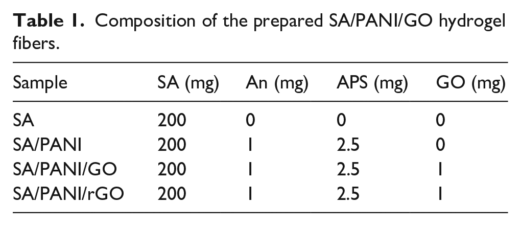
Graphene oxide was prepared in the lab according to the reference. 21 SA/PANI/GO hydrogel fibers were prepared by the combination of in situ oxidation polymerization and wet spinning method, in which a calcium chloride solution (5 wt%) was used as a coagulation bath. In a typical run, 0.1 mg/mL GO aqueous suspension was obtained by ultrasonic treatment 2 h, and then 200 mg SA was added and stirred constantly for about 12 h to form an even SA/GO solution. After that, 1 mg An and 2.5 mg APS were added to the above solution and a ternary mixed solution obtained. The solution was squeezed through a syringe at the speed of 15 mL/h and drawn into the coagulation bath rotating at the speed of 10 r/min at room temperature. The spun fibers were collected and immersed in deionized water for 24 h. To obtain composite fibers with different ratios, a series of solution with different concentration of the raw material was prepared following the same procedure, as shown in Table 1. SA/PANI/rGO hydrogel fiber was obtained by the reduction of SA/PANI/GO by HI steam.
Composition of the prepared SA/PANI/GO hydrogel fibers.
Characterization
The prepared hydrogel fibers were freeze-dried for the morphological observation of SA/PANI/GO fiber by Scanning electron microscopy (SEM, Hitachi S-4800, Japan). Before the observation, the samples were first coated with gold for 1 min using a sputter coater (Desk-II; Denton Vacuum).
A Thermo Nicolet NEXUS 470 Fourier-transform infrared spectrometer (FTIR, USA) was utilized to investigate FTIR spectra of SA/PANI/GO hydrogel fibers. FTIR spectra of samples studied were carried out with KBr powder in the range of 4000~500 cm−1 region.
Roman spectra were obtained with a ThermoFisher DXR2xi Raman spectrometer operating at 633 nm with a power 5 mW.
The crystal structures of the hydrogel fibers were analyzed by X-ray diffraction (XRD Bruker, D8 Advance, Germany). Cu Kα radiation (λ = 0.154 nm) was used under voltage of 40 kV and current of 40 mA at room temperature. The scanning range was 2θ = 5°–60°.
The swelling ratio (SR) of the hydrogel fibers was calculated according to the following equation: SR = (Ws − Wd)/Ws; where Ws was the mass of the hydrogel fiber in the swollen state and Wd was the mass of the dried hydrogel fiber, respectively. Triplicate measurements were performed for each sample and the average result was used.
A 2010 multimeter (Keithley, America) was used to measure the electrical conductivity of the SA/PANI/GO hydrogel fibers, by two probes were placed on the specimens (length of 10 mm), and the electrical resistivity was calculated by the following equation: ρ = R × S/L; where R is the electrical resistivity of the fiber (Ω), L is the distance between the two electrodes (mm), and S is the cross-sectional area of the fiber (mm2). Five samples were measured for each fiber.
The strain-electrical properties of fibers were performed by measuring the resistance change during the strain with a SANs CMT400 tensile testing machine, and the strain rate was 50 mm/min. A total of 10 samples were measured for each fiber.
Results and discussion
Preparation and characterization of SA/PANI/GO hydrogel fibers
The wet-spinning process of hydrogel fibers is shown in Figure 1(a). During the precursor solution of hydrogel (I) was spun into Ca2+ coagulation bath, An rapidly polymerized into PANI in the present of APS (II), and alginate rapidly formed an ion-crosslinked fiber by Ca2+ (III). Hydrogel fibers were readily fabricated using a simple solvent displacement (Figure 1(b)). As shown in Figure 1(c), more than 5 m hydrogel fiber could have been collected during the wet spinning, and the fibers could be easily knitted into a various of textile, which shows the potential for wearable strain sensor.
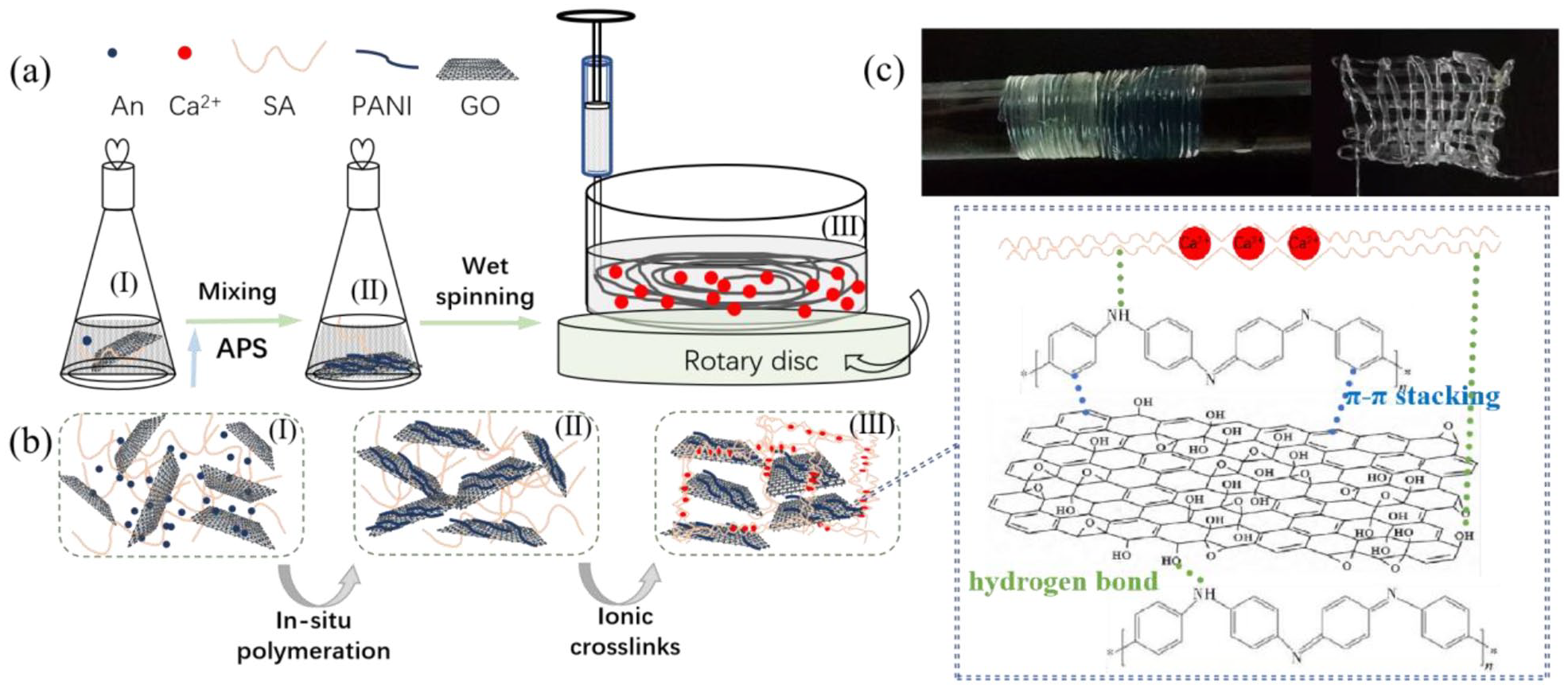
(a) Schematic illustration preparation of the SA/PANI/GO hydrogel fibers, (b) the structural evolution at the different stages during spinning, and (c) photographs of a long single fiber collected on a glass rod and hydrogel fiber.
FTIR spectroscopy was used to confirm the functional groups in the composite hydrogels as shown in Figure 2(a). For FTIR spectrum of SA hydrogel fiber, the peaks at 3430, 1637, and 1389 cm−1 are attributed to the stretching vibration of O–H, the asymmetric and symmetric stretching vibration of COO-groups, respectively.22,23 For SA/PANI hydrogel fiber, compared with SA, a new characteristic peak can be observed at 1042 cm−1, representing C–N stretching vibration peak in PANI.24,25 In conclusion, the SA/PANI composite hydrogel fiber not only has obvious characteristic absorption peak representing alginate, but also has several characteristic peaks representing PANI, which indicates that PANI is indeed in situ polymerized in SA/PANI composite hydrogel fiber. For SA/PANI/GO hydrogel fiber with GO, the peaks appear at 3447, 1740, 1387, and 1063 cm−1 belong to the stretching vibration of O–H, stretching vibration of C=O, bending vibration of O–H and symmetric stretching vibration of C-O, which are from GO. 26 For SA/PANI/rGO hydrogel fiber, the absorption peaks at 3447, 1740, and 1387 cm−1 due to O–H stretching vibration, C=O stretching vibration and O–H bending vibration are obviously weakened. The acquired results indicate that GO is successfully reduced to rGO by HI.

(a) FTIR spectra, (b) Raman shift, and (c) XRD curves of the SA, SA/PANI, SA/PANI/GO, and SA/PANI/rGO hydrogel fibers.
Except FTIR, Raman spectroscopy is an effective method for characterization of carbon composite, as shown in Figure 2(b). For SA hydrogel fiber, the strong peak located at 2913 cm−1 attributed to the stretching vibration of –CH2. The Raman spectrum of SA/PANI hydrogel fiber is basically the same as that of SA, but the peak at 2913 cm−1 is slightly weakened. SA/PANI/GO and SA/PANI/rGO hydrogel fibers displayed two intense peaks at ~1350 and ~1600 cm−1, corresponding to D band and the G band, respectively. Compared with the SA/PANI/GO, the ID/IG ratios change from 1.06 to 1.01 of SA/PANI/rGO hydrogel fiber, suggesting that the content of disordered and defective carbon structures decreased upon the reduction of GO. 27
The XRD is shown in Figure 2(c). The diffraction peaks at 15.9° and 22.4° correspond to the “egg-box” structure of alginate in all samples. In addition, there is a weak diffraction peak at 42.1° as its amorphous structure. 28 There is no new diffraction peak of SA/PANI, but the characteristic peaks are weaker than that of SA, which may be attributed to the damage of the order structure of SA chains by the interactions between alginate and polyaniline. 29 The strong diffraction peak at 22.7° is assigned to the crystallization of GO, indicating the ordered arrangement of GO sheets in the SA/PANI/GO and SA/PANI/rGO hydrogel fibers along the axial direction. 30 It can be found that the original diffraction peak at 16.9° of SA/PANI/GO hydrogel fiber becomes weaker than that of SA/PANI/rGO hydrogel fiber, which may be due to the deformation of hydrogen bond formed between the –OH group of SA and the –NH2 group of PANI with the –COOH of GO. 31 The diffraction peak at 16.9° becomes sharper after the reduction of GO into rGO, which might be on account of the destruction of hydrogen bond between rGO and PANI and SA. 32 The results indicate that alginate is successfully cross-linked by Ca2+, and that there is PANI and GO in semi-interpenetrating polymer network hydrogel fibers.
The hydrogel fibers feel flexible when touched. The surface and the cross-section morphologies of the freeze-dried hydrogel fibers were observed by SEM measurements, and their SEM images are presented in Figures 3 and 4. It can be seen from Figure 3 that surface morphologies of SA and SA/PANI hydrogel fibers are uniform, smooth and compact. Compared with the surface morphologies of SA and SA/PANI hydrogel fibers, the surface morphologies of SA/PANI/GO and SA/PANI/rGO are rough, and there are wrinkles on the surface of hydrogel fibers which might be the aggregated GO sheet. These results indicated that a small amount of PANI will not affect the arrangement of alginate in the length direction. And when GO added into hydrogel, the different shrinkage between alginate and graphene sheet may lead to the rough surface of SA/PANI/GO and SA/PANI/rGO hydrogel fibers during the spinning process. 33

SEM micrographs of the surface of the freeze-dried: (a) a′ – SA, (b) b′ – SA/PANI, (c) c′ – SA/PANI/GO, and (d) d′ – SA/PANI/rGO freeze-dried hydrogel fibers.

SEM micrographs of the cross-section of the (a) a′ – SA, (b) b′ – SA/PANI, (c) c′ – SA/PANI/GO, and (d) d′ – SA/PANI/rGO freeze-dried hydrogel fibers.
The cross-section of the hydrogel fibers show a typical microporous morphology with interconnected micropores. The internal pore structure of SA/PANI hydrogel fiber is finer than that of SA hydrogel, and PANI particles can even be seen on the walls. This is mainly due to their different cross-linking mechanisms. Besides the metal coordination between alginate chain and Ca2+, there is also hydrogen bond interaction between the amino group of polyaniline and the carboxyl group of alginate in SA/PANI hydrogel fibers. Therefore, the network structure of SA/PANI hydrogel fiber is denser than that of SA hydrogel. The network structure of SA/PANI/GO and SA/PANI/rGO hydrogel fibers changed significantly compared with SA and SA/PANI samples. The cross-section of SA/PANI/GO and SA/PANI/rGO hydrogel fibers show larger pores and the thicker walls, indicating that alginate formed a complex structure by wrapping the GO sheets. The larger and more irregular pores of SA/PANI/rGO composite hydrogel fiber may be due to the destruction of interactions between them, such as hydrogen bond between polar groups of graphene nanosheets and –NH2 of PANI, coordination of Ca2+ ions with edge of oxygen-containing groups and the cardinal plane of GO nanosheets. 28
Swelling property
The swelling ratio is an important physical property of hydrogels. As shown in Figure 5, the SR values are about 7.02 and 6.79 for SA and SA/PANI hydrogel fibers, 11.37 and 10.42 for SA/PANI/GO and SA/PANI/rGO hydrogel fibers. Pure SA and SA/PANI hydrogel fibers show lower SR, while SA/PANI/GO and SA/PANI/rGO show a higher SR. This is attributed to a lager pores and looser networks as seen in the SEM images, which could absorb more water molecules in the networks. Comparing this with a reported SR data for sodium alginate/carboxyl-functionalized graphene composite hydrogel (45.6%), the SR values was much higher (1137%) for SA/PANI/GO hydrogel fiber. 34 Generally, the increase of water content will reduce the strength of the conductive hydrogel to some extent, but the appropriate water content will greatly increase the tensile and flexibility of the material. 35

Swelling ratio of the hydrogel fibers.
Electrical conductivity
The electrical conductivity of the hydrogel fibers were measured and the results were shown in Figure 6. The pure SA hydrogel shows the resistivity of 401 Ω/cm, and the resistivity of SA/PANI hydrogel fiber decreased rapidly to 222 Ω/cm. With the reducing GO to rGO, the resistivity declined from 220 Ω/cm to 120 Ω/cm of SA/PANI/GO and SA/PANI/rGO. This indicates that electrons transfer through PANI and GO and ions transfer through the alginate networks, so the resistivity decreases. The conductivities were 0.45 S/m of SA/PANI, 0.50 S/m of SA/PANI/GO and SA/PANI/rGO, respectively, which are higher than that of PVA/SA composite hydrogel (0.30 S/m) 36 and PANI-SA hydrogel (0.10 S/m). 37 Hence, the SA/PANI/GO hydrogel fiber possess a favorable conductivity.

Electrical conductivity of the hydrogel fibers.
Electromechanical property of the hydrogel fibers
This conductivity feature enables the characterization of the stability and sensitivity of the hydrogel fiber sensors using the strain dependence of electrical resistance. The resistance change in the hydrogel fiber was recorded by applying a multimeter and measuring the resistance through two electrical contacts on the fiber. The water content of SA hydrogel fiber and SA/PANI hydrogel fiber samples used for testing were similar and they were 702% and 679%. The water content of SA/PANI/GO and reduced SA/PANI/rGO hydrogel fiber samples were similar, and they were 1137% and 1042%. As shown in Figure 7(a), pure SA fiber shows a relatively higher tensile strength (10.32 MPa) and elongation (176%), the SA/PANI fiber displays a lower tensile strength and elongation at break with 7.27 MPa and 153%. This is maybe due to destruction of SA crosslinking point by PANI chains. The tensile strength and elongation at break of SA/PANI/GO and SA/PANI/rGO hydrogel fibers are 11.90 MPa, 149% and 10.36 MPa, 154%, respectively. It can be seen that the addition of graphene makes up for the decline in mechanical properties caused by the addition of PANI to a certain extent.

(a) Tensile strength and resistance of the SA, SA/PANI, SA/PANI/GO, and SA/PANI/rGO under strain and (b) linear relation curves of the resistance change (R/R0) with strain 0%–50% and (50%–100%).
During the longitudinal drawing of fibers, the resistance of the hydrogel fibers increase until the fracture of the fibers (Figure 7(a)). Three different stages are observed in the curve of resistance versus tensile strain. In stage I (<50% strain), the fibers show a slight increase in the resistance, which could be attributed to a balance between the resistance increasing caused by conductive networks slippage and the resistance decreasing induced by lateral compression. In stage II (50%–100% strain), the modulus of the fibers become higher and the resistance show an approximately linear increase, which corresponds to about 200% of the initial resistance, possibly due to the resistance change being dominated by the slippage of conductive networks. In stage III (>100% strain), a sharp increase in resistance is observed and finally reached infinity, when the fiber is broken, due to the permanent loss of electrical contact between conductive components. 38 In detail, the resistance of SA increased from 10.37 to 61.14 kΩ, when the fiber fractured (at a strain of 187%). The resistance of SA/PANI increased from 5.81 to 55.99 MΩ, when it reached the maximum strain (157%). The initial resistance of SA/PANI/GO is 2.64 MΩ and it reaches 38.05 MΩ at the maximum strain value (148%). The resistance of SA/PANI/rGO increases from 3.96 to 40.82 MΩ, when the fiber is broken (at a strain of 158%).
The resistance change (R/R0), where R and R0 are the resistance and the original resistance of the hydrogel fiber, respectively, could be used to evaluate the electromechanical property of the hydrogel fiber. If strain sensors with high linear response could facilitate the calibration process and improve the signal accuracy and reliability. 39 As shown in Figure 7(b), the R/R0 of the hydrogel fibers exhibits a good linear correlation in stage I (under 50% strain) and in stage I (50%–100% strain), which due to the good elasticity of the hydrogel fibers. As a result, the hydrogel fibers show excellent electromechanical property.
Table 2 is the data of average tensile strength, elongation at break and Young’s modulus of four hydrogel fibers. SA/PANI/GO hydrogel fiber has the best mechanical properties, it is due to the mechanical enhancement effect of GO nanosheets, and the synergistic cross-linking effect of Ca2+ ions with –COOH in GO and –COOH in alginate. The strong interactions between GO and polymer chains facilitate load transfer. 40
Diameter and mechanical properties of the hydrogel fibers.

The stable resistance changes at both low strain (10%) and high strain (20% and 50%) were further investigated by performing cyclic stretching and releasing (set to 5 s) operations to the hydrogel fibers. As seen from Figure 8, before stretching, the resistance of the hydrogel fibers is the minimum, and the resistance reaches the maximum when it is stretched to a certain strain value. The signals show repeatability due to the good recoverable tensile property of the hydrogel fibers, the physical and electrical state of the fiber can be almost completely restored. Even at 100% of the test strain value, the sensory signal of the fiber shows highly consistent characteristics, which indicates that the SA hydrogel fibers have high sensitivity over a wide working range. The gauge factor ((R − R0)/R0) was comparable to those of previously reported hydrogels (Table 3).41–46 It can be seen this SA/PANI/GO hydrogel fiber has a wide sensing range with an ideal sensitivity and linearity.

Time-dependent resistance change of the hydrogel fibers during six stretching-releasing cycles with different strains (10%, 20%, and 50%).
Previously reported gauge factor values of hydrogel sensors.

Because the hydrogel fiber strain sensor has excellent scalability, it has a wide range of work to monitor different human movements. The SA/PANI/GO hydrogel fiber was mounted onto various body parts for evaluating its detecting performance on body movements in real-time by detecting resistance changes, as shown in Figure 9. The results show that the electrical signals are stable and obvious in the whole detection process, whether in the process of small deformations or large deformations, indicating the good sensing properties of the SA/PANI/GO hydrogel fiber and showing promising potential for the application of flexible sensor.
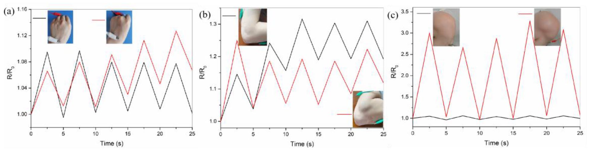
Application of SA/PANI/GO as a wire-shaped sensor in (a) palm, (b) elbow, and (c) knee motions.
Conclusion
In this paper, a series of conductive hydrogel fibers with a semi-interpenetrating polymer network was successfully fabricated by wet spinning. During the wet spinning, aniline was polymerized in situ of sodium alginate solution. The results showed that SA/PANI/GO and SA/PANI/rGO hydrogel fibers exhibited excellent water uptake (up to 1137% and 1042%) than that of SA (702%) and SA/PANI (679%) hydrogel fibers. And the resistivity of SA/PANI/GO and SA/PANI/rGO hydrogel fibers are 220 and 120 Ω/cm, respectively, which are lower than that of SA and SA/PANI hydrogel fibers, an improvement on the electrical conductivity. During the longitudinal drawing of fibers, good linear relationships were observed between strain (<50%, 50%, and 100%) and resistance change (R/R0) of the prepared hydrogel fibers. As a strain sensor, the hydrogel fibers showed sensitivity and repeatability during six stretching-releasing cycles with different strains (10%, 20%, and 50%). In addition, SA/PANI/GO hydrogel fiber showed a fast response speed and good repeatability as a wire-shaped sensor in palm, elbow, and knee motions, indicating this hydrogel fibers is a flexible sensor presents great promise in artificial flexible electronics.
Footnotes
Declaration of conflicting interests
The author(s) declared no potential conflicts of interest with respect to the research, authorship, and/or publication of this article.
Funding
The author(s) disclosed receipt of the following financial support for the research, authorship, and/or publication of this article: We gratefully acknowledge the financial support from the National Natural Science Foundation of China (52101385). Zhejiang University Student Science and technology innovation activity plan project (2021R417025).