
Abstract
The rod presser foot and needle bar driving mechanism of the embroidery machine cannot achieve accurate parking time and position at high speed, which limits the development of high speed embroidery machine and make the quality of embroidery decline. Aiming at solving this bottleneck problem, the characteristics of the embroidery machine presser foot and needle bar driving mechanism based on analyzing the mechanism kinematics is developed. These characteristics and influences of each linkage parameters on the presser foot parking time and position are analyzed. Six main parameters are selected to optimize by using the complex method. Taking the parking position and linkage parameters as constraints, the parameters of the main linkages was optimized in order to obtain the maximum parking time of the presser foot mechanism. The results show that the optimized parameters is more reasonable and effective, the pause time of the presser foot mechanism is increased by 15.5%, and the parking position of the embroidery machine is at 100° ± 0.5° as required by the technological requirements, which satisfies the requirements of the coordinate movement of the needle bar-presser foot drive mechanism of the high-speed embroidery machine. The study also provides a method reference for the follow-up high-speed embroidery machine research and development.
Keywords
Introduction
At present, double cam-drive is widely used in embroidery machines, and the problem of parking time and position accuracy of combined presser foot and needle bar drive mechanism driven by single cam has not been completely solved. 1 Therefore, the accurate matching of the driving mechanism of presser foot and needle bar has become a bottleneck problem which restricts the development of embroidery machine in structure and technology. As far as the driving mechanism of presser foot is concerned, the function is to ensure the precise cooperation with embroidery mechanism, that is, to press the cloth in time before embroidery and when the embroidery needle is lifted, so as to ensure the quality of embroidery.2–4 It is necessary to ensure that the time required for needle rod to drop needle, prick cloth, and lift needle is less than the time for presser foot mechanism to restart movement, so as to ensure the precise cooperation of embroidery machine.
One solution is to optimize the parameters of the driving mechanism, so as to change the matching relationship of kinematic characteristics and realize the precise matching at high speed. Many scholars have studied the optimization of mechanism. Qin et al. 5 and Thomas et al. 6 took the length of six bar mechanism as the optimization variable by using genetic algorithm to iterate the optimal result. Zhang et al. 7 calculated the relative weight coefficient of each bar based on the hierarchical method, and then combined with genetic algorithm to optimize five bar mechanism. 8 Jorge et al. 9 worked with the Cartesian coordinate system corresponding to the rotary joint of the linkage mechanism to transform the original constrained optimization problem into an unconstrained optimization problem, but the method was more complicated. Li et al. 10 solved the general formula according to the relationship between the design variables and the Fourier coefficients, using the Fourier coefficients of the prescribed path to directly solve the design variables and the synthesis problem of the combined linkage mechanism. It provides a method reference for improving the parking time of presser foot. In addition to the matching relationship between the presser foot and the needle bar movement, another process requirement is to ensure that the embroidery machine stops when the spindle turns to 100° so as to facilitate automatic operation such as thread change and needle change. 11 Combined with ARM9 controller as hardware platform and WINCE5.0 software platform, Qu et al. 12 realized the flow drive design of high-speed industrial embroidery machine spindle control system. Lin et al. 13 improved the stop time precision of embroidery machine by compensating the commutation current and restraining the torque ripple of motor in commutation.
In this study, based on the matching relationship of the core driving mechanism of embroidery machine, the kinematics model of the combined bar of the needle bar and presser foot driving mechanism was established. The parameters related to the output influence of the needle bar and presser foot driving mechanism were analyzed. In order to overcome the short pause time of the presser foot and the insufficient matching with the needle bar mechanism and the poor accuracy, by using the complex method, the main structure parameters were optimize. It also provides a design theory reference for the development of high speed embroidery machine.
Principle of presser foot and needle bar driving mechanism
A schematic of the presser foot and needle bar driving mechanism is illustrated in Figure 1. Take the cam center as the origin to establish the coordinate system as shown in Figure 2. The needle bar driving unit is represented by the solid line, and the presser foot driving unit is represented by the dotted line. O, A, B, C, D, E, G, H, and L are used to represent the hinge point between linkages, lij (i ≠ j, i = O, A, D, E, H; j = A, B, E, F, L) and lijk (i ≠ j ≠ k, i = B, F; j = C, G; k = D, H) are the length of linkages. The principle of the mechanism is as follows: the cam lOA is driven to rotate at high speed which causes the needle bar link lAB to move in a plane, the three-eye-link lBCD to rotate about the hinge point C and the link lDE to move in a plane. Driven by the connecting rod lDE, the needle bar driving mechanism (mE) moves in a reciprocating straight line. At the same time, driven by the needle bar driving mechanism, the presser foot auxiliary connecting rod lFGH rotates about the hinge point G. Driven by the three-eye-rod lFGH and rod lHL, the presser foot driving mechanism(mL) moves in reciprocating linear motion. While mL drives the presser foot to keep the cloth under control, mE drives the embroidery needle to pierce the cloth. While mE drives the embroidery needle to lift, mL drives the presser foot to lift. At each cycle, the rest time of the driving mechanism of the presser foot should meet the time requirements of the needle bar for needle dropping or lifting, that is, it should be greater than the time of the needle bar’s rising and falling and should not be too great to avoid to delay the movement time of the next cycle.
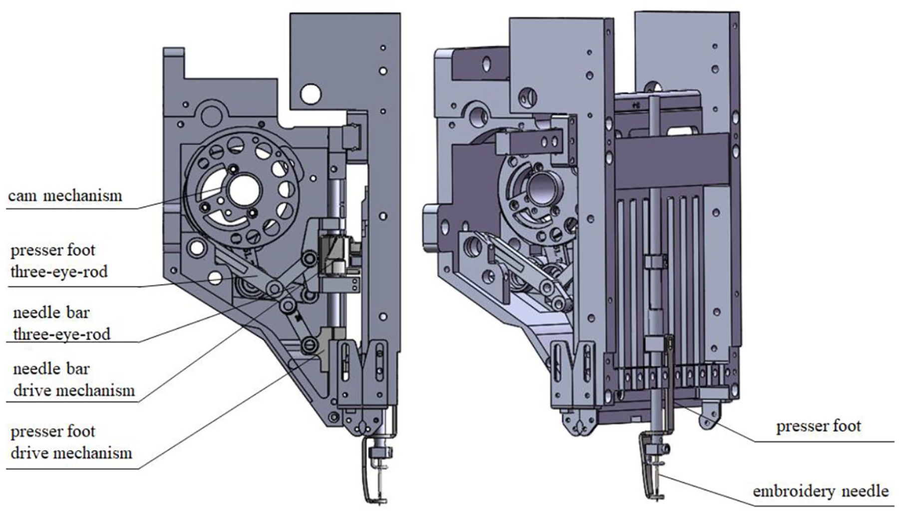
The presser foot and needle bar drive mechanism.

The diagram of presser foot and needle bar driving mechanism.
Kinematic analysis of presser foot and needle bar driving mechanism
Mathematical model of needle bar driving mechanism
The force and torque required in the whole motion chain are transmitted by the cam in the needle bar driving mechanism, which is equivalent to a small crank. The whole mechanism is composed of a four-bar mechanism OABC and a crank slider mechanism CDE, as shown by the solid line in Figure 2. The complex vector method is used to analyze the motion of the four-bar mechanism.
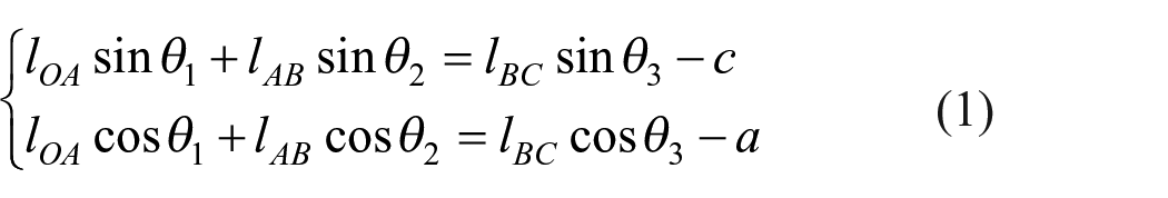
Where lOA is the base circle radius of the cam; lAB is the length of the linkage AB. Other linkage length representations are similar. θi (i = 1, 2, 3, 4) is the angle between the connecting rod and X-axis; a is the horizontal distance from the center of the spindle to the center of the connecting rod lBCD; b is the horizontal distance from the center of the spindle to the center of the presser foot driving mechanism; c is the vertical distance from the center of the spindle to the rotation center of the connecting rod lBCD. From Figure 2, we can obtain the following equation:
where

For the slider crank mechanism, the following equations can be obtained:

where ϕ1 is the angle between lCB and lCD; yE is the vertical distance from the driving mechanism of the presser foot to the rotation center. We can derive the following equations:


The second derivatives of the equations (1) and (4) can be calculated and expressed in a matrix form:

where, ω2, ω3, and ω4 are the angular velocities of the Linkages lAB, lBCD, and lDE respectively; ve is the velocity of needle bar drive mechanism; α2, α2, and α3 are the angular accelerations of the linkage lAB, lBCD, and lDE respectively; ae is the acceleration of needle bar drive mechanism.
Mathematical model of presser foot driving mechanism
The schematic diagram of presser foot driving mechanism is shown in Figure 3. Similarly the following equations can be obtained;

where d is the horizontal distance from the center of rotation G to the center of rotation C; e is the vertical distance. We can derive the following equation:

where

The diagram of the crank slider is shown in Figure 4. The kinematic analysis of the crank slider GHL is carried out to investigate the motion law of the presser foot. We can derive the following equations:


where θ7 is the angle of the linkage lHL; The second derivatives of the equations (8) and (11) can be computed and expressed in a matrix form in order to obtain the acceleration of the needle bar driving mechanism:

where, ω5, ω6, and ω7 are the angular velocities of the Linkages lGFH, lEF, and lHL respectively; vl is the velocity of presser foot drive mechanism; α5, α6, and α7 are the angular accelerations of the linkage lGEH, lEF, and lHL respectively; al is the acceleration of needle bar drive mechanism.

The structure diagram of the multi-link slider mechanism.

Structure diagram of crank slider.
Based on the above analysis, if we assume the main axis speed of 600 rpm and the center O of the cam axis as the origin while considering the displacement curve of the presser foot and needle bar as shown in Figure 5, it can be seen that the presser foot will remain stationary while the main axis rotates between 239° and 319° as shown (Δθ) in Figure 5. Therefore, the existing mechanism cannot meet the requirements of the embroidery process which requires to stop at the position of 100° within ±2° accuracy. According to Figure 5, the parking angle of the original presser foot and needle bar mechanism is 95° (Δθ′ as shown in Figure 5), which cannot satisfy the required angle either.

The presser foot and embroidery needle displacement diagram.
Computer aided analysis platform and optimization of linkage design
Computer aided analysis platform
From equations (6) and (13), we can see that the length of the linkage directly affects the movement of the presser foot and needle bar. In order to easily and intuitively understand the influence of these parameters on the motion law, a computer aided analysis platform was developed, as shown in Figure 6. By adjusting the parameters, the platform can automatically draw the displacement, speed, and acceleration curves of the presser foot and needle bar mechanism, and the pause time of the presser foot mechanism and the parking position of the embroidery machine can be obtained at the same time. Compare the generated curves by changing single or multiple parameters, and six key dimensions are selected for optimization.
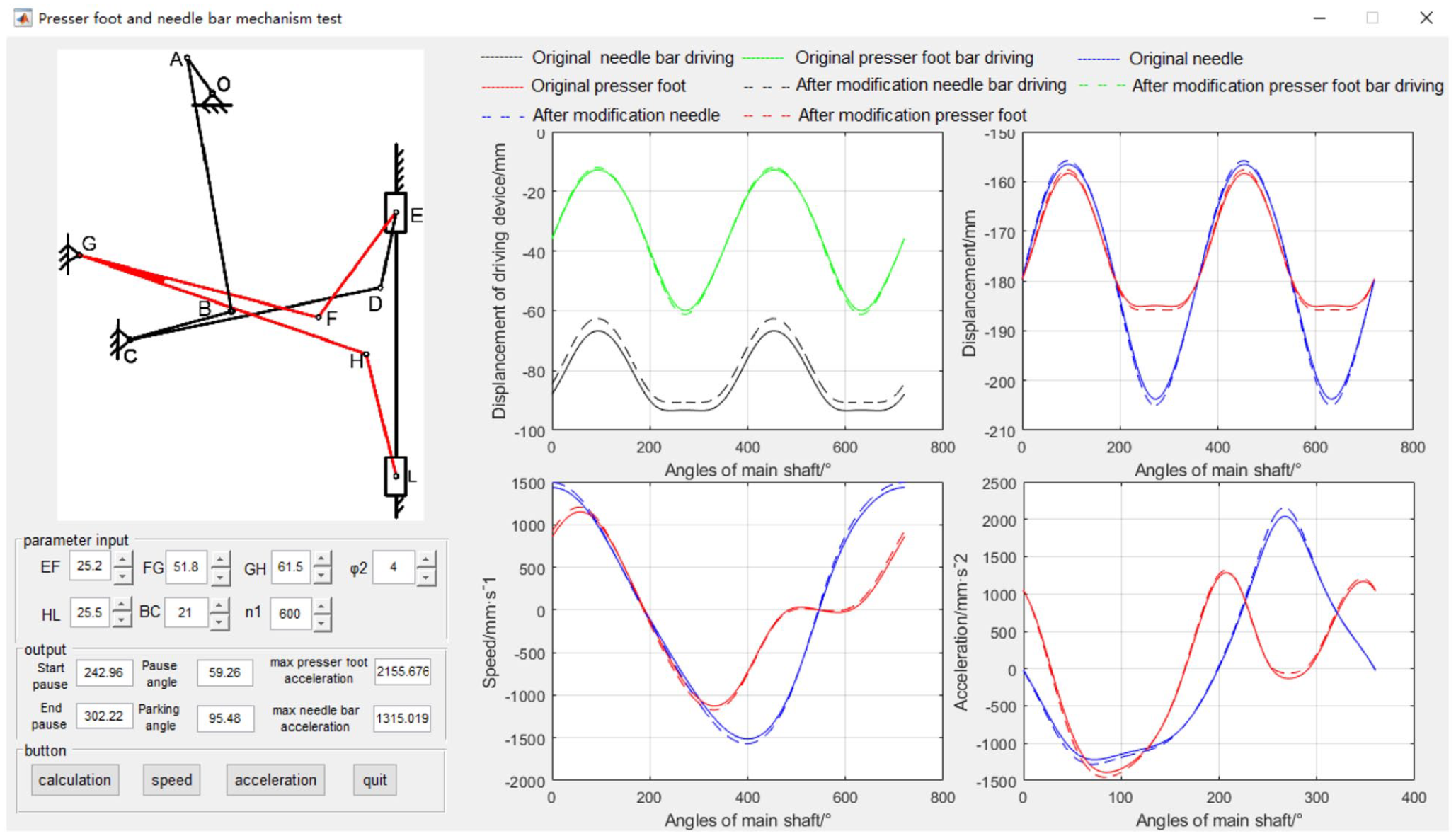
Computer-aided analysis program for the presser foot and needle mechanism.
Optimization principle of complex method
Because the complex method is a direct search method instead of the gradient search method, 14 it has been widely used 15 in material engineering, 16 turbine blade design, electronics, and other fields. 17 It is based on the given N initial conditions to form 2N initial vertices and feasibility check, If the initial vertices are outside the constrained range, as shown in Figure 7(a), the method will make them move closer to the centroid of the feasible point, and then the sizes of the feasible vertices are compared with each other. The initial complex vertex with the largest function value is taken as the bad point, and the centroid of other points are calculated. The bad point is mapped to the centroid, and the generated point is called mapping point. As shown in Figure 7(b), the four vertices of the initial complex shape are X(H) (bad piont), X1, X2, X(L) (optimal point); X(C) is the centroid; X(R) is the mapping point. If the mapping point is a feasible point and the function value is smaller than the optimal point, the mapping point is expanded to generate an expansion point and its feasibility is checcked; if a good mapping point cannot be found, the contraction method can be used to form the contraction point. The details are shown in Figure 7(b). X(E) is the expansion point generated by expanding the mapping point X(R) according to the expansion coefficient ξ, and X(K) can be found by shrinking within the line from X(H) to centroid X(C), where the shrinkage coefficient is γ. Then the generated feasible mapping points (expansion points or contraction points) will replace the bad points to form a new complex. As shown in Figure 8, this iterative process makes the complex shape approach and shrink to the best point until the accuracy is satisfied.18,19
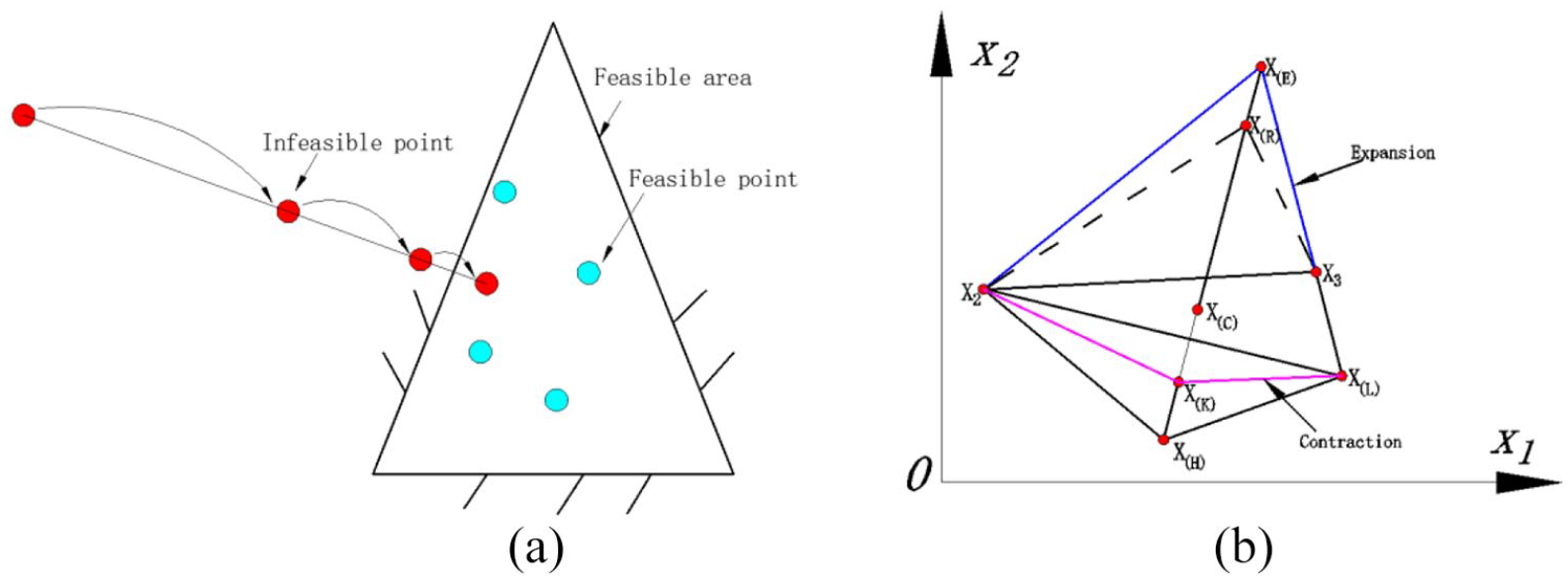
Close, expansion, and contraction operations in two-dimensional design space: (a) close operation and (b) expansion and contraction operations.

The iteration process in the two-dimensional design space.
Selection of optimization parameters
In order to meet the pause time of the presser foot within the specified range, it is necessary to determine the rotation angle of the main shaft when the presser foot drive device remains stationary at the lowest position. Therefore, the objective function can be determined and the optimization model can be established.

where f1 is the relationship function between the displacement of the presser foot driving mechanism and the rotation angle of the main shaft. According to the above equations (6) and (13), the parameters that affect the pause time of the presser foot driving mechanism and the stop position of the embroidery machine can be obtained. Therefore, lEF, lFGH, lHL, and lBC are selected as design variables, which are used to define the variable matrix X:

In fact, the comprehensive problem involves many constraints such as geometric conditions and working space limitation to avoid adverse effects between components. 20 It can be seen from Figure 9(a) that the presser foot and needle bar driving mechanism move simultaneously in the previous period of time. When the presser foot mechanism presses the cloth and keeps still, in order to avoid collision between the moving needle bar mechanism and itself, the distance between the rotation centers of the driving devices should be larger than the minimum allowable size shown in Figure 9(b).

The schematic diagram of driving mechanism: (a) the displacement diagram of the rotation center of the driving mechanism and (b) the structural dimension of the driving mechanism.
In order to prevent collision, it is necessary to limit the distance between the two driving mechanism:

where

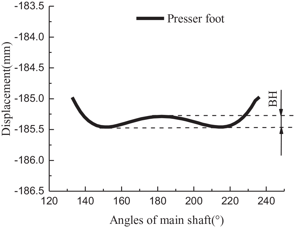
Original parameters presser foot backhaul diagram.
where

where f1′ and f2′ are the relationship between presser foot displacement, needle displacement, and main shaft angle; SP is the angle at which the presser foot remains stationary; D is the position deviation, which is equal to 0.5°; P is the rotation angle of the main shaft when parking. Also need to consider the parameters limit of the linkage:

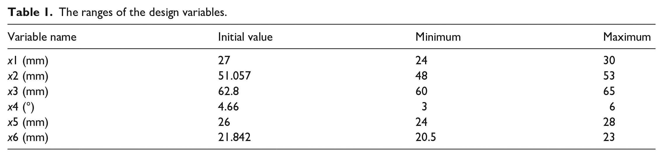
where n and bi are the upper and lower limits of the i-th design variables; ri is the design variable. Considering that the boundary constraints, it is necessary to estimate the possible range of the optimal solution on the basis of the structural parameters of the existing mechanism so as to make the optimal solution as close as possible to the center of the boundary constraint. In this study, A design variable x’ was selected in turn from the design variable
The ranges of the design variables.
After optimization objective function, design variables and constraints are defined, the structural parameters can be optimized. The optimization algorithm is shown in Figure 11. Several parameters of the presser foot and needle bar mechanism were optimized based on the complex method and genetic algorithm. In this method, roulette wheel selection and the best reserved selection are used for reproduction, one-point crossover used for recombination and simple mutation for mutation.

The flow chart of the parameter optimization program.
Optimization results and analysis
The iterative process of the complex method and genetic algorithm is shown in Figure 12. When the number of iterations is 1, the value of the objective function of the genetic algorithm is smaller than that of the complex method. This is because the initial point of the complex method is the original value of each variable, while the genetic algorithm randomly generates an initial population of Nm solutions within the range of the variable before the start of the iteration. Therefore, the initial objective function values of the two algorithms are different.
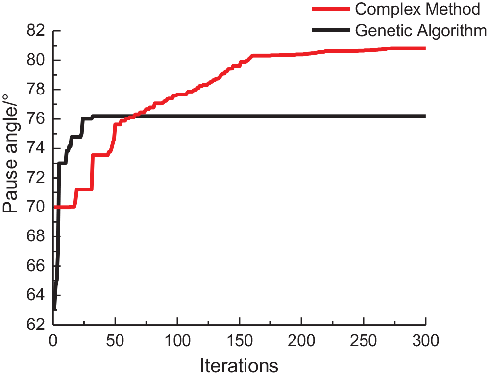
The iterative graph of the complex method and genetic algorithm.
The optimized solutions of the variables after optimization are shown in Table 2.
The variable optimal solution.

As we can see from Figure 12, the convergence speed of the genetic algorithm is faster than that of the complex method, but the genetic algorithm will fall into the local optimal solution. From Table 2, we can see that the pause angle is increased from 70° to 80.82° which is about 15.5%, while that of the genetic algorithm is increased about 8.9%. The problem discussed in this paper focuses on increasing the pause angle, which does not require high convergence speed, thus the complex method has more advantages. The comparison of embroidery needle and presser foot before and after optimization is shown in Figure 13.

The comparison of the embroidery needle and presser feet before and after optimization: (a) displacement curve, (b) speed curve, and (c) acceleration curve.
It can be seen from Figure 13(a) that the parking angle after optimization is 100° and the stop time of the presser foot also meets the working requirements, and the static angle also rises to 80.82°. It can be seen from Figure 13(b) and (c) that the optimized parameter reduce the speed and acceleration of the presser foot at the lowest position, which can prevent the cloth from moving relatively. When moving to the highest and lowest points of embroidery needle and presser foot, the speed and acceleration increase, but the acceleration curve is smooth, which will not produce large impact and vibration to the machine.
Conclusions
The research and development bottleneck of a high-speed embroidery machine is that the motion matching error of needle bar and presser foot driving mechanism cannot meet the needs of the high-speed embroidery process. It is necessary to design the structure parameter relationship from the mechanism kinematics to meet the cycle shortening. In this study, for the core driving mechanism of the high-speed embroidery machine, the combined presser foot and needle bar driving linkage mechanism, based on the establishment of the mathematical model of the kinematics analysis, we select the design variables according to the influence of different components on the displacement curve. Moreover, using the complex method to optimize the component parameters, the goal of the optimization of the coordination relationship under the working requirements of the embroidery machine is achieved.
As a complex mechanism control system, the high-speed embroidery machine not only meets the trajectory matching requirements of the mechanism kinematics level, but also meets the actual working requirements, such as stopping and changing lines, overall size limit, actual design size limit, and other conditions. Besides the academic level, the optimization parameters range of the actual engineering design is limited by these requirements. The complex method can be applied to the mathematical kinematic constraints and physical constraints are combined as complex constraints to carry out multi-objective and multi parameters optimization design, such as increasing the pause time of presser foot and achieving accurate parking, reducing the speed and acceleration during the static period under the condition of reasonably optimizing the structure parameters of parts, and obtaining a satisfactory solution to meet the actual working conditions. At the same time, it also provides a useful theoretical reference for the study of constrained parameters optimization design in other light machinery.
Footnotes
Declaration of conflicting interests
The author(s) declared no potential conflicts of interest with respect to the research, authorship, and/or publication of this article.
Funding
The author(s) disclosed receipt of the following financial support for the research, authorship, and/or publication of this article: This work was supported by National Natural Science Foundation of China (grant number 51975536).