
Abstract
The preforms of three-dimensional (3D) braided composites have a monolithic structure that is braided with high-performance fibers using 3D braiding technology. Compared with traditional laminate composites, braided composites are widely favored because of their superior overall performance and mechanical properties. The capability of fabricating various yarn structures with a flexible 3D rotary braiding method, however, has not been systematically investigated, especially for a variable-section braiding structure. In accordance with the principles of braiding technology and the characteristics of a 3D braiding structure, in this study, we examined a braiding technology for the production of 3D variably shaped cross-section fabric, focusing on three key factors: the topology design of tracks, the arrangement of carriers, and the matrix algorithm of the braiding of variably shaped cross sections. We calculated new kind of structural synthesis approach to a 3D braiding track for a variable section based on the carrier arrangement characteristic method and completed the entire braiding scheme of the variable cross section. In addition, this approach represents an important step toward a simplified understanding of the carrier motion and the operator-independent operation of a 3D rotary braiding machine.
Introduction
Braiding provides an ideal composite material for textile preforms, but the special cross section of braiding is restricted by the braiding procedure of machinery with different cross-section shapes. Thus, by studying historical braiding structures, a more reasonable braiding structure than the existing mechanical braiding structure has been introduced to improve the modulus strength and function of braiding composite materials. 1 In addition, one major limitation of three-dimensional (3D) braiding composites is that the cross section of a preform is determined by different braiding machines. Furthermore, most industrial machines are designed only to braid preforms with invariable cross sections. One important advantage of 3D braiding is that preforms for a composite component with complex geometry can be made with a near-net shape.2,3 In terms of the cross-sectional braiding type, the most common braiding structures with variable sections are circular tables, hyperbolic scanning bodies, drum shapes, and other irregular circular rotating body braiding structures. Many engineering applications, however, such as aircraft rotor blades, aircraft radar, wind turbine blades, and missile shell heat shields, do not involve ISO sectional structural parts with regular shapes, but rather variably shaped cross-section structural parts whose section sizes change along the direction of the length or width. At present, the main method for obtaining a composite with a variable cross section is to first prepare a composite with an equal cross section of the appropriate size and then to carry out machining operations, such as cutting and grinding to obtain the final shape size. Mechanical processing has a significant impact on the properties of composite materials, including serious damage to the reinforced fiber, degradation of the integrity of the structure, and greatly reduced mechanical properties.4–6 Because 3D braiding technology for a variable section can be used for the complete braiding of prefabricated parts without damaging the reinforced fiber, research about this technology is particularly important.
The basic principle of 3D braiding technology is that the number and arrangement of yarns on the chassis of a braiding machine are closely related to the size and shape of the cross section of the specimen. In existing traditional braiding technology, once a particular cross section is selected as the initial braiding cross section, the size and shape of the yarn array will remain unchanged throughout the braiding process, resulting in the same cross-section structure as the original. Xiao et al. 7 achieved the geometric forming simulation of 3D braided prefabricated parts by establishing a mathematical model between the textile process parameters and the geometric structure parameters. Shao et al. 8 analyzed the spatial position of the yarn in a rectangular preform and determined the yarn path through Bezier curve fitting. Kim 9 studied the simulation of the maypole braiding process. Yarn paths were calculated by simulating the relative movement of multilayer horn-gears and numerous spindles in the actual braiding process, and the overbraiding on mandrels with an arbitrary profile was possible. The braiding process determines the microstructure of composites, an important factor affecting mechanical properties. 10 Before the 1980s, braiding was concentrated mainly in the four-step braiding process, gradually leading to the six-step, multistep, and later processes. Subsequently, the two-step method and multilayer interlock braiding technology were developed. After 2000, the 3D rotary braiding machine emerged. Great improvement in the speed of movement quickly made this the mainstream braiding technology. 11 Representative examples include the 3Tex and Herzog machines.12–13 Recently, RWTH Aachen University and the University of British Columbia jointly developed a second-generation hexagon knitting machine, which greatly increased the number of chassis and the amount of yarn. This machine centered on medical applications,14–15 and the 3D braiding equipment featured a variably shaped cross section; however, the track layout had a certain complexity, requiring higher professional standards for operators. In the existing literature, most of the studies provide solutions to specific local problems; the final shape of the cross section of a prefabricated part is achieved through continuous tests in actual production; and a systematic, clear-cut description of the evolution of these machines is lacking. Two recent books by Professor Yordan Kyosev in 2015 and in 2016 introduced the basic principle of braiding and the application field of fabric’ structures. These books also analyzed in detail the principle of the carrier arrangements and the design process of special-shaped cross-section braiding fabric, particularly in relation to 3D rotary braiding.16–17 This information was especially useful for this study.
We proposed a carrier arrangement characteristic (CAC) method to obtain various forms of tracks by splicing the elements of the tracks, such as a “2 × 2 oblique” track, a “484” track, an “∞” track, and a “V” track. The CAC and the repeat involved the position and the number of carriers to avoid a collision between the carriers. We obtained a set of 4 × 4 tracks through the CAC method to prepare braids with variably shaped cross sections. The motion mechanism of the braiding consisted of two parts: (1) the carrier moves into position, and (2) the track changes. We then established the braiding matrix to predict the braiding matrix and the path. The braiding matrix could be carried out to represent all yarn positions. The oblique track not only avoided collision between carriers when they moved along the tracks, but also braided the variably shaped cross-section structure without changing the machine settings, thus allowing designers to braid the variably shaped cross section more easily.
Track structure design
Commonly used track types include the single minimum units (such as a “484” track, “∞” track, “2 × 2 oblique” track, and “V” track), as shown in Table 1. Any track element larger than these minimum track elements can be composed of these minimum track elements spliced together.
Commonly used minimum splice tracks.

For the 484 track type shown in the table, the first 4 represents one horn-gear with four slots, the 8 represents two horn-gears with eight slots, and the second 4 represents one horn-gear with four slots. The 484 track can restrain a carrier’s arrangement characteristics at 4 Full and 4 Empty (f4, e4). Full indicates that there is a carrier in the position of the arrangement, and Empty represents the fact that there is no carrier in the position of the arrangement. The minimum arrangement repeat is 8 (8 = 4 Full + 4 Empty). Thus, the specific arrangement type of the carrier must be 10100101 to avoid a collision between the carriers. Similarly, 4 Full and 4 Empty are also required for the carrier arrangement characteristics in the ∞ track type—that is, when the minimum arrangement repeat is 8 (8 = 4 Full + 4 Empty) and the arrangement type is 10100101, there is no collision between the carriers. The specific form of the 2 × 2 oblique track type is that the track is tilted to decorate, and the oblique angles are 45° and 135°, where 2 × 2 indicates two rows and two columns of the horn-gear with four slots—that is, there are 4 horn-gears (4 = 2 × 2) in total, and the arrangement characteristic of the carriers is 1 Full and 1 Empty. The minimum configuration of its arrangement repeat is 2 (2 = 1 Full + 1 Empty), and the arrangement type of the carriers is 10. Thus, there is no collision between the carriers in the oblique track. The fourth type is the V-shaped track, which requires few carriers. Only when the minimum arrangement repeat of the carrier is 4 (4 = 1 Full + 3 Empty)—that is, when the arrangement form of the carrier is 1000, do the carriers not collide in the V-shaped track. Two or more of the types of minimum track elements shown in Table 1 can be spliced together to obtain a larger track element. The 16 track elements in Table 2 are composed of four 2 × 2 oblique tracks spliced together in various ways. This is called a 4 × 4 braided track unit, and the corresponding obtained splicing points (NoSP) are 0, 1, 2, 3, and 4. The number of splicing points is a statistical outcome of the number of splicing points around the 4 × 4 track unit after the middle splicing position is completed.
4 × 4 units and their NoSP.

(a) There is only one type of 4 × 4 unit (No. 1 in Table 2) and its NoSP = 0.
(b) There are four types of 4 × 4 units (Nos. 2–5 in Table 2) and their NoSP = 1.
(c) There are six types of 4 × 4 units (Nos. 6–11 in Table 2) and their NoSP = 2.
(d) There are four types of 4 × 4 units (Nos. 12–15 in Table 2) and their NoSP = 3; there is only one type of 4 × 4 unit (No. 16) and its NoSP = 4.
Similarly, we spliced together four 4 × 4 track units (No. 8, No. 9, No. 10, and No. 11) to form an 8 × 8 oblique track unit, as shown in Figure 1, where the numbers 1, 2, 3, and 4 in parentheses in No. 8 (1), No. 9 (2), No. 10 (3), and No. 11 (4) represent the order of splicing.

8 × 8 track decomposed into four 4 × 4 track units.
The basic idea behind this splicing principle is that any 3D braiding system (BS) can be regarded as being composed of n tracks connected by m switch cams, and can be written as follows:

where
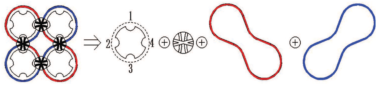
2 × 2 braiding system decomposed into horn-gears, switch cams, and tracks.
The splicing principle of an 8 × 8 track unit is shown in Figure 3. We established the structural analysis and the splicing method of tracks based on a BS unit in accordance with this splicing principle. The general CAR formula is


The jth splicing track.
where fi is the summation of the ith braiding unit, m is the number of braiding units, υ is the number of track loops,
1. Determination of CAC of the braiding unit of Nos. 8–11: according to equation (1-2b), the CAC of each 4 × 4 track unit of Nos. 8–11 is equal:

2. According to equations (1-2b) and (1-3), the number for the first carrier arrangement characteristics of the No. 8 track unit is
3. According to equations (1-2a) and (1-3), the CAC of the subtrack formed by the first (No. 8) and second (No. 9) track units is

4. According to equations (1-2b) and (1-5), the number for the second carrier arrangement characteristics of the No. 8, No. 9, and No. 10 track units is
5. According to equations (1-2a) and (1-3), the CAC of the subtrack formed by the first (No. 8), second (No. 9), and third (No. 10) track units is

6. According to equations (1-2b) and (1-7), the number for the third carrier arrangement characteristics of the No. 8, No. 9, and No. 10 braiding units is
7. Determination of repeat of the 8 × 8 track unit: According to equation (1-2b),

Thus, the carriers of the 8 × 8 track unit are arranged in accordance with 10, and the repeat is 2.
Principle of braiding with a variable cross section
We spliced the 8 × 8 oblique track unit, as shown in Figure 1, using the previously discussed splicing method. This 8 × 8 oblique track unit could be used to braid 3D fabric with variably shaped cross sections. Figure 4 shows the 8 × 8 braiding machine developed by Professor Sun Zhihong of Donghua University. Based on this machine and using the principle of oblique track braiding, we introduced the braiding process of 3D fabric with variably shaped cross sections. In the process of braiding, the role of the horn-gear was to provide power for the movement of the carriers. The switchable cam (switch) shown in Figure 5(d) was provided on the carrier tracks at the junction of each pair of horn-gears, which served to control either the movement of the carriers around the original horn-gear or their transition to the next horn-gear. The advantage of this approach was that any continuous variably shaped, cross-sectional, and complex shape or form of fabric could be achieved with this single machine after a brief prearrangement of the carriers and tracks.
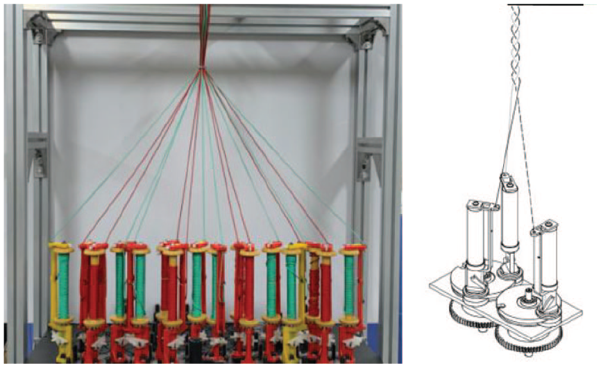
3D rotary braider in the form of 8 × 8 and scheme of rotary braiding.

Motion mechanisms of braiding with variably shaped cross sections and 0 and 1 states of the switch cam: (a) time t0, (b) time t1, (c) time t2, and (d) state of switchable cam.
The motion mechanism of the carrier consisted of two parts: the rotation of the horn-gears and the rotation of the switches, as shown in Figure 5. The motion process is described as follows: At time t0, the carriers moved in their own respective tracks. The red track was marked as the track of line I, and the carrier in this track was marked as the carrier of line I, including the first and third carriers. In the same way, the blue track was marked as the track of line II, and the carrier in its track was marked as the track of line II, including the second and fourth carriers, so that the two closed paths crossed each other, and the yarns intertwined at the intersection point, forming an invariably shaped cross-sectional braiding structure by controlling the switches. When the cross-sectional shape of the fabric needed to be changed at time t1, that is, when the statuses of the switches on the second and fourth positions of the two horn-gears in track I needed to be changed, as shown in Figure 5(b), the value changed from 1 to 0, causing the first and third carriers in track I to move to track II. The status of the initial movement of the carriers was then disturbed, however. To balance the status of the original movement of the carriers at this moment, the status of the switches on the second and the fourth positions reverted to its initial status, and the value changed from 0 to 1, as shown at time t2 in Figure 5(c). The status of the switches at this moment allowed the new specially shaped cross-section fabric to be formed. The braiding process was nonintermittent and continuous high-speed motion by constantly adjusting the status of the tongue-like switches effectively avoided collisions between the carriers in the intersection. Although this mechanism of braiding with variable cross sections was easy to describe in a logical programming language, it was difficult to present with computable mathematical expressions.
Algorithm for modeling arrangement of tracks and carriers
Matrix algorithm design
With the 8 × 8 braiding process as our research object, we used matrix theory and a symbolic operation to model the carrier movement to form a theoretical foundation for further study. We also investigated a braiding matrix calculation method. We predicted the path of the carriers in the 8 × 8 oblique track unit. Finally, we verified the feasibility of the braiding of variably shaped cross sections by establishing the connecting carrier’s walking trajectory and taking the braiding of variably shaped cross sections from the rectangular cross section to the circular cross section as an example.
Tracks I and II in the horn-gear arrangement are shown in Figure 6. The red and blue solid dots indicate a slot with carriers; otherwise, without carriers in the slots. Carriers could be placed at every slot of the horn-gear, but up to half of the slots of each horn-gear could be placed with carriers at the same time, so at least half the positions were needed to transmit the carriers from the adjacent horn-gears. 18

Arrangement of braiding track disk.
By establishing an XOY rectangular coordinate system, as shown in Figure 6, the walking trajectory of each carrier could be predicted. We obtained the walking trajectory of each yarn, and through the interleaving and separation of all yarns, we completed the braiding of the 3D fabric with variably shaped cross sections ranging from rectangular-shaped cross sections to circular-shaped cross sections. To model and analyze the coordinate transformation of the carriers in the braiding process, we introduced the position coordinate matrix A(k) of the carrier and the state matrix S(k) of the switches, as shown in equations (1-10) and (1-11), where K represents the braiding steps. Each element of the matrix A was presented in plural form.

where each element in the 8 × 8 braiding matrix A(k) is expressed as a complex number

where the value of 0 indicates that there was no switch in this position; the value of the other elements is expressed as the complex number

The carrier returned to the starting point after several braiding steps, as shown in equation (1-13)

where T is the motion period of the carrier. The braiding mode of the carrier could be represented by the accumulation of
8 × 8 Braiding matrix model for variably shaped cross section
Matrix A(k + 1) was established after the shape of the cross-section braiding was changed, as shown in equation (1-14):

where
We took the 3D BS process with the carrier configuration of 8 × 8 as an example to show the analytical procedure, for which the unit matrix


Yarn path storage and yarn path table calculation
The motion cycle of the carrier was that the carrier returned to its original position after moving along the track, which was related to the length of the track in which the carrier moved. The position of a carrier determined the position of the yarn in the fabric structure, and we selected the middle position of each unit curve of the track as the characteristic point. Then we stored the corresponding X and Y coordinates in the corresponding track according to the order of the carrier’s movement. Thus, their positions and the corresponding arrangement of the carriers for the rectangular tracks (1–1 to 1–7 and 2–1 to 2–7 shown in Figure 7) were as noted in Table 3.

Initial coordinate positions of the carriers and their walking track diagrams.
Spatial position and carrier arrangement of rectangular track.

The 128 carriers (solid dots) in the 8 × 8 braiding system in Figure 7 moved along their own tracks so that they reached the 128 characteristic points, as shown in Table 3, where they were marked with respect to their initial positions at the initial time t0. Then the locus database of the yarn and the trajectory was established and stored in the 1–128 units.
The carriers started from the initial position shown in Figure 7 and moved along their own tracks from t0 until the next shape of the cross section was needed, as shown in Figure 8, that is, from the rectangular-shaped cross section to the circular-shaped cross section.

Scheme of arrangement from rectangular track to circular track: (a) rectangular track and (b) circular track.
When the cross-section shape of the fabric changed from the rectangular shape to the circular shape according to the mechanism of the motion of the carrier described in Section 3, namely, before the carriers moved to the location of the switch cams, the state of the switch cams in the 20 locations shown in Figure 8(b) had to be changed from 1 to 0. Then we substituted the motion positions of the carriers into equation (1-14) to achieve the braiding of a variably shaped cross section.
According to the described method, we fitted and interpolated the X and Y data for each yarn in the database. Then the interpolated data were stored in the new database. These data were then called using MATLAB software and the yarns were drawn one by one in an image in which yarns on different tracks were defined using different colors. Then the fabric simulation from the rectangular cross section to the circular cross section was drawn, as shown in Figure 9. Finally, using the 3D braiding machine shown in Figure 4, we obtained the 3D braiding fabric with the cross-section shapes ranging from rectangular to circular, as shown in Figure 10, which verified the correctness of our proposed theory.
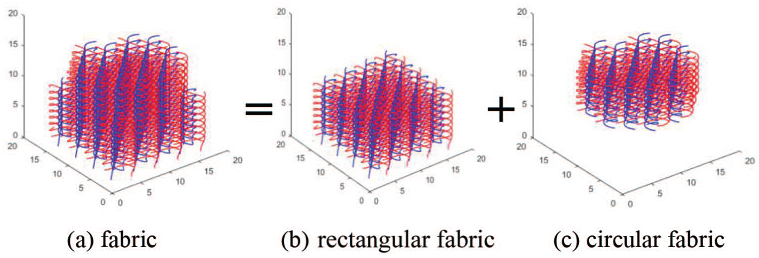
Simulation diagram of the braiding of variably shaped cross sections: (a) fabric (b) rectangular fabric, and (c) circular fabric.

3D fabric of variably shaped cross sections braided by the braider shown in Figure 4.
Conclusions
We proposed splicing principles of the braiding track based on the CAC method of the 2 × 2 oblique track unit. We established the corresponding methods for the track structure splicing of a braiding system that could achieve variably shaped cross-section braiding. We also established the algorithm design for calculating the braiding matrix to depict the movement process of the carriers and the state of the switches. The structural simulation solution and the actual fabric from the rectangular cross section to the circular cross section were achieved. MATLAB software was employed to analyze an example to verify the correctness of the theory we set forth. The results showed that the fabric model established by the tracks based on this method was precise and useful in the actual braiding, and this model could provide a basis for the further research and analysis of the mechanical properties of variably shaped cross-sectional fabric.
Footnotes
Declaration of conflicting interests
The author(s) declared no potential conflicts of interest with respect to the research, authorship, and/or publication of this article.
Funding
The author(s) disclosed receipt of the following financial support for the research, authorship, and/or publication of this article: This work was supported by the National Science Technology Support Plan Projects, “Development of the 3D Circular Carbon Fiber Braiding Machine” (grant number 2011BAF08B03).”