
Abstract
Parabolic antennas, which are wildly used as high-gain antennas for point-to-point communications, need many iterations of design-fabrication-test in parabolic antenna development. However, traditional molding via mechanical processing takes a long manufacturing cycle and high cost. In this paper, a 3D-printed CF/nylon composite parabolic mold for CF/epoxy parabolic antenna is studied. It’s found that the coefficient of thermal expansion (CTE) of 3D-printed CF/nylon composite is usually anisotropic due to the low adhesion between printed layers and the aligned short carbon fiber along the printing trace. Here an inclined mode of 3D printing could uniform the CTE of the antenna mold and solve the problems of large printing steps and the separation of supports and mold occurred in horizontal and vertical modes, respectively. The parabolic mold also reveals high profile precision with a low root mean square (RMS) deviation of 0.14 mm. Utilizing the 3D-printed CF/nylon composite mold, parabolic antenna skin with low surface RMS deviation of 0.16 mm was successfully fabricated by laying CF/epoxy prepreg and curing in autoclave. This research about isotropic and smooth 3D-printed CF/nylon mold may support the low-cost and rapid mold development for microwaves relay links on ground and satellite communication antennas.
Introduction
High-gain and high-directional parabolic antennas are widely used in point-to-point communication such as microwave relay links and satellite.1–3 Parabolic antennas need high profile accuracy to reflect the directional signal to the receiver.4–6 Normally, the traditional forming process of parabolic antenna involves upper and lower metal molds.7,8 However, due to the variant demands of satellite antenna on weight and antenna profile,9,10 satellite parabolic antenna often needs to fabricate a serious of molds when developing a new parabolic antenna. It is important to decrease the antenna developing time and cost by rapid fabrication of molds with low-cost materials.11,12 As a novel manufacturing technology, 3D printing allows designers to rapidly and on-demand fabricate complex geometries and device parts.13–16 Based on the modeling software, the designed parts were sliced layer by layer and the finished products were printed through additive manufacturing.17,18 It has significant advantages in rapid prototypes.19–21 However, the demands of 3D-printed molds are completely different from those of 3D-printed parts.22,23 Besides the demand of mechanical properties, 3D-printed molds also should have high surface accuracy and high thermal stability.24,25 Recently, an acrylonitrile butadiene styrene (ABS) mold was built for composite articular orthoses, 26 in which clay was filled in the inner of mold to decrease the deformation of mold and the surface of printed mold was coated by epoxy resin to decrease the surface roughness. The extra postprocesses highly decreased the advantages of 3D printing rapid molding. There are two ways to shorten mold fabrication process. One is to printing high modulus and low thermal expansion filaments and another is optimization of 3D printing setting such as placement mode and slice mode.
In this paper, 3D printing technology was studied for advanced parabolic antenna mold using the filament of nylon with chopped carbon fiber as the 3D printing materials. We investigated the coefficients of thermal expansion (CTE) of 3D-printed short carbon fiber reinforced composite specimen at various direction and the influence of 3D printing modes (horizontal, vertical, inclined modes) on quality of 3D-printed parabolic antenna mold. By optimizing the 3D printing mode, a composite mold with very low surface deviation of 0.14 mm, which was better than the demand of molding accuracy (surface deviation <0.2 mm), was obtained. Based on the mold, the parabolic antenna skin with profile precision (0.16 mm) was successfully fabricated by laying CF/epoxy prepreg and curing in autoclave. This research may support the low-cost and rapid mold development for microwaves relay links on ground and satellite communication antennas.
Experiment
Materials
A blend filament of nylon 6 with chopped carbon fiber (Onyx, Markforged Inc.) was used as the printed material. Teflon tapes and CF/epoxy prepreg (thickness of 0.08 mm, P9051F-7) consisted of continued carbon fiber and epoxy were used for preparation of CF/epoxy antenna. The continued carbon fiber (M40J-3K) were provided by Toray Industries, Inc. and epoxy resin (BA9913) was from AVIC Composite Corporation Ltd.
Fabrication
Markforged X7 (Markforged Inc.) is selected as the printing system to print composite mold. The printing parameters were set as extrusion temperature of 275°C, slice layering of 0.125 mm and the diameter of nozzle was 0.4 mm. As illustrated in Scheme 2, both the top and bottom included two layers and the triangular filling had a filling density of 55%. The CF/epoxy antenna was prepared by laying of Teflon tapes, CF/epoxy prepreg and vacuum bag and then curing at 135°C and 0.4 MPa for 2 h in autoclave as shown in Scheme 1. The heating rate, cooling rate, pressure in vacuum bag, gas charging pressure were 5°C/min, 10°C/min, 0.008 MPa and 0.3 MPa, respectively.
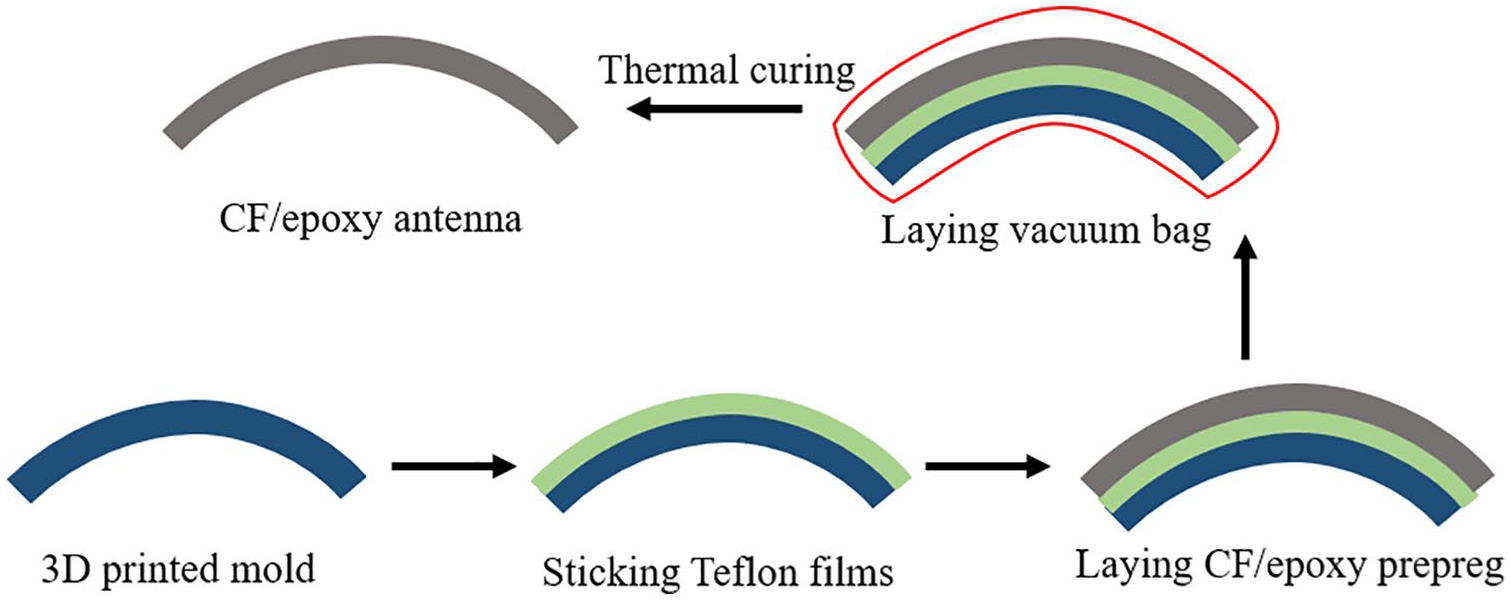
Preparation of CF/epoxy parabolic antenna using 3D-printed mold.

(a) Computer designed and (b) as prepared cross-sectional antenna.
Characterization
Coefficients of thermal expansion of 3D printed materials was determined using dilatometer (Netzsch DIL 402SE). Cross-sectional morphologies of 3D-printed Onyx specimen obtained from the broken specimen after tensile strength tests was observed by a scanning electron microscope (Supra 55VP, Zeiss) at accelerating voltage of 20 kV. 3D profiles of printed mold and CF/epoxy composite antenna were measured by a structured light scanner (ATOS triple scan measurement system, GOM company) and the profile precision was evaluated from the root mean square (RMS) deviation between real measured values of paraboloid and compute designed values.
Results and discussion
Antenna mold with diameter of 200 mm was designed as shown in Figure 1(a). It was consisted of a paraboloid surface and stiffening supporting ribs. The surface accuracy and stiffness of the mold is important to fabricate the composite antenna skin through vacuum-bag and autoclave process. The stiffness of the 3D-printed mold can be easily improved by using strong materials and good design for example, increasing thickness of the mold and adding stiffening ribs to supporting surface. However, the surface accuracy of 3D-printing product is not very high due to the step pattern caused by layer-by-layer stacking process. To find a suitable 3D printing method to provide good surface accuracy, we designed three printing modes to 3D-print antenna mold: horizontal mode, vertical mode and inclined mode (Figure 1(b–f)). For a typical flat structure, the horizontal mode is the most common way to print specimen due to its easy placement. From supported materials generated by 3D-printing software (seen the purple region in Figure 1(c), (e) and (g)), it can be found that less supported materials were used in horizontal mode and there should has inner supports in the mold for vertical mode which were hard to remove. The inclined mode with 30° to the normal direction of printing platform needs more supports, however the supports can be easy to remove with less on the damages on printed specimen. These designed molds with different 3D-printing modes were printed in the Markforged 3D printer with sliding thickness of 0.125 mm at room temperature.

(a) Top and bottom sides of designed paraboloid antenna mold. (b–g) 3D printing process with horizontal mode (b and c), vertical mode (d and e) and inclined mode (f and g) and their supporting marital displayed as purple color (c, e and g).
Here, Onyx filament, a blend filament of nylon with chopped short carbon fiber, was selected as 3D-printing filament for mold printing. With the help of carbon fiber, Onyx has high flexural modulus (3.6 GPa), good flexural strength (81 MPa) and high heat deflection temperature (145°C), while those of nylon were 1.4 GPa, 50 MPa and 41°C, respectively. Meanwhile, Onyx also has low CTE (22.3×10⁻⁶ K-1) with help of carbon fibers, which was similar to aluminum and 1/5 of CTE of nylon 6 (−110×10-6 K-1). Thus, Onyx with the high modules and good thermal stability is a good choice for mold materials. Normally, thick structures were 3D-printed with a certain filling density to increase the fabrication speed and decrease the material usage. To characterize the thermal expansion of 3D-printed Onyx, CTE of the printed samples in three dimensions was characterized. The specimens in x, y and z axis were 3D-printed as an Onyx skin with filling of −45°/+45° Onyx ribs and were shown as schematics in Figure 2(a) and (c). The CTE of specimens in x, y and z axis were tested through length change (Δl/l) at various temperatures, where l0 indicates the initial length of specimen and Δl is the length change of the sample at a certain temperature. Figure 2(b) displayed the length change rate at various dimensions. It showed that the 3D-printed specimens has good linear thermal expansion at different temperature. The CTEs in x and y axis were closed and around 25×10-6 K-1 due to similar structure in layer. However, it is a little higher than the CTE of Onyx block. It could be due to the tinny pores or defects caused by printing process in the specimen (seen in Figure 2(c)). In contrast, the CTE in z axis is 3 times of that in x axis. From the cross-sectional SEM images in Figure 2(d), it was found the printed polymer didn’t fully melt on the under layer and the short carbon fibers were aligned along the printing traces. It caused the high thermal deformation between the layers (z direction) and low thermal deformation in layer (x and y direction) constrained by carbon fibers. The anisotropic CTE of the 3D-printed sample would cause the mold distortion when thermal curing and highly affect the profile accuracy of antenna. Compared to the horizontal and vertical printing mode shown in Figure 1, inclined mode can disperse the thermal expansion at z axis into height and dimeter direction of the paraboloid and could decrease the anisotropic thermal expansion of paraboloid surface.

(a) Schematics of the specimens for CTE measurement. (b) The length change rate in x, y and z directions of 3D-printed specimen at various temperatures. (c and d) Cross-sectional SEM images of 3D-printed specimen with various magnification.
Antenna molds 3D-printed by horizontal, vertical and inclined modes were shown in Figure 3(a) to (f). There were obvious step patterns on the mold printed by horizontal mode, while the molds printed by vertical and inclined modes had smoother surfaces. These step patterns were caused by the limited layer precision of 3D-printing (0.125 mm for a layer) and the inclination of paraboloid profile to z axis. As shown in Figure 3(g), the paraboloid at horizontal mode has high slope to z axis and it can be found large size steps in-between the printed layers. The paraboloid at vertical or inclined mode intended to straight and the surfaces consisted of multilayers (blue strips in Figure 3(g)) was smoother. Another defect on antenna molds printed by horizontal mode is the fusion mark (red circle in Figure 3(b)) at region of beginning and end of the circular path. The molds printed by vertical mode had a separation problem of support and paraboloid surface when 3D-printing the top section of the molds (seen in Figure 3(c) and (d)), which could decrease the printing precision on top section. Inclined mode could well solve the problems of large stepping patterns and lack of support (seen in Figure 3(f)).
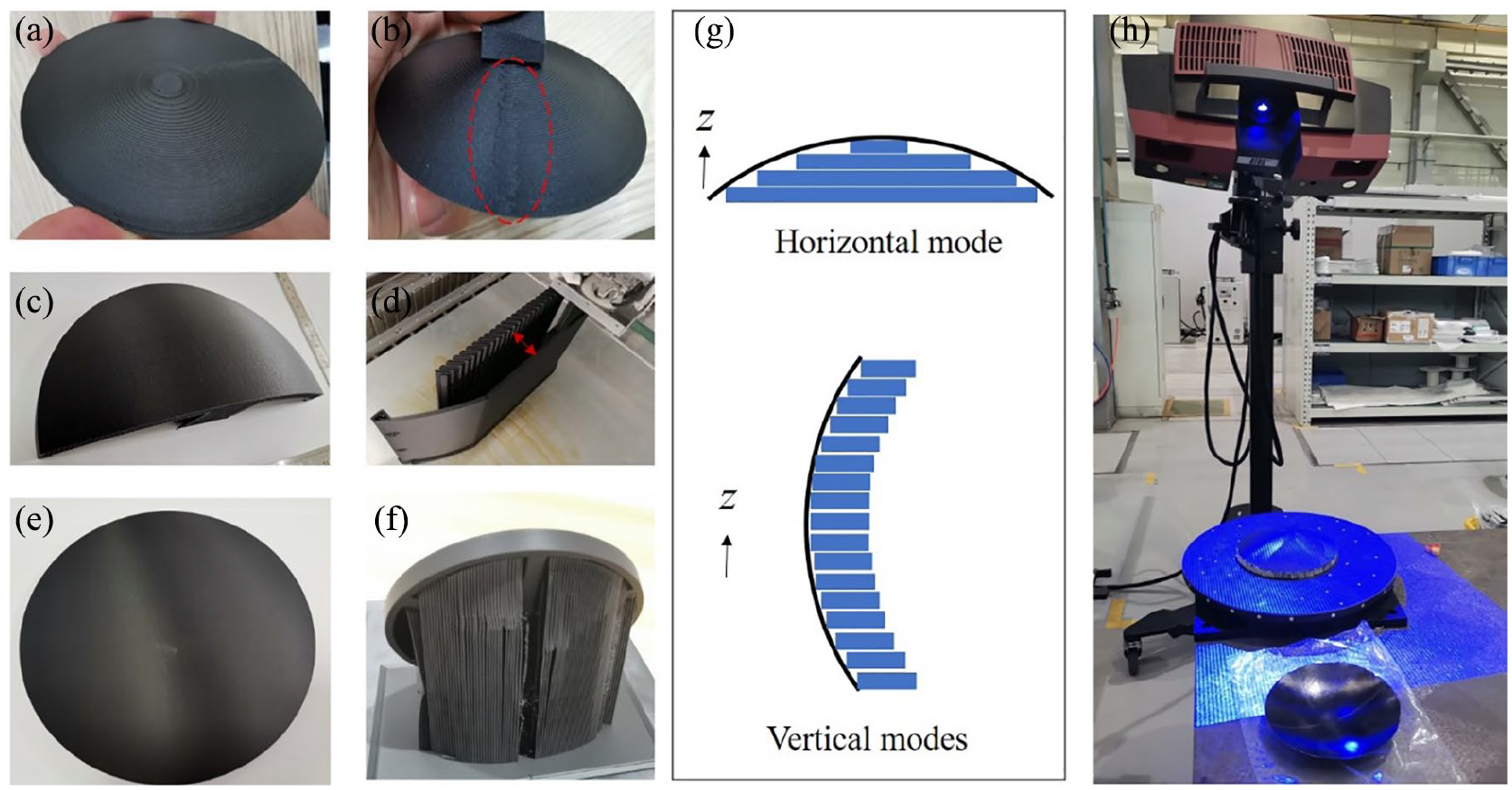
3D-printed molds by horizontal mode (a and b), vertical mode (c and d) and inclined mode (e and f), the schematics of paraboloid profiles consisted printing layers (g) and the photo of 3D profile measurement by structured light scanner (h).
To quantitatively characterize the printing precision of the antenna mode, structured light scanning was used to obtain the 3D profiles of the printed molds. Compared to the designed paraboloid profile, the average deviation of printed mold could be obtained. The average deviation of mold generated by horizontal mode is +0.21 mm/−0.11 mm and the maximum deviation is in the fusion mark area. The average deviations of the molds printed by vertical mode and inclined mode were +0.14 mm / −0.11 mm and +0.11 mm / −0.13 mm, respectively. The paraboloid mold printed by inclined mode exhibited best profile precision with lowest RMS deviation of 0.14 mm, while RMS deviation for molding demand was 0.2 mm. According to the average deviation and RMS data, inclined mode was the best way to 3D-print the parabolic antenna mold.
The parabolic antenna skin of carbon fiber composite was prepared by the method of vacuum bag on the 3D printed mold (I-mold). Eight layers of CF/epoxy prepreg with single layer thickness of 0.08 mm was laid with sequence of 0°/+ 45°/−45°/90° on the Teflon films covered Onyx mold. After vacuuming with vacuum bag, the CF/epoxy prepreg was cured at 135°C for 2 h. The fabricated CF/epoxy antenna was shown in Figure 4(a) and the I-mold after demolding has good surface quality. The average deviation and RMS deviation of the CF/epoxy antenna and I-mold after demolding were also measured by structural light scanner (seen in Figure 4(c)). From the data in Table 1, CF/epoxy antenna skin had average deviation and RMS deviation of +0.09 mm / −0.16 mm and 0.16 mm, respectively, which was very close to the I-mold. The profile precision of I-mold slightly decreased after antenna skin fabrication, however, it still fitted the demand of molding with RMS deviation of 0.2 mm.

(a) Photos during fabrication process of CF/epoxy antenna skin using the 3D-printed mold. (i) 3D-printed mold; (ii) sticking Teflon film; (iii) laying prepreg; (iv) laying vacuum bag; (v) CF/epoxy antenna skin. (b) Images of the mold 3D-printed by inclined mode after demolding of antenna skin. (c) 3D profiles of mold 3D-printed by inclined mode before (i) and after (ii) composite antenna skin fabrication and CF/epoxy antenna skin (iii).
Average deviation and RMS deviation of 3D-printed mold and fabricated CF/epoxy antenna skin.

Conclusion
In summary, we report a CF/epoxy composite antenna skin with high profile accuracy using a 3D-printed CF/nylon composite mold. It is shown the coefficient of thermal expansion (CTE) of 3D-printed CF/nylon composite in z-direction is 3 times higher than that in x or y direction. While isotropic CF/nylon composite is fabricated when using inclined 3D printing mode with 30°. Otherwise, inclined printing mode can also provide a smooth surface by decreasing the printing step patterns. After optimizing the printing setting, the parabolic antenna mold exhibited an excellent profile precision (RMS deviation of 0.14 mm) and CF/epoxy composite parabolic antenna was successfully fabricated. We believe that our research about 3D-printed isotropic and smooth thermal-plastic mold provides great support for low-cost and rapid manufactured parabolic antenna.
Footnotes
Declaration of conflicting interests
The author(s) declared no potential conflicts of interest with respect to the research, authorship, and/or publication of this article.
Funding
The author(s) disclosed receipt of the following financial support for the research, authorship, and/or publication of this article: This work was supported by the National Key Research and Development Program of China 2017YFB1103400.