
Abstract
In this article, we proposed a new approach to design the winding patterns of filament-wound composite pressure vessel with unequal polar openings with non-geodesics. To ensure the continuity of winding angles between trajectories along the cylinder and the dome, the non-geodesics for cylindrical part were used. The developed winding patterns of the vessels were simulated using the MATLAB software to verify the feasibility of the acquired trajectories. To demonstrate the performance in designing the winding path for big polar ratios, we analyzed vessels with polar pole ratios of 1:2–1:4, respectively. The developed winding patterns have successfully achieved uniform fiber distributions along the mandrel without severe overlap, except for the polar pole regions. To avoid the severe overlap between filament bands, we further studied the relationship among the winding pattern, bandwidth, and the number of tangent points, and derived a suitable bandwidth based on the winding pattern. These simulated results proved the effectiveness of the developed method in design of winding pattern with unequal polar openings.
Introduction
Filament winding is a technology for producing composite parts by winding reinforcing filaments on the mandrel surface of a desired shape.1–3 Products manufactured by filament winding technology have an excellent strength-to-weight and stiffness-to-weight ratio and can be used as high-pressure vessels in solid rocket motors, fuel tanks of fighters, liquefied natural gas tanks, torpedo launchers, and so on.4–8 In fabrication, the continuous fibers can be oriented to match the direction of major stress in composite vessels to improve the carrying capacity. However, these applications in the aerospace field are very sensitive to weight. To lower the launch costs, it is urgent to reduce the weight of each subsystem in the rocket. To produce the lightweight solid rocket, digital design of the winding pattern is the first step, and plays a key role in weight reduction. In a filament winding system, fiber tows under tension can be wound on the mandrel surface in designed patterns to form a uniform composite structure. 9 As a result, the winding pattern determines winding angle distribution, which has a considerable effect on the mechanical properties of composite vessels.10–12 Therefore, an optimized winding pattern can improve the carrying capacity, and simultaneously reduce the weight.11,13–15
The method of winding pattern design can be split into two ways: by using an analytical or a discrete method. For the analytical method, the winding patterns are calculated by differential equations.16,17 In the early stage, due to the conciseness, geodesics were widely used in the composite industry. 18 However, the geodesic winding parameters are unique when the mandrel geometry is determined, which restricts the design scope of winding patterns. To broaden the designability, the non-geodesics winding is more and more used in the filament winding on complex parts19,20,21 By employing the friction between the filament bundles and its supporting surface, the non-geodesics significantly enlarge the available winding path. Koussios22,23 derived the basic equation for non-geodesic filament winding on generic shells of revolution, which laid the foundation for winding patterns design. For filament winding of complex shape mandrels, a unified approach 24 was developed to simulate the filament winding process. However, this method is more suitable for convex and concave geometries. The spline method 25 for winding pattern design was proposed for non-axisymmetric winding in the composite industry. Zu et al.26,27 proposed the winding pattern design of pressure vessels, and further improved the dome section performance. The discrete method subdivided the whole revolved surface into a sequence of sections to calculate the fiber trajectories. An algorithm was proposed for non-axisymmetric structures comprising rectangular facets that compute the filament paths. 28 However, this method is limited to a polygonal cross-section mandrel. To overcome the defect, Fu et al. 29 used a triangular mesh termed as the stereolithography (STL) model to calculate winding paths for both axisymmetric and non-axisymmetric mandrels. Furthermore, Fu et al.9,30 developed some different methods for generation of winding path for abnormal mandrel based on STL model, including the method of winding path generation based on the inverse process of stability analysis and that based on the principal stress. In the principal stress field method, variable winding directions as close as possible to the major principal stress directions of the product are calculated to generate filament-winding paths that can endure the maximum load and satisfy the requirements of the winding manufacture. In the method of winding path generation based on the inverse process of stability analysis, according to the inverse process of stability analysis, the next path point satisfied the stability conditions. This method can be applied to both axisymmetric and non-axisymmetric mandrel models represented by triangular patches. However, these methods require a lot of calculation effort and are not suitable for fast winding pattern designs of filament–wound composite pressure vessel with two unequal polar poles in the early stages. 25
Overall, most of these methods focused on the subpart sections or the full part of the mandrel for winding pattern design and overlooked the transition zones of fiber trajectories between the dome and the cylinder. In essence, the transition zones played an important role in designing the winding pattern for a vessel, especially in the solid rocket motor case field with a big polar pole ratio. For example, the ideal winding angle of a helicoidally geodesic path over the cylindrical body is
The purpose of the present article is to develop a digital method to design the winding patterns of a filament–wound composite pressure vessel under the limitation of unequal polar openings and the requirement of continuity in winding. Furthermore, to obtain a suitable bandwidth in winding, we proposed a model to find the relationship among the winding patterns, bandwidth, and the number of tangent points. This article is arranged as follows: in section “Differential equations for winding angle and rotating angle of mandrel,” we reviewed differential equations of non-geodesics, which are the fundamentals of the winding pattern design. In section “Winding pattern design for composite pressure vessel,” we demonstrated the detailed method to design the winding pattern of a vessel with unequal polar poles. In section “Computer implementation of the designed winding pattern,” the detailed procedures of computer implementation of the designed winding pattern were given to verify the feasibility of the designed winding pattern. In sections “Results and discussion” and ”Conclusion,” some results and discussions were conducted.
Differential equations for winding angle and rotating angle of mandrel
Winding angle equation
For the winding pattern design, it is necessary to have a unified equation to describe both geodesic and non-geodesic winding. The following equation is effective 27
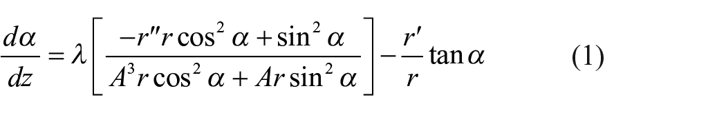
where

Geometrical relationship of filament trajectory on a revolution surface. (a) Fiber trajectory on a revolution surface. (b) Geometrical relationship between
The rotation angle of mandrel
Figure 1 shows the geometrical relationship of filament trajectory on a revolved surface. A-P-B is the fiber path, R cylindrical radius, and

where

By the geometrical relationship of

Using the trigonometric function relationship, the cosine value of angle
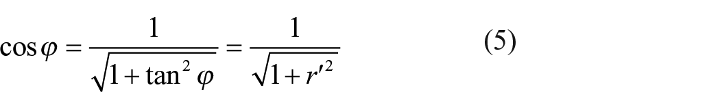
where

Simultaneous solution of the system of differential equations (1) and (6) will finally yield the winding angle and angular coordinate distribution along the axial direction, so the fiber trajectory on the revolution surface will be determined using the angular coordinate.
The filament winding process requires perfect tangent placement of the roving when passing the polar pole of the dome to make filament continuous to a next wound circuit. Therefore, the winding angle at the polar opening should equal 90°. It should be emphasized that a slightly reduced value for
Winding pattern design for composite pressure vessel
To design the winding pattern for a vessel, it is necessary to study the pathways for both the dome and cylindrical sections. This section will give the distribution of the fiber paths for different
Fiber pathways on dome section
Figure 2(a) shows the winding angle curves along the axial direction on the dome surface with different slippage coefficients

Winding angle and pathways distribution on ellipsoidal dome with various
Figure 2(b) plots the fiber trajectories distribution with different dome heights and slippage coefficients on an ellipsoidal dome. To compare the distribution of these pathways, the initial points that are located at the dome–cylinder conjunction of all these trajectories are set to the same point. For
Fiber pathways for cylinder section
For the cylinder section, considering the meridian equation is


where
Figure 3 shows the fiber trajectories on the cylindrical surface with various
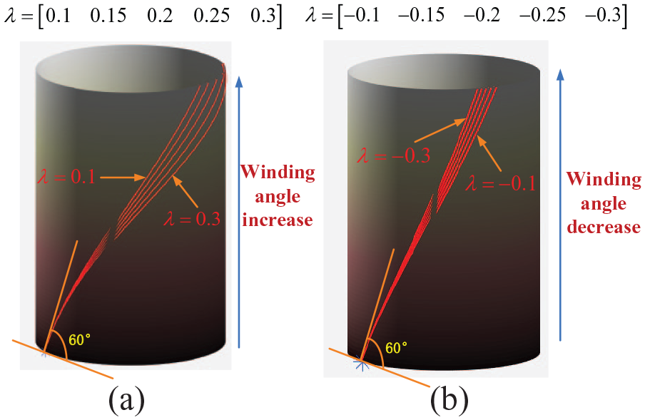
Fiber trajectories on cylindrical section with different slippage coefficients
Winding pattern design for a vessel with unequal polar openings
Figure 4(a) illustrates the winding pattern scheme for a vessel with unequal openings. The vessel is divided into three parts: left dome, cylinder, and right dome. Each part has two possibilities: geodesic and non-geodesic. Owing to this division, there are eight winding schemes for the vessel. Previously, the winding pattern design for a vessel usually adopted a constant winding angle for the cylindrical section. Nevertheless, this is not always feasible, especially when the radius of the polar pole is much bigger than another one. Consequently, it is necessary to employ variational winding angle for the cylinder section to design the winding pattern for a vessel with two unequal openings, and this scenario is more complicated.

Winding pattern schemes for a vessel with unequal openings. (a) Winding pattern scheme for a vessel. (b) Winding pattern scheme for its cylinder section.
There are five patterns for the cylindrical section, as shown in Figure 4(b). The five scenarios are (1) left non-geodesic, middle geodesic, and right non-geodesic; (2) left non-geodesic and middle geodesic; (3) left geodesic and right non-geodesic; (4) geodesic for entire cylinder section; and (5) non-geodesic for whole cylinder section.
To ensure fiber stability and full coverage on the mandrel, four conditions must be satisfied, as follows: (1) all tangent points of a circuit evenly divide the cross-section; (2) the circumferential distance between adjacent rovings at a proper situation is the bandwidth; (3) the winding angle is contiguous; and (4) the slippage coefficient
The dome end angle interval is defined as the winding angle interval at the dome–cylinder conjunction when the

Winding pattern design of both sides of dome end angle intervals having no intersection.
For convenience, let
1.
In this case,

while

where
2.
For this scenario,
3.
In this case,


If

4. α1 is in the fourth design section
Under these circumstances, the value range of
5.
Condition summary with dome end angle intervals having no intersection.

For the case when both sides of the dome end angle intervals have no intersection and

When both sides of dome end angle intervals have an intersection as shown in Figure 6, a similar process is carried out to design the winding pattern. Under this scenario, the third design section has a constant winding angle in its cylindrical section. But in any other design sections, it is unable to use the geodesic pattern in the cylindrical section to wind. To satisfy the non-slipping condition and winding angle continuum condition, it is necessary to adopt the proposed method of winding pattern design.

Winding pattern design of both sides of dome end angle intervals having intersection.
Computer implementation of the designed winding pattern
Before filament winding, simulations prove a tool to verify whether the predesigned path is appropriate at a low cost. Here, we show the simulated winding process using the computer. The proposed algorithm for the filament winding pattern simulation was implemented using the MATLAB software platform in a Windows 7 environment. To avoid producing a gap that leaves the mandrel exposed, the method of full coverage of filament band on mandrel needs to be developed.
Searching slippage coefficients
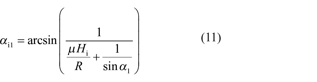
A key factor in this design is the determination of a pair of slippage coefficients for both the dome parts, to provide non-geodesic winding with unequal polar openings. The filament winding process requires perfect tangent placement of the rovings when passing the polar areas of the dome structure, to make it continuous to the next wound circuit. As a result, by application of the non-geodesic roving trajectories, the requirement must be met. The winding angle at the polar area should reach

To prevent slipping of the rovings on the supporting surface, the slippage coefficient

where µ is the friction coefficient between the fiber bundle and the supporting surface. Here the slippage coefficient is given by a piecewise function

The target is to find a pair of slippage coefficients
Flowchart of searching slippage coefficients.
The process of computer implementation
During the filament winding process, the fibers are wound on the mandrel surface in a continuous manner and are tangent to the opening at its polar radius. Therefore, the mandrel angular

where
Schematic diagram of computer implementation of designed winding pattern.
To visualize the designed winding patterns, the process of fiber paths implementation for a wound cycle is separated into six portions: cylindrical winding section, right dome up section, right dome down section, cylindrical back winding section, left dome up section, and left dome down section, as shown in Figure 8. After a cycle winding, the mandrel angular
Flowchart of computer implementation of designed winding pattern.
Full coverage
To ensure the mandrel is uniformly covered by fibers, the number of wound circuits (a wound circuit is defined as the winding process in which continuous fibers start at a certain point on the mandrel surface and wind several cycles before returning to the starting point.) must be acquired. In a filament winding system, fiber tows under tension are wound onto the mandrel surface side by side in designed patterns to form a uniform composite shell that is precisely manipulated by computer numerical control. Consequently, the circumferential distance between each circuit path at the proper situation should be a bandwidth to avoid producing a gap that leaves the mandrel exposed. The distance is defined by a pitch angle
where b is the width of the filament band, D is the diameter of the mandrel at the location on the z-axis, and

where n is the number of tangents; and Ci and Cy are the number of circuits and cycles when the mandrel is uniformly covered by filaments. Ci is a real number but Cy is an integer number. The circumferential width of the individual filament band placed on the mandrel is not necessarily an integer multiple of the cross-sectional circumference of the mandrel. As a result, the overlap of filament bands may exist in the last wound circuit, as shown in Figure 10. It demonstrates the process of a mandrel uniformly covered by fibers, which includes the first circuit, the sixth circuit, and the final circuit winding, and the results show that the mandrel can be coated uniformly with filament bands, which indicates the effectiveness of the proposed method.
Non-geodesic winding pattern simulation for the first, sixth, and final wound circuits with the number of tangents at 3.
In order to quantify the cover factor and overlap of filament band, Cf and Lap are defined as cover factor and overlap factor of filament band. Cf represents the cover degree of filament band after a layer of finished winding. Combining equation (21), cover factor Cf is expressed as

Combining equation (22), the overlap factor of filament band is obtained as

The relationship among the number of tangent points, roving bandwidth, and winding pattern
Once the mandrel geometry and winding parameters of composite vessel are determined, the winding pattern is simultaneously given and the critical roving width is a desirable parameter for manufacturing the vessel. When the real bandwidth is less than the critical roving width, a gap will appear between two adjacent rovings in some area of the vessel. By contrast, while the real bandwidth is greater than the critical roving width, the overlap of rovings exists between adjacent yarns in all areas of the wound product. Here, let
For a mandrel, the angle of the mandrel for a pay-out eye cycle is a constant while the winding pattern is determined. The critical bandwidth is related to the angle

Schematic diagram for the number of tangents: (a) 4 tangents. (b) 23 tangents.

Flowchart of the calculation method of critical bandwidth and the number of tangents.
Results and discussion
The simulation system has the ability of designing the winding pattern for a vessel with unequal polar openings. The simulation system has the ability of rotation, panning, zooming, and view switching, which enable the designer to observe the winding process by dragging the mouse. If there are any abnormal phenomena during the filament winding process, the engineer can stop and adjust the winding pattern until the filament bands cover the mandrel uniformly. Therefore, the simulation is convenient and effective in producing a composite vessel.
To validate the ability of generating winding patterns of the developed simulation system for vessels with different ratio of polar poles, Figure 13 displays non-geodesic winding patterns for revolution shells with different ratios of polar openings for
Non-geodesic winding patterns for revolution shells with different ratios of polar openings.
For the sake of displaying winding patterns for different design sections for a certain vessel, a revolution shell is selected and the geometrical parameters are depicted in Figure 14. The semi-minor axis and the semi-major axis are 330 and 385 mm, respectively, fiber bandwidth

Dimensional parameters of a revolution shell.
Figure 15 gives the winding angle curves along the axial direction for four design sections of winding pattern of the vessel. When

Winding angle curves with respect to z axis for
Table 2 shows that numerous tangent points and bandwidths for each design section of winding pattern could be selected. For the first and second design sections, as the tiny angle
The number of tangent point and bandwidth for different design sections of winding pattern.

Conclusion
In this article, the method of winding pattern design of filament wound composite pressure vessel with unequal openings was proposed using geodesics and non-geodesics, which also satisfy the winding principles. A model was established to determine the relationship among the number of tangent points, bandwidth, and winding pattern, which aim to ensure the fiber stability and full coverage on the mandrel to satisfy the winding process requirements. The winding patterns for composite pressure vessel were simulated on the MATLAB software platform to verify the feasibility of the trajectory deign. The simulation results indicate that the mandrel was coated with fibers uniformly and no severe overlap regions except the polar pole regions exist on the mandrel surface, which proved the effectiveness of the method. The method introduced in this article can be used in the early stages of designing a composite pressure vessel, especially in a solid fuel rocket case.
Footnotes
Appendix 1
Declaration of conflicting interests
The author(s) declared no potential conflicts of interest with respect to the research, authorship, and/or publication of this article.
Funding
The author(s) disclosed receipt of the following financial support for the research, authorship, and/or publication of this article: This research is supported by the Joint Fund of Advanced Aerospace Manufacturing Technology Research (Project No. U1837601).