
Abstract
Jacquard weft-knitted fabric is a type of multilayer knitting fabric which has a stereoscopic surface with complex patterns. A computer simulation system was established, based on a virtual fabric Unity3D platform, to minimize the time required for computer simulation and to enhance the simulation results. The three-dimensional fabric data were unified and coordinate data were obtained to achieve the establishment. Three factors of simulation algorithm for jacquard weft-knitted fabric were used to establish and control the effect of a fabric model. By integrating three-dimensional model data, two-dimensional spatial data, and gray model, virtual simulation based on three-dimensional engine Unity3D platform was realized. Based on the real-fabric data, the final fabric patterns were predicted from macroscopic angle instead of two-dimensional and microscopic simulations. The system is proved to be more effective for the prediction and simulation of jacquard weft-knitted fabric and other fabrics having similar stereoscopic surfaces.
Introduction
The usage of three-dimensional (3D)-effect fabrics has gained popularity in the textile and apparel industries in the last decade. Jacquard weft-knitted fabrics (JWKFs) are commonly employed in fashion design and household textiles because of their high productivity, low fabrication costs and pollution, soft handling, high adaptability, and 3D jacquard effect, as shown in Figure 1. Different types of fibers, including spandex, draw texture yarn, staple rayon, and bamboo charcoal fiber, have been used to create these heterogeneous fabrics for different applications. Also, different patterns in double-faced structures can be employed to enrich fabric product variety. Fiber diameter, assembly forms, and material characteristics play an important role in influencing the texture of fabrics. Inlay yarn in a fabric could also play a dominant role in defining some of the fabric properties, especially the fabric gram weight. 1 Over the last few decades, predictive models have been developed to find effective properties of knitted fabrics based on their loop forms and yarn properties. Predictive models to find effective properties of weft-knitted fabrics range from the constituent material properties such as contents of inlay yarn, colors of the jacquard yarn, and thickness of fabrics in the system. Effective properties have also been determined using numerical methods which can address the specifics of fabric pattern geometry. 2 The effective properties determined from an analytical constitutive relationship can be readily used in pattern design, production, or computer-aided design (CAD) and hence are very desirable.

Real sample of JWKF.
Several researchers have formed different methods to determine geometrical loop models, such as B-spline method and Pierce loop, in modeling woven and knitted fabrics.3–5 These studies have helped to improve and develop computer-based design systems. The resulted loop models can also help designers to improve the accuracy of simulating the fabric appearance where fabric structure needs to be visualized. 6 However, problems still exist in some 3D fabrics. In simulating a fabric through microsimulation, connecting all loop models of the fabric would be time consuming. Cross section of a real fabric has been applied to objectively evaluate the surface ruggedness of fabric wrinkles and seam puckers. 7 Image processing of fabric sectional pictures with different methods is useful for fabric defect detection.
Earlier, fabric computer simulations started from geometric approach. Because physical factors and elastic coefficient of quality fabric were not taken into account, simulation results and applications were not satisfactory. Based on the physical model method, fabric model is mainly divided into four categories: elasticity-based model,8–10 mass–spring model,11–14 particle model,15–19 and finite element model.20,21
In mass–spring model, fabric is looked upon as distributed connected grid. Masses are interconnected by different types of springs. The force of each mass is obtained by a certain particle velocity and acceleration integration method is used to simulate the effect of the fabric. The more the number of mass, the more the real simulation results, and the amount of calculation will also rise unexpectedly. Finite element model is part of the continuous media type model. It is more realistic and useful to simulate the effect of objects. The object is divided into interconnected elements, with each element in turn computing power, speed, and acceleration, according to the time integration. However, it is not an appropriate method in terms of real-time simulation process which is too complicated and time-consuming. Because the fabric itself exhibits the characteristic of knitted mesh, in this research we have chosen reference particle model system to establish a low detailed model. For static computer simulation of the fabric surface, interacting direction particles are with the direction attribute, in addition to dynamic properties such as speed and position, which is conducive to rapid implementation of uneven fabric simulation effects.
Currently, some commercial enterprises have made remarkable achievements in the 3D simulation of flat-knitted fabrics like YXENDIS (France), Kniterate (UK), M1-STORE (Japan), and SDS-ONE Knit Paint- SHIMA SEIKI (Japan). On one hand, the simulation based on the loop model is time-consuming on the weft-knitted fabric because of the huge number of loops. On the other hand, 3D weft-knitted fabrics does not need to pursue simulation of each loop, but focuses on the reflection of concave and convex effect. In this work, we will focus on thickness prediction of JWKF from a 2D perspective. Our approach is to predict the final fabric 3D motif before production using very detailed mesh models of a unit that represents the geometry. A “three-factor algorithm” will be used to describe 3D fabrics. The results are compared with existing analytical models. The results of a parametric study are evaluated to provide a design guideline in terms of content of inlay yarn and knitting parameters for material selection and design.
Research principles and approaches
Fabric design and production
JWKF is produced by a computerized jacquard circular knitting machine. Quilting double-faced structure is a basic structure for this fabric. Stereoscopic effect is an obvious characteristic that differs from other knitted fabrics. Reverse loop stitch is knitted on both right side and left side controlled through an electronic needle selection device. The surface density and the content of inlay yarn which is fastened between the two faces determined the degree of stereoscopic effect of fabrics. 1 There is a difference between original pattern designed and final fabric motif knitted, as shown in Figure 2. The main difference is on the fringe of patterns. The higher the surface density, the more obvious the surface irregularities of the fabric. To enable a virtual reality of stereoscopic effect for fabric patterns, we focus on the unit surface effect from macroscopic perspective instead of the model of single loop. Forecasting different surface densities of the fabric from 3D angles reduces product time and helps to improve development capability through the knitted fabric design by CAD.

Images of JWKF: (a) pattern design image and (b) real fabric image.
To establish the simulation system, the data acquisition and measurement of the jacquard fabric is the first step. Unit influence range, depth, and number of iterations were proposed. The three-factor simulation algorithm is generated which contained high levels of gray image, and normal mapping technology is used to enhance its 3D effect. Combined with texture mapping technology based on the Unity3D platform, a specific process is used to achieve a real virtual display (Figure 3).

The flow chart of system establishment.
The 3D weft-knitted jacquard fabric pattern comprises a basic pattern and a main pattern. The stereoscopic effect changed with fabric pattern changes. The basic pattern fastened the inlay yarn and the right and left side of fabrics, enhancing the sense of the main pattern. The fabric section was regular and clear, as shown in Figure 4(a). According to the demand of the design, the main pattern produced the aesthetical appearance of the fabric by increasing the number of colors and fabric 3D effect. The fabric section was irregular on the basis of the pattern as shown in Figure 4(b).

The threshold image of the sample: (a) the cross section diagram of regular pattern of jacquard fabric and (b) the cross section diagram of irregular pattern of jacquard fabric.
In the experiment, 1#–4# samples are knitted by an OVJA 1.6EE Mayer&Cie computerized jacquard circular machine. The main measurement parameters are surface density and thickness of the fabrics. Affected range of the unit jacquard loop is calculated by image processing (Table 1). Figure 5 shows the affected range. To make the experimental results more accurate, a kind of basic pattern is chosen to be an experimental object. The influence range of unit jacquard loops is propitious to measurement and observation. The samples are knitted with the same process and raw materials except the content of inlay yarn. As shown in Figure 6, black spots are due to jacquard loops, the distance between any two loops is 1.5 cm, which could ensure no effect on the interaction of two adjacent loops.
Weight, diagram, and threshold diagram of samples.


The influence diagram of each jacquard loop.

The diagram of jacquard fabric.
Measurement and calculation
By turning the fabric section microscope image into the threshold image, the outline of patterns is distinct. According to the relationship between the thickness difference of the fabric surface and the number of the image pixels, the length of the surface projection is calculated by

where l is the surface variation range, h is the thickness of the sample, h1 is number of pixels for fabric thickness, and l1 is pixel number of variation range.
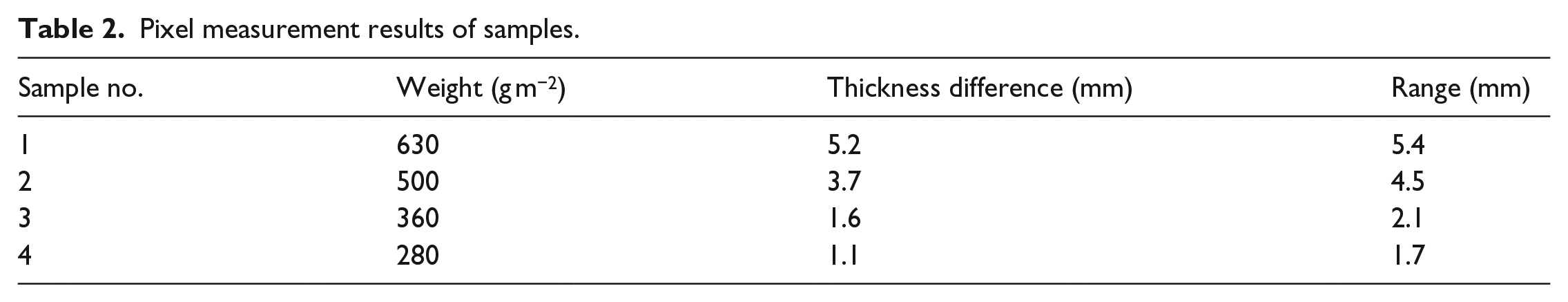
After measuring the thickness difference and the projection length, according to the obtained data (Table 2), the cross section curve equation of the fabric caused by the jacquard yarn is obtained. Assuming a fabric with a regular surface profile, a Cartesian coordinate system can be erected with one X-axis along the direction of its width, and another Y-axis along the direction of its length, as illustrated in Figure 7. 7 With the assumption that relying on the profile curve has significant effects on the final rugged fabric, a contour generator based on the regular deformation of the surface profile can be designed to explain the process clearly. Figure 6 illustrates that a rotating fabric surface starting from one end to the other end along the Z direction can generate a model. The diagram can record its surface profile of each compression through the curve. The origin of the coordinate system o is the thinnest point of the sample. The thickness of the sample is mn. The distance of every compression caused by a connected loop is om. The line on is a curve that describes the situation of the compression. Based on the curve, we can analyze the change of fabric thickness accurately.
Pixel measurement results of samples.
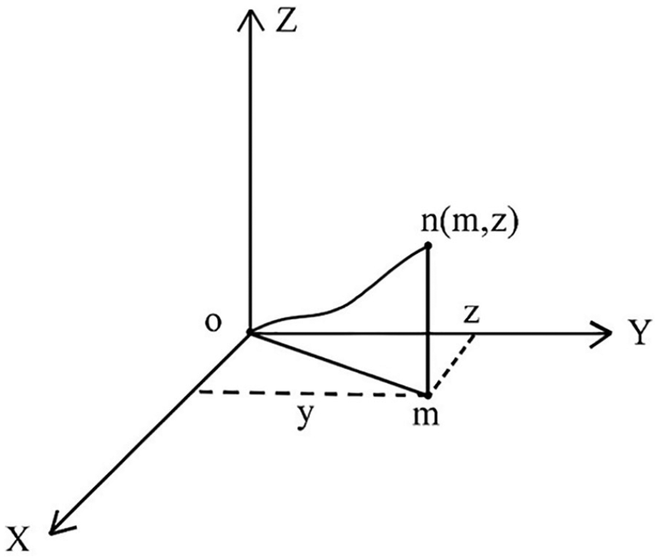
A 3D schematic diagram of fabric’s sag area.
Three-factor algorithm of fabric simulation
The key factors affecting the concave convex effect of the fabric were obtained by the fabric test and 3D model of the unit jacquard loop. These factors are controlled by the thickness of the fabric, the projection range, and accurate curve equation. But, the complexity of varied jacquard fabrics hinders the result of simulation process. Irregular or continuous pattern also disturbed model establishment and delayed the simulation time. Therefore, according to the characteristics of irregular stereoscopic effect and wide variation range of complex jacquard fabrics, we proposed a simulation algorithm for the 3D fabrics based on a cross section curve equation.
First, all jacquard loops are defined as center of mass points corresponding to the grid mesh according to the coordinate position. The particles are uniformly distributed on the space grid, and moved downward imitating the internal force. Then, the particle is forced to drop to the center to simulate the condition of the jacquard loop fastening three layers of the fabric. The mesh is formed in a conical depression because the surrounding particles are not affected, as shown in Figure 8.
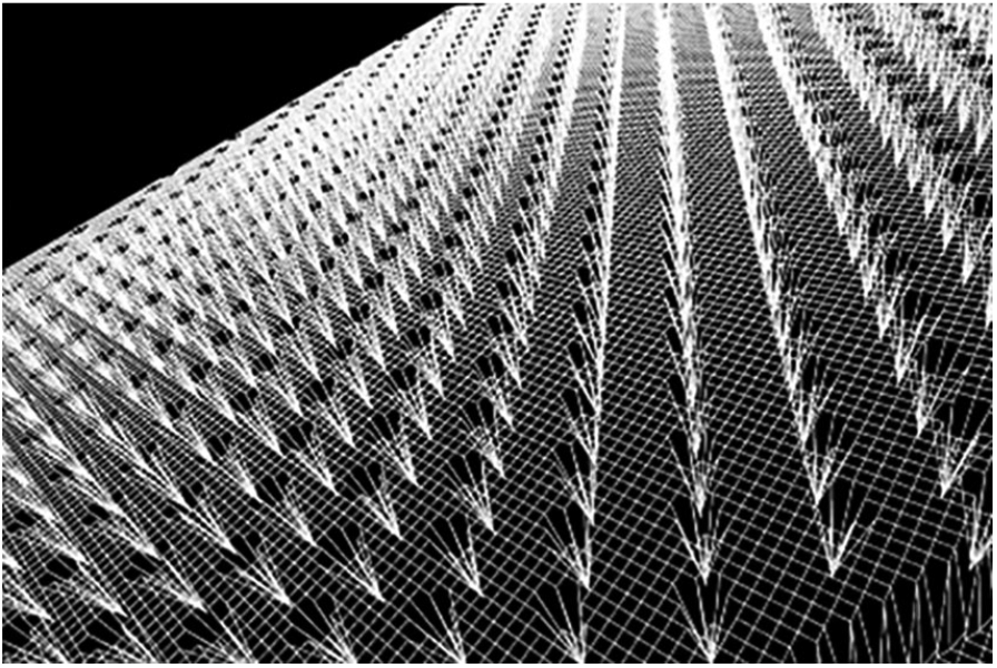
Simulation diagram of the pattern grid.
In the particle system, the structural spring has constrained the changes of two adjacent particles. In this study, we set up a pair of link to join any two adjacent particles. The value is approximated through limiting the distance between the two particles. In case if the pit of the particle would not cause surface mesh mutation, the numerical value will be adjusted to the corrected value. Every time to adjust means an iteration (D) which could improve the position of particles.
It is possible to adjust the related data in each group referring to Hooke’s law

where F is the adjusting range, K is the influence coefficient, X0Xj − X0Xj is the change in the distance between X0 and Xj,
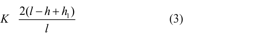
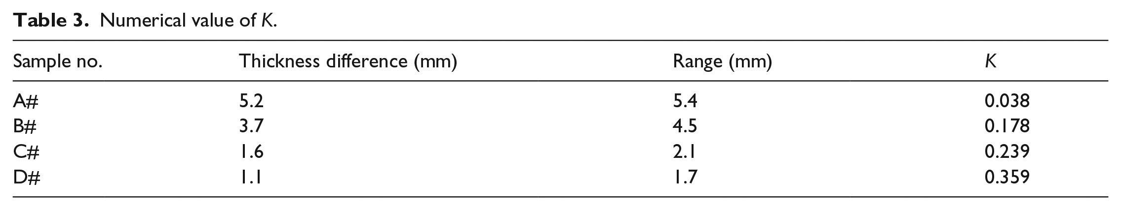
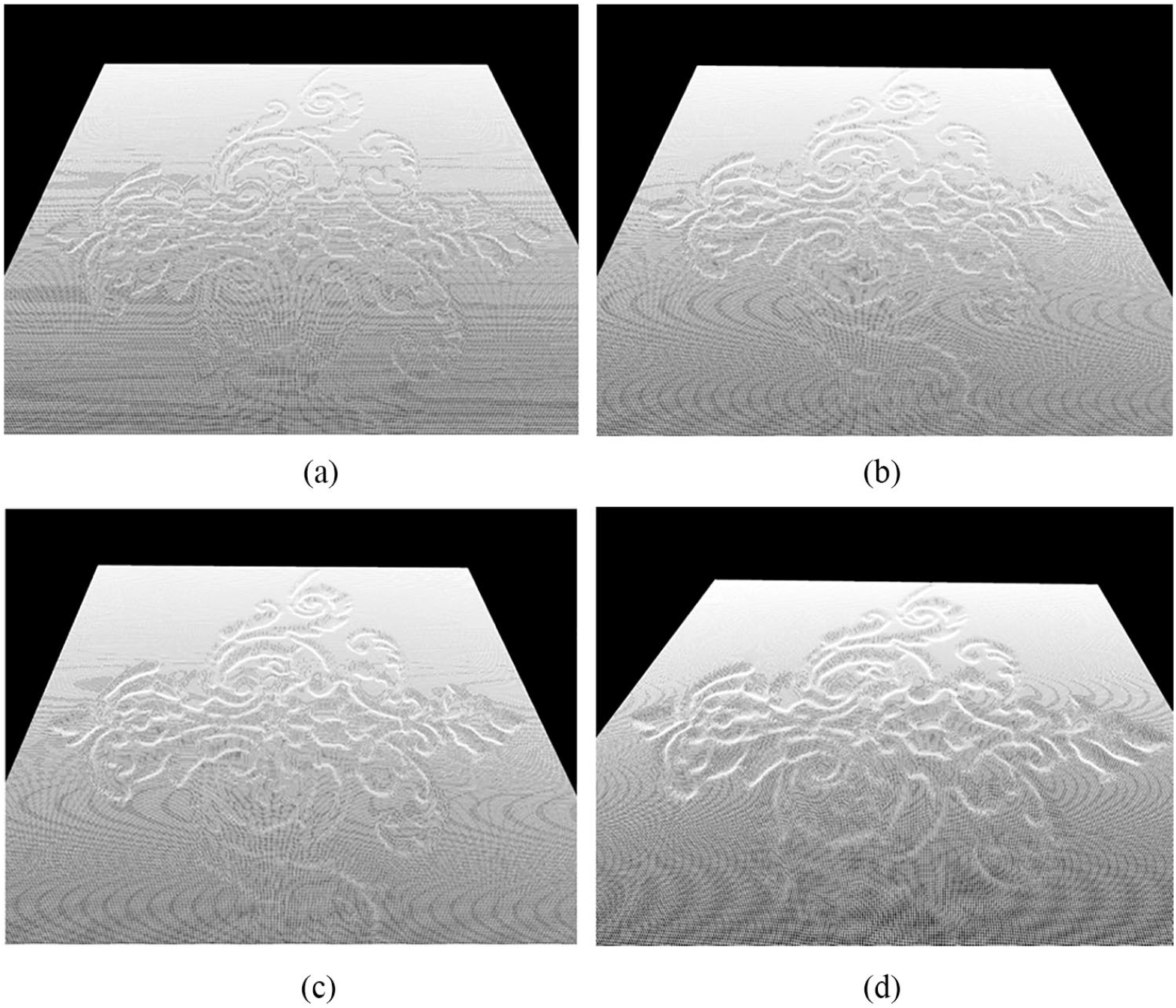
where h − h1 is the fabric thickness difference and l is the distance of projected range. The influence coefficient is determined by equation (3) and the data of real fabrics are shown in Table 2. The simulated results are listed in Table 3. In case where the fall in depth and the frequency of iterations are same, then, larger the influence range smaller the influence coefficient. The stereoscopic effect is simulated with different K values, as shown in Figure 9.
Numerical value of K.

Simulated fabric diagram with different influence factors (A#, B#, C#, and D#).
To sum up, this article presents a simulation algorithm for complex jacquard fabric, which includes three factors: depth (D), iteration (I), and influence (K). By determining and adjusting the three factors, the curve of the model is fitted with the real data of the fabric. The simulated results indicated that the fine particle system could be used to show the details of the fabric. Due to the real-time rendering of the requirements, the degree of subdivision of the research is not treated as a parameter adjustment.
Normal mapping technology
Normal maps obtained by mathematical methods of bump mapping and the tangent space were used to achieve the height of gray image that is able to reflect the uneven surface of the fabric. 22 , 23 This technique is suitable for terrain slopes gently, and concave convex mapping operations are performed at each vertex position to calculate the direction vector L. (Tangent vector T′ is read from the attribute array of vertices, and the B′ vector is computed from the matrix of the object space to tangent space.) Combined with RGB encoding format, the concave convex mapping coordinates and texture mapping coordinates were recorded. As shown in Figure 10, the two different vectors (1, 0, Hr, Hg) and (0, 1, Ha, Hg), where Hg is the current pixel, Ha is the above pixel, Hr is the pixel on the right, are calculated using data from a height map, while the normal map is equal to their outer product. The use of normal map and texture mapping technologies was propitious to enhance the real sense of the fabric. The formula is as follows


Sketch map of pixel position.
System implementation and verification
System framework
We developed a method to simulate uneven jacquard-knitted fabrics and established a 3D simulation system based on the Unity3D platform for weft-knitted jacquard fabrics. As a multi-platform game development tool, Unity3D platform can create 3D video games, real-time 3D animation, architectural visualization, and other types of interactive contents of the multi-platform integrated development tools. It is currently the most promising professional game design engine. 24 The interactive simulation process can be completed quickly and efficiently with the requirements of the virtual display.
Input of the pattern file is the first step to run the system, and the coordinate data of depression are analyzed and determined. The target thickness of the fabric played a very important role in the selection of three main factors. After the recognition of the position of the pixel coordinates, the program enters the iterative procedure. It is the key of the simulation process to generate the gray level image with height information. Finally, distinguishing the image is in line with the expected requirements. Repeat above steps if the simulation result is not satisfied. The simulation process flowchart, deployment diagram file system implementation, and system display organizational chart are shown in Figure 11(a)–(c).

Construction flow chart of simulation system: (a) system simulation flow chart, (b) deployment diagram file system implementation, and (c) system display organizational chart.
System module settings are shown in Figure 12. In addition to the capability of predicting the 3D jacquard-knitted fabric effect, the simulation system has the following three features:
Scene real-time display, real-time control, and display the fabric model and light effect.
Dynamic loading scene, according to customer needs to add and delete virtual scene, such as bedroom, living room, and so on.
Virtual interactive operation to achieve the zoom, translation, rotation, and other dynamic real-time tracking and positioning using the mouse, touching the screen, and other ways.
Setup dynamic tracking function, virtual display effect using the automatic positioning of cursor, enhancing the user’s roaming experience.

Schematic diagram of system module.
Simulation result of the system
Verification of the simulation was implemented using the developed method. Generated results are described below. Design of a decorative pattern jacquard fabric is shown in Figure 13. Using four groups of cross section equation to establish fabric models. Simulation results are shown in Figure 14. The test result indicated that simulation maps clearly show the jacquard part caused by the fabric 3D effect. Different cross section equations can reflect different stereo effects according to actual fabric. Moreover, Figure 15(a) is complex pattern design and Figure 15(b) is a top view of the simulation effect. According to the technological rules, the image produces a reasonable stereoscopic effect. After rotating and enlarging the simulated image, the loop depression area (Figure 15(c)) can be obtained. The concave and convex effect of the actual fabric surface can be simulated quickly. According to the experiment, the system can predict the final effect of jacquard fabric with different surface densities before production.

Pattern image of JWKF.
A 3D simulation diagram of jacquard-quilted fabric with different weights: (a) 240 g m−2, (b) 320 g m−2, (c) 400 g m−2, and (d) 520 g m−2.
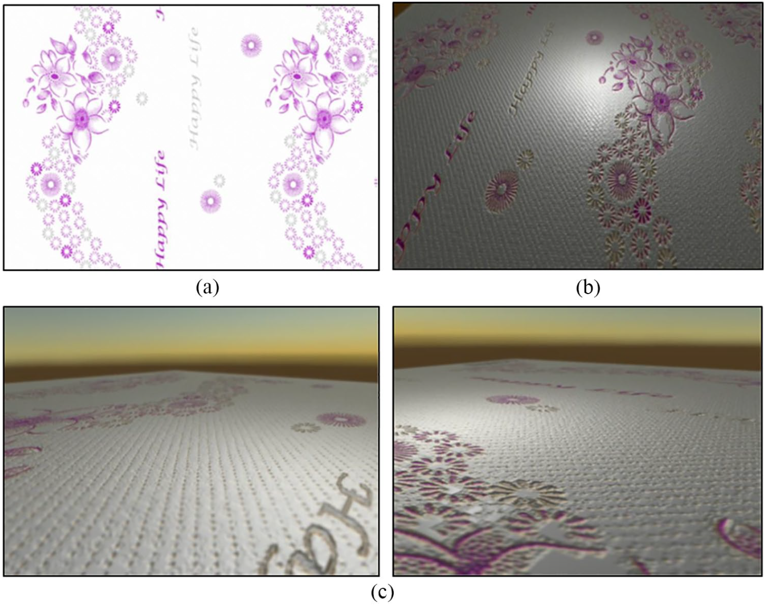
Comparison between pattern design and simulated figure of complex jacquard fabric: (a) design image, (b) planform view, and (c) side view (enlarged view).
Conclusion
In this article, a new simulation algorithm for complex 3D jacquard fabrics was proposed, through fixing and adjusting the three parameters such as sinking depth, the number of iterations, and the influence, for the scope to provide theoretical support to simulate the real fabric. The 3D model takes into consideration a comprehensive understanding of fabric geometric characteristics and describes the result by the final gray model with height information. The Unity3D engine and JavaScript C# were used to realize the 3D modeling, normal mapping, texture mapping, and other technologies to integrate simulation. Consequently, it is possible to simulate the surface of large-scale pattern, multilayer JWKF according to original design bitmap imported into the system. The developed simulation system can be used by knitting manufacturers in new product design and production.
Footnotes
Declaration of conflicting interests
The author(s) declared no potential conflicts of interest with respect to the research, authorship, and/or publication of this article.
Funding
The author(s) received no financial support for the research, authorship, and/or publication of this article.