
Abstract
In order to improve the defect of incompleteness, three-dimensional I-shaped fabrics with basalt fiber filaments tows were woven on the semi-automatic loom by reasonable design. Three-dimensional I-shaped woven composites were prepared by the vacuum-assisted resin transfer molding process. The compressive behaviors of three-dimensional I-shaped woven composites with three different heights and thicknesses were studied. Through the evaluation of load–displacement curves and total energy absorption of the three-dimensional I-shaped woven composites, the results indicated when the thickness was fixed to 2 mm, the maximum compression load with height 20 mm raised 522.72 N as against that with height 60 mm and the maximum compression load with thickness 6 mm raised 2571.81 N as against that with thickness 2 mm. Consequently, the compression properties of three-dimensional I-shaped woven composites decreased with the increasing heights of the composites, while increased with the increasing thickness of the composites. Analyzing morphological characteristics of composites after fracture and load–displacement curves of composites, it was concluded that the compression failure modes had brittle fracture of the fiber bundle, cracking of the matrix, and a typical shear failure in the beam (A2). Despite the above-mentioned failure mechanisms, the three-dimensional I-shaped woven composite still had good integrity without delamination.
Introduction
I-shaped preform is a common structure used in engineering application. The mechanical behaviors of the I-shaped composites have been investigated extensively.1–3 Most ordinary I-shaped composites were pressed with plate material, and the processing method was simple, but for the poor integrity of ordinary I-shaped composites which were easy to crack.4,5
Compared with ordinary I-shaped composites, three-dimensional (3D) I-shaped composites have many advantages, such as lighter weight and lower cost. 6 Therefore, more experts and scholars began to focus on the study of the properties of composites. Zhou et al. 7 studied the impact of mechanical properties of 3D braided composites by setting three kinds of gas pressure. The results show that the load, displacement, and energy absorption increased with the increase in the shock gas pressure. Zheng et al. 8 studied that the change in braiding parameters had a great influence on the properties of braided I-shaped composites. However, the 3D braided fabrics had lower transverse properties and they also had size and thickness limitations. 9 So, it was necessary to study the properties of woven composites. Nayak et al. 10 studied the E-glass/Epoxy two-dimensional (2D) plain woven composites, and 3D orthogonal woven composites were fabricated using vacuum-assisted resin infusion molding (VARIM) in different fiber weight fractions, and the mechanical properties of the two composites were compared. The results show that improvement in mechanical properties was seen with increase in fiber content in both the composites. Wicaksono and Chai 11 prepared 3D I-shaped woven composites and tested the composites by four-point bending experiment. The experimental results show that cracks appeared in the I-shaped composites, which may be caused by compression failure in the beam length direction. Even though a lot of researches had been done on the I-shaped composites, the compression properties of 3D I-shaped woven composites have not been discussed comprehensively so far. Therefore, it was investigated with the compression properties of 3D I-shaped woven composites with three different heights and three different thicknesses in this article. At the same time in the research of mechanical properties, the 3D woven composites with other shaped 3D woven fabric researched by Lv and colleagues12–15 also provided the basis for the 3D I-shaped woven compression property of this article.
In this article, 3D I-shaped fabrics with different heights and thicknesses were woven on the semi-automatic loom by reasonable design. In addition, the 3D I-shaped woven composites were fabricated by VARTM process, and then, the compression property tests were conducted on the microcomputer-controlled electronic universal testing machine. Finally, the load–displacement curves, total energy absorption, and the failure modes were obtained by experimental results.
Experimental
Materials and equipments
The matrix was epoxy vinyl resin (V-118), which was produced by Wuxi Qianguang Chemical Co., Ltd, China. 800tex basalt fiber filaments for warp and weft yarn were produced by Zhejiang Shijin Basalt Fiber Co., Ltd., China. The basalt fiber filament tows purchased from the company were directly used to weave without pretreatment. The low twist, 100 twists per 10 cm, had a good clustering effect on basalt filament tows. It was beneficial to the weaving of yarns and did not make the filaments entangle. The spinnability of this fiber was good except that the fiber was fragile in the vertical direction when weaving on the loom. Semi-automatic loom (SGA 598 from Jiangyin Tong Yuan spinning machine Co., Ltd., China) was used for weaving. VARTM molding system was used for molding, universal system prototype (QG-5A) from Kaya Industrial Co., Ltd, (Shanghai, China) was used for cutting samples, and universal testing machine (TH-8102S from Suzhou Tuobo Machinery Equipment Co., Ltd, China) was used for testing.
Design and weaving of 3D I-shaped woven fabrics
In order to prepare the 3D I-shaped woven fabric whose heights were not limited by the frame numbers of loom, the designing and weaving of the multi-plate weaving methods were adopted. They were all constructed by multi-layer connection structure, respectively. Because not only was the multi-layer connection structure compact and stable, but also the good shear resistance was shown. The sketch map of 3D I-shaped woven fabric was shown in Figure 1. A1 and A3 had not only the same shape and structure but also the same weaving structure. Therefore, the same warp structural drawings and chain drafts utilized in this article were also used to weave the structure of A1 and A3. This article used another different warp structural drawing and chain drafts to create the structure of A2 because of its difference from A1 and A3 in shape and structure. Meanwhile, the size of A1 was equal to A3 and the size of A2 was designed according to requirements. In order to weave different height fabric, different number of weft yarns was used to control the height when the beam was fabricated. And the force used to control the beating-up was uniform. Different number of warp yarns was used to control the thickness when the beam was fabricated. Besides, the height and the thickness were simply measured by the ruler. And in order to make the yarn shedding mechanism clear during weaving, the basalt tow was evenly divided into several parts and tied to the warp axis for uniform tension. In this article, the lengths of A2 were set to 20, 40, and 60 mm, respectively.
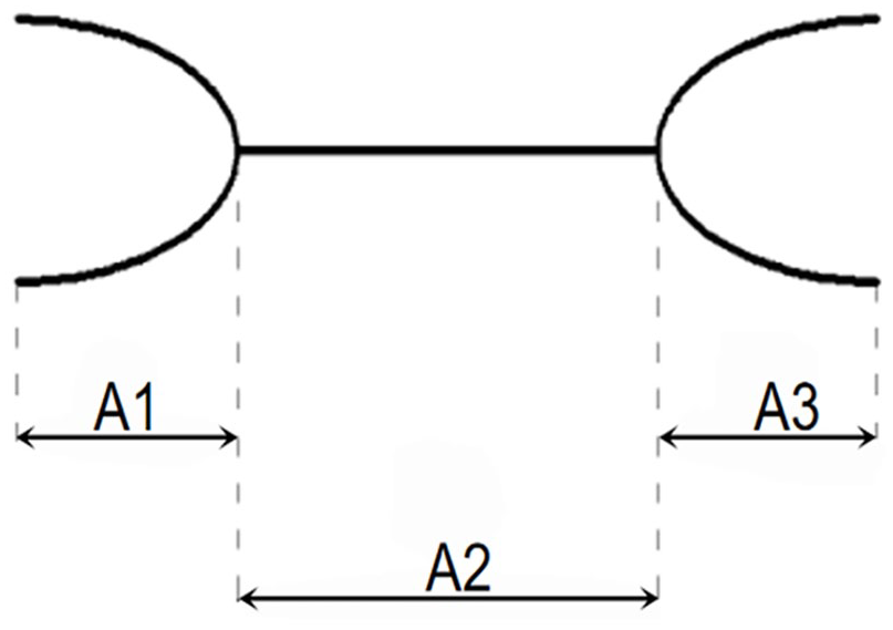
Sketch map of 3D I-shaped woven fabric.
The 3D I-shaped woven fabrics belong to multi-layer connection structure. The warp structure of 3D I-shaped woven fabrics was shown in Figure 2. In Figure 2, the warp structural drawings of A1 and A3 (Figure 2(b)) and the warp structural drawing of A2 (Figure 2(a)) were shown. The chain drafts of 3D I-shaped woven fabrics with three different heights were drawn according to the warp structural drawings which were shown in Figure 3. And the chain draft of A1 or A3 was shown in Figure 3(a) and the chain draft of A2 was shown in Figure 3(b).

Warp structural drawings of 3D I-shaped woven fabric: (a) The warp structural drawing of A2 and (b) The warp structural drawings of A1 and A3.

Chain drafts of 3D I-shaped woven fabric: (a) The chain draft of A1 or A3 and (b) The chain draft of A2.
The weaving parameters of 3D I-shaped woven fabrics were shown in Table 1. The 3D I-shaped woven fabrics were woven on the semi-automatic loom (SGA 598). 800 tex basalt fiber filament tows were employed as warp yarns and weft yarns. Finally, the 3D I-shaped woven fabric was shown in Figure 4.
Weaving parameters of 3D I-shaped woven fabrics.


The 3D I-shaped woven fabric.
Fabrication of 3D I-shaped woven composites
Epoxy vinyl resin (V-118) was used as matrix. Methyl ethyl ketone peroxide was used as solidification reagent, and cobalt naphthenate was used as a promoter. The 3D I-shaped woven composites were manufactured by VARTM. The schematic diagram of VARTM process was shown in Figure 5. In the VARTM process, blocks of wood were used as mold to support the fabric. The mold with flat surface and the same height as the beam was selected as the support. At the same time, the upper surface of the mold was tightened to the surface of the fabric to ensure that the upper surface was flat. Make the mold clamp the beam to ensure that the beam was vertical. Also, the role of its principle and structure of each part could be seen in literature.16–18

Schematic diagram of VARTM process.
The ratio of epoxy vinyl resin, methyl ethyl ketone peroxide, and cobalt naphthenate was 100:5:5. In order to decrease the voidage in composites, the vacuum pressure in the bag was about 0.1 MPa before resin injection. The epoxy vinyl resin was injected into the preform by VARTM technique. The curing condition included normal temperature for 3 h and then 80°C for 8 h. Due to the adoption of VARTM process, the process of resin impregnation was good, only generating few bubbles. But the resin enrichment also generated locally, especially at the bottom surface of the composite.
The 3D I-shaped woven composites were shown in Figure 6. The 3D I-shaped woven composites were cut into the testing lengths and widths as 30 mm. The thickness was 2 mm, and the heights of compared 3D I-shaped woven composites were 20, 40, and 60 mm, respectively. The heights were 20 mm and the thicknesses of compared 3D I-shaped woven composites were 2, 4, and 6 mm, respectively.
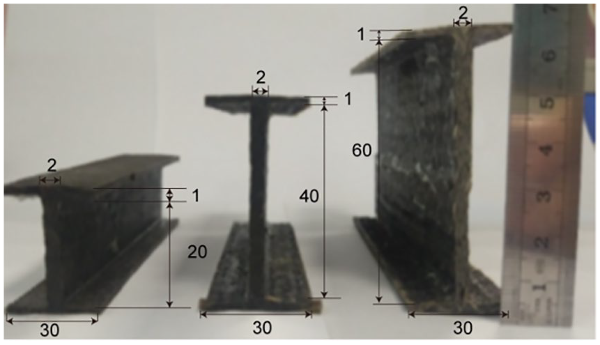
The 3D I-shaped woven composites.
Testing of compression property
The characteristics of the VARTM process were that the top surface of composite was slightly rough and the bottom surface was smooth. In my opinion, the effect of this factor on the compressive behavior was not significant, so it was neglected in this article. The testing standard of compression property was according to GB/T 1448-2005 and the tests were conducted on a microcomputer-controlled electronic universal testing machine (TH-8102S). The testing speed was 10 mm/min. The schematic diagram of compression property test was shown in Figure 7.
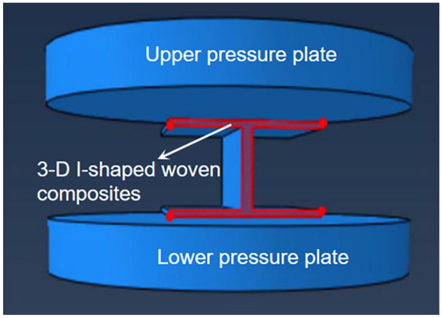
Schematic diagram of compression property test.
Results and discussion
Compression property
The mechanical responses of 3D I-shaped woven composites under compression test were evaluated by load–displacement curves and total energy absorption. The load–displacement curves of 3D I-shaped woven composites with three different heights in experiment were shown in Figure 8(a) (the thickness was 2 mm), and the load–displacement curves of 3D I-shaped woven composites with three different thicknesses in experiment were shown in Figure 8(b) (the height was 20 mm).

Load–displacement curves of 3D I-shaped woven composites: (a) The thickness was 2 mm and (b) The height was 20 mm.
It was seen from Figure 8(a) that the thickness was fixed to 2 mm. When the height was 20 mm, the maximum compression load was 951.43 N. When the height was 40 mm, the maximum compression load was 790.03 N. When the height was 60 mm, the maximum compression load was 428.71 N. And the compression load decreased with the increase in the height of the composites at the same displacement. This indicated that the compressive load was sensitive to the change in height of the composites. The reason was when the height of 3D I-shaped woven composites was lower, the transmit of compressive load was more rapid and uniform, and the 3D I-shaped woven composites with the height of 20 mm were pressured by the whole structure of the composites, which had a larger load. With the increase in the height, the transmit of compression load was slow and nonuniform. Therefore, the 3D I-shaped woven composites with the height of 60 mm were only pressured by the upper layer of the composite, so the compressive load of the composites decreased with the increase in the height.
It was seen from Figure 8(b) that the height was fixed to 20 mm. When the thickness was 2 mm, the maximum compression load was 951.43 N. When the thickness was 4 mm, the maximum compression load was 2137.85 N. When the thickness was 6 mm, the maximum compression load was 3523.24 N. The curve was obviously divided into three stages. In the first stage, the curve tended to rise in a straight line; in the second stage, the curve increased in a small range; and in the third stage, the curve showed a downward trend. The compressive load increased with the increase in the thickness of the composites. Significantly, the thickness of the composites had an advanced effect on the compressive load. This indicated that the compression load was also sensitive to the change in thickness of the composites. The main reason was that the 3D I-shaped woven composites were mainly supported by the middle beam and flange during the loading process. Therefore, the thickness had greatest impact on the performance of the entire composites.
Energy was also an important index to measure the mechanical property of composites. The total energy absorption of 3D I-shaped woven composites under compression was shown in Figure 9. The total energy absorption of 3D I-shaped woven composites with three different heights from experimental was shown in Figure 9(a), and the total energy absorption of 3D I-shaped woven composites with three different thicknesses in experiment was shown in Figure 9(b).

Total energy absorption of 3D I-shaped woven composites: (a) The thickness was 2 mm and (b) The height was 20 mm.
Because of the large enveloped area of load–displacement curve, the capability for energy absorption was very high. It can be seen from Figure 9(a) (the thickness was 2 mm) that as the height of the composite increased, the total energy absorption decreased. And it also can be seen from Figure 9(b) (the height was 20 mm) that as the thickness of the composite material was higher, the total energy absorption was higher.
The mechanical properties of 3D I-shaped woven composites with three different heights and thicknesses were shown in Tables 2 and 3, respectively. The data in Tables 2 and 3 were calculated by the following formula according to the experimental data
Mechanical property of 3D I-shaped woven composites with three different heights.

Mechanical property of 3D I-shaped woven composites with three different thicknesses.

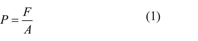

P is the compressive strength (MPa), F is the failure load (N), A is the load area in the compression process (mm2), E is the modulus of elasticity (GPa), ΔF is the load increment of the initial linear part on the load-displacement curve (N), ΔL is the displacement increment corresponding to the load increment of ΔF (mm), and L is the displacement corresponding to the failure load (mm).
It can be seen from Table 2 that the compression performance of the 3D I-shaped woven composites with 20 mm was best and the compression performance of the 3D I-shaped woven composites with 60 mm was worst. The flexural performance of the 3D I-shaped woven composites with 40 mm was medium. It can also be seen from Table 3 that the compression performance of the 3D I-shaped woven composites with 6 mm was best and the compression performance of the 3D I-shaped woven composites with 2 mm was worst. The flexural performance of the 3D I-shaped woven composites with 4 mm was medium. When the height of the 3D I-shaped woven composites was 20 mm and the thickness was 6 mm, the maximum load was 3523.24 N.
On the whole, the compression property of 3D I-shaped woven composites decreased with the increase in height of the composites and increased with the increase in thickness of the composites.
Failure mode and failure mechanism
The results of 3D I-shaped woven composites with different heights were similar. Consequently, only the 3D I-shaped woven composites with the height 60 mm and the thickness 2 mm were used as an example, and their total and partial enlargement photographs were shown in Figure 10(a) and (b), respectively. The results of 3D I-shaped woven composites with different thicknesses were similar. Thus, only the 3D I-shaped woven composites with the thickness 4 mm and the height 20 mm were used as an example, and their total and partial enlargement photographs were shown in Figure 10(c) and (d). Figure 10(a) and (c) were the total failure photographs of the composites, and Figure 10(b) and (d) were the partial enlargement photographs of the composites.
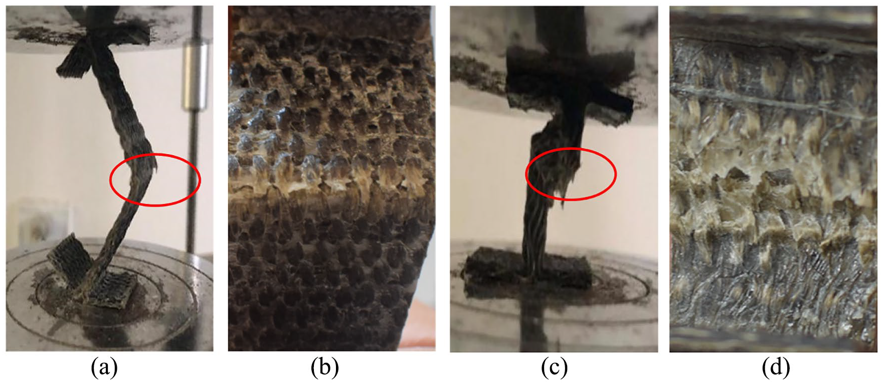
Total and partial enlargement photographs of 3D I-shaped woven composites: (a), (b) The height was 60 mm and the thickness was 2 mm; and (c), (d) The height was 20 mm and the thickness was 4 mm.
In the first stage, when the squeeze head continued to drop and completely contacted the surface of the 3D I-shaped woven composite, the composite was stressed and bent. The compression load increased with the increasing compression displacement. In the second stage, as the texture of each layer of the composite was firmly bonded by the epoxy resin matrix, more and more fibers shared the load. When the compression load reached the maximum value, the composite reached the stress limit, and few fiber fractures occurred. In the third stage, the matrix of the material was completely cracked, some fiber bundles were broken, and shear failure occurred. It can be seen from Figure 10, the compression failure modes had brittle fracture of the fiber bundle, cracking of the matrix, and a typical shear failure in the beam (A2). But, the 3D I-shaped woven composite had a good integrity and there was no delamination. With the increase in compression load and the accumulation of damage, the gradual destruction of the interface between fiber bundles and the matrix was bigger, which finally caused the destruction of bonding surface between the fiber bundles and the matrix. Then, the matrix cannot provided support for the fiber bundles. As the load was further increased, the matrix on the surface of the fiber bundles was completely crushed. Meanwhile, the fiber bundle was subjected to a main compressive load, and the lateral expansion caused the material to gradually become loose and buckling, but the fiber bundles remained substantially intact. Therefore, the 3D I-shaped woven composites had a good integrity and no delamination.
Conclusion
The experimental results show that the 3D I-shaped woven composites with basalt fiber filament tows had good compression performance. When the height of the 3D I-shaped woven composite was 20 mm and the thickness was 6 mm, the maximum load was 3523.24 N. The results show that the compression load of the 3D I-shaped woven composite decreased as the height of the composite material increased, and the thickness of the composite material is also increased. The failure mode of the 3D I-shaped woven composites was mainly brittle fracture of the fiber bundle, cracking of the matrix, and a typical shear failure in the beam (A2). During the test, the 3D I-shaped woven composites had no delamination and splitting and show good total performance.
Footnotes
Declaration of conflicting interests
The author(s) declared no potential conflicts of interest with respect to the research, authorship, and/or publication of this article.
Funding
The author(s) disclosed receipt of the following financial support for the research, authorship, and/or publication of this article: The author(s) gratefully acknowledge financial support from the National Science Foundation of Liaoning Province (2019-MS-017) and the Technological Innovation Team Project of Liaoning Province (LT2017017).