
Abstract
A hardware and software platform is presented enabling the design, and realisation via printing, of smart fabrics. The cultural and creative industries are an important economic area within which designers frequently utilise fabrics. Smart fabrics offer further creative opportunities to the cultural and creative industries, but designers often lack the required specialist knowledge, in electronics, software and materials, to produce smart fabrics. The software platform offers the ability to perform design, layout and visualisation of a smart fabric using a library of standard smart fabric functions (e.g. electroluminescence) so specialist expertise is not needed. Operation of the smart fabric can be simulated, and parameters can be set for smart fabric control electronics, which consists of standard circuit board modules. The software also provides driver code for the hardware platform to print the smart fabric. The hardware platform consists of a bespoke dispenser printer; functional inks are deposited via a pneumatic syringe controlled by the driver software, allowing bespoke rapid prototyped smart fabrics to be printed. Operation of the software and hardware system is demonstrated by the realisation of an interactive smart fabric consisting of electroluminescent lamps controlled by a proximity sensor. The modular electronics are used to control the smart fabric operation using embedded code generated by the software platform. For example, the blink rate of the electroluminescent lamp can be adjusted by the proximity of a hand. This control is achieved by the use of intuitive drop-down menus and input/output selections by the creative user. At present, the platform allows the design, print and implementation of smart fabrics incorporating the functions of colour change, electroluminescence, sound emission and proximity sensing. The platform can be expanded to add additional functions in the future and the printer will be compatible with new inks developed for screen and inkjet printing.
Introduction
Smart fabrics (or textiles) are conventional fabrics incorporating electronic functionality for sensing, actuation or appearance enhancement. Smart fabrics find applications wherever fabrics are used, such as in healthcare, consumer products or vehicles. Fabrics are widespread in the cultural and creative industries (CCI) as a medium through which to express creativity such as, for example, in fashion, the arts, interior design, for advertising banners or for architectural canopies. However, the fabrics used are predominantly low-added-value items to which creative input is added by means of their structural form or through the addition of standard coloured inks or paint.
In 2017, the CCI generated £101.5 billion a year for the UK economy which is £11.5 million an hour. 1 The CCI are defined as follows: 2 ‘Those industries which have their origin in individual creativity, skill and talent and which have a potential for wealth and job creation through the generation and exploitation of intellectual property’. The CCI are generally considered to cover the following areas: 3 advertising, architecture, design, designer fashion, software, computer games, electronic publishing, arts, visual/performing arts, crafts, cultural tourism and heritage; film, video and photography; and music, publishing, television and radio.
The CCI therefore represent a significant potential area of application of smart fabrics. By incorporating electronic functions, the fabric is transformed to a high-added-value item offering additional creative options to designers. Smart fabrics offer new possibilities to create interactive designs and artworks in any creative industry sector using fabrics. Typically, smart functionality is incorporated in the fabric by weaving, knitting or embroidering special electrically functional yarns (e.g. conductive yarns) or attaching discrete electronics. However, electronic functional inks, where the printable ink contains additional functional particles (e.g. conductive, dielectric or electroluminescent), allow smart functionality to be printed on a fabric like a standard coloured T-shirt print. Printing provides the creative designer with greater design freedom, compared to the alternative techniques, and enables production of the smart fabric using a local or shared remote printer.
However, the design and realisation of a printed smart fabric requires specialist and sophisticated electronics, software and materials knowledge. This presents a major barrier to the uptake of smart fabrics within the CCI within which expertise is focused on design creativity with limited or no electronics, software and materials knowledge. This article presents a software and hardware platform technology which allows the CCI to design and realise smart fabrics with no specialist expertise in electronics design, software implementation or printed electronic materials. For the first time, the CCI can design smart fabrics using a software suite and automatically realise bespoke smart fabrics by printing using a remote printer. Devices are printed layer by layer using a bespoke direct write printer; each functional layer is cured after printing using ultraviolet (UV) light or infrared. This breakthrough, which removes a major barrier to the wider exploitation of smart fabrics, is achieved through advances in smart fabric functional printing hardware, inks and software.
Section ‘State of the art’ of this article describes the state of the art in the application of printing to the realisation of smart fabrics. Section ‘Software design suite’ describes the software design suite consisting of the design tool, the translation tool and the visualisation tool. Section ‘Hardware platform: dispenser printer’ describes the hardware platform which is a bespoke digital dispenser printer allowing smart fabrics to be directly printed from the software. Section ‘Hardware platform: electronics’ describes the modular electronics used to control the smart fabric which is programmed from the software. Section ‘Smart fabric realisation: example design and printing of electroluminescent lamps coupled to a proximity sensor’ describes an example smart fabric created using the platform consisting of a proximity sensor and two electroluminescent lamps. Finally, conclusions are given in section ‘Conclusion’.
State of the art
Three printing techniques have primarily been applied for the realisation of smart fabrics: screen printing, 4 inkjet printing 5 and dispenser printing (DP). 6 Screen printing uses physical screens to define the geometry of each layer before printing to make a device. Each printed electronic functional ink requires an individual screen, and therefore as each printed electronic device increases in complexity or functionality the number of costly screens required is increased. It is therefore suited to large production runs of a finalised device design but not to the one-off bespoke designs or small-scale rapid prototype production required by the CCI.
Inkjet printing offers a solution to this in that no screens are required and only the computer image of each layer is needed to define the final design. However, the cured thickness of a material deposited by an inkjet printer is typically <1 μm which cannot overcome the typical surface roughness of a fabric when attempting to print the continuous electronic layers needed in functional smart fabrics. For example, a typical polyester cotton fabric has a surface roughness of ~31 μm7 with the loose fibres created in the manufacturing and handling process making overall surface roughness >50 μm.
DP, like inkjet printing, also prints directly from the computer design, but the cured thickness of printed layers is similar to that of screen printing, therefore allowing the achievement of continuous electronic layers on rough fabrics. DP has been successfully used on fabrics for conduction on non-woven fabrics 8 at the US National Textile Research Center. Berkeley University have dispenser printed onto a flexible polyimide substrate creating a thermoelectric generator, 9 lithium-ion batteries and an electrochemical capacitor 10 and a zinc ink deposited on silicon provided the proof mass in an accelerometer. 11 Dispenser printed smart fabrics have also been demonstrated for the functions of sound emission, 12 electroluminescence, 13 colour change,14,15 stretch sensing 16 and proximity sensing. 17 However, each of these demonstrators was printed as single devices with individually programmed printer paths for each layer – this is unsuitable for the targeted creative industry users because of the complexity involved and the specific printing knowledge required. This article presents a universal hardware and software platform dedicated to the design and realisation of smart fabrics for the creative industry. An example printed interactive smart fabric is designed using the dedicated functional library embedded within the software and printed using the hardware platform.
There is currently no other example in the literature or industry which can achieve this link between the CCI user and the final printed smart fabric in this intuitive and embedded platform methodology.
Software design suite
The primary purpose of the software design suite is to enable the CCI to use the creative software tools that they would normally use, such as Adobe Illustrator (AI), but provide additional functionality to allow the creation of smart fabrics such as interactive artworks. The software design suite consists of three key elements:
The ‘Design Tool’ enables designers to create colour images and add smart functional elements for light emission, colour change, sound emission and proximity/touch sensing.
The ‘Translation Tool’ converts the design into the printed layers needed for smart fabric realisation using conventional inkjet colour inks and electronically functional inks for the smart functions.
The ‘Visualisation Tool’ allows the user to see/adjust the appearance and functionality of the final smart fabric before printing. Parameters can be set to control the smart fabric’s functions such as electroluminescent lamp brightness, proximity sensor range and colour change response. These parameters are then embedded within the modular control electronics.
Currently, the software suite allows the creative user to add four electronic functions to their designs. These are a proximity sensor, an electroluminescent lamp, a thermochromic display and a loudspeaker. These design elements provide interactivity via proximity and touch, light emission, colour change and sound emission.
Design tool
The ‘Design Tool’ enables designers to create colour images and add smart functional elements for the functions of light emission, colour change, sound emission and proximity/touch sensing. The current software uses an add-on for AI which allows the conversion of drawn elements into electrically functional elements. For example, the designer can draw an enclosed polygon of any shape using the normal polygon creation tool, select it and use the design tool add-on to convert it into the required function. The software then allocates a place holder status to this section of the image file so that, when it is exported via the translation tool, these data can be converted into printing layers. In addition, there are a number of library files using standard shapes (circles, squares, rectangles) which can also be added onto the non-functional coloured background image. In this way, the designer can create the interactive designs without requiring a deeper understanding of the printed layer technology behind them. Figure 1 shows an example of the design software being used in AI.

Example drawing and functional elements used in the design tool via the design tool add-on for Adobe Illustrator. The square represents the proximity or touch sensor. The circles represent the electroluminescent lamps.
Currently, the add-on works with AI which was chosen because of its widespread use in the CCI. However, the files are saved as a Scalable Vector Graphics (SVG) file which can then be imported into the translation tool or shared with other users to edit directly. Existing designs in the translation tool library can also be downloaded back to the design tool for further editing. The SVG file format was chosen because it can be easily read in modern Internet browsers and is compatible with most advanced drawing packages.
Translation tool
The ‘Translation Tool’ converts the user-generated design into the required printed layers necessary to realise the smart fabric using conventional inkjet colour inks and electronic functional inks for the smart functions. The translation tool is built using the system architecture shown in Figure 2.

System architecture of the translation tool.
The ‘Design Tool’ is used to export the data into the ‘Translation Tool’ which is built into the Google Chrome Internet browser. Chrome was chosen because it is able to use SVG files and allows multiple users to collaborate together in real time on the design. As shown in Figure 2, the image file, imported from AI, is converted so that the standard passive artwork becomes the background of the smart design and the chosen ‘placeholder’ elements are converted to their respective devices and associated layers. There are seven layers available to use: the fabric interface, conductor, thermoelectric, dielectric, phosphor, transparent conductor and encapsulation layers.
Figure 3 shows the design tool graphical user interface (GUI) and the example design imported into the translation tool before the auto-routing tool is used.

Design tool GUI and example imported from Adobe Illustrator before auto-routing.
The left-hand side of the GUI has the menus for adding library designs for each of the printed elements as well as editing tools for modifying the size and shape of the active elements and to modify the wiring after the auto-route is complete. The right-hand side has three menus to edit the following:
Functionality defines the connections, auto-routing and element names;
Visualisation board is used to allow the user to observe the functionality via interactive animations;
Operator board is used to define the material properties for each layer and set the resolution of printed lines.
In this example, to allow connection to the external drive electronics, a four-pin connector is added to the design. The connector element is obtained from the library files within the software and placed on the border of the design. At this stage, any final positioning or size adjustment of the active elements can take place. Once finalised, the next stage is to activate the routing tool which automatically joins up the different control pins of the active elements and routes the wire pathway to the corresponding connector pin. The wire pathway can be manipulated to avoid any overlaps, potential routing problems with wires being too close or just to improve the aesthetic of the final design. The line routing uses an open-source routing JavaScript 18 which uses the A* pathway generation algorithm.
A* is a line search algorithm which uses less computing power compared with a grid search algorithm. A* uses the function f(x) = g(x) + h(x) to evaluate the cost of a path x, where g(x) is the cost from the source node to the current node of x and h(x) is the estimated (or predicted) cost from the current node of x to the target node. Every time the algorithm selects a node with the lowest path cost to propagate (i.e. the lower f(x)), the priority for propagation is higher. As a result, the A* search is also called the ‘best-first search’, because at each decision it first searches the routes that are most likely to lead towards the target. Generally, the best-first search is a special case of the A*-search algorithm, where h(x) = 0 for all x. Figure 4 shows the first result from the auto-routing tool and subsequent improvements in the layout aesthetic.

Example output of auto-routing function: (a) original result and (b) modified design for improved aesthetic. The blue and green lines represent the interconnecting conductors with 3 connection points shown on the left in purple.
The final stage for the design tool is to generate the printed layers and printing code ready to send to the printer. When generating these layers, the software performs a design rule check to ensure that the routing is correct and the placement of the elements is in accordance with predefined design rules. The rules engine is a JavaScript API (Application Programming Interface) which validates the design and generates an interactive error report. Each error identifies the involved elements. A user interface exists that visually marks the wrong items when an error is selected. Only when these errors are cleared will the printer pathway code be accessible, and thus the visualisation tool. The printer pathway is generated using a coordinate and control language known as G-code, which is based on the RS-274 standard. G-code is used extensively throughout the computer numeric control (CNC) industry for machine tools. G-code provides linear interpolation movement coordinates for the three movement stages, stage speed, tool selection (in this case selecting between the printing and curing sides of the head) and differentiates between a printing move and a non-printing move as the printhead traverses across the substrate.
Visualisation tool
The ‘Visualisation Tool’ allows the user to see and adjust a visual representation of the appearance of the final smart fabric before printing. This tool avoids wasting of printing time and materials because design iterations can be performed before printing as well as demonstrations to collaborators and customers. Parameters can also be set to control the smart fabric’s functions such as electroluminescent lamp brightness, proximity sensor control distance, activation speed of the thermochromic layer and sound emission levels. The interdependency of each element can be set using the controls; for example, one electroluminescent lamp may flash continuously, while the other electroluminescent lamp is controlled by the proximity sensor. This simple form of programming is based on drop-down menus and is very intuitive, selecting each component in turn and what its function and response is, forming a ‘pseudo-code’ which can be run in the visualisation tool.
The electroluminescent lamps are shown in the visualisation tool via a simple colour change, while the proximity sensor is represented by a line controlled by the movement of a mouse with a distance percentage graphical indicator. If the mouse moves towards the proximity sensor graphic, then the percentage reduces until 0% when it displays ‘Touch’ with 100% being the maximum detectable range with above this being set to ‘Away’. An example of the visualisation tool with proximity sensor control is shown in Figure 5.

Example of visualisation tool functionality with proximity control simulation via a mouse – touch switches both lamps on: (a) ‘Away’ indicates a hand is not within the detection range of the proximity sensor and (b) ‘Touch’ indicates a hand is within the range of the proximity sensor or touching it.
Once the design is complete, the printer pathway G-code can be generated and sent to the printer for printing. The pseudo-code, created by the designer to define the interactivity and performance of the individual elements, is subsequently converted to Arduino code for use with the modular electronics. The code can be used directly from the visualisation tool or it can be edited manually by experienced end users.
Hardware platform: dispenser printer
Electronic inks can be produced using functional electronic particles which can be at either the nanoscale or the microscale. Nanoparticles are particles between 1 and 100 nm in size with a surrounding interfacial layer. Microparticles are 1000 times larger. Functional particles form the basis of electronic functional inks by combining them with chemicals such as surfactants, anti-foamers, binders, solvents and catalysts. Electronic functional inks can be printed on the fabric using techniques which are already used in the CCI (screen and inkjet) as well as the direct write dispenser printer used for this research. DP uses a pneumatic system attached to a syringe loaded with the printable ink, shown in Figure 6, allowing the design to be printed directly from the software.

Schematic of direct write pneumatic dispenser printing.
The syringe is held above the surface of the fabric by a Z stage suspended via a gantry above a set of XY stages driven by NEMA23 stepper motors with integrated encoders attached to ball screws giving a positional accuracy of 0.05 mm in the X and Y directions and 0.005 mm in the Z direction. Each stage can be driven with maximum speeds of 50 mm/s, but these are typically reduced to 10–15 mm/s to improve the stability of the platen during printing. The printer platen is 500 × 500 mm2, but due to the size of the printhead the practical printing area is currently reduced to 365 × 420 mm2 in X and Y, respectively. The full dispenser printer system is shown in Figure 7.

Dispenser printer setup showing the printing syringe with XYZ stages and printer platen along with the UV curing system.
The printer driver software has been written using National Instruments LabVIEW to control the Arcus Technology PMX-4EX-SA-TBS four-axis motor controller which drives the stages and the Nordson Ultimus V pneumatic dispenser which controls the dispensing syringe. The printing height is determined by a nozzle zeroing process which brings the tip of the dispenser gently into contact with the fabric surface, and it is then backed away to match the printing parameters for the particular ink being printed, typically between 100 and 250 µm.
After each layer is printed, either the sample is removed for infrared curing of the ink in a standard box oven or the attached Omnicore 450 UV lamp, shown in Figure 7, is used to cure the ink in situ. The UV lamp is attached to the side of the printed head and, when required, is passed above the printed ink at a specific distance and intensity suitable for the printed ink. The intensity of the lamp is sufficient to completely cure the ink in one pass before moving back to the origin to begin printing the next layer. The movement pathway for this curing process is determined by the CREATIF software automatically, using the same process as the printed electronic functional ink layer. Once all the layers have been printed, the device is ready for connection to the electronics for operation via the printed connector.
Hardware platform: electronics
The electronic circuit is designed to allow both simple and more complex printed designs without becoming too large or complex itself. The overall electronics have been designed to be modular; thus, it can be modified by connecting or removing functional modules where required by the smart fabric design. The Arduino platform has been selected for use as the microprocessor because a range of Arduino microcontrollers are already widely accepted and used in the CCI and are well supported by the creative maker community. The Arduino Due is selected as it has a 32-bit ARM core microcontroller to allow for significant complexity and provides 54 digital input/output pins and 12 analogue inputs allowing the integration and control of the necessary electronic functional modules for each printable function (e.g. electroluminescence). The Arduino Due can also be expanded in the future through the use of additional boards to add further functionality, such as wireless communication.
The concept of the electronics is to maximise the flexibility, scalability and reliability and minimise cost from the designer’s point of view. The overall system is therefore designed using a modular approach as shown in Figure 8.

An illustration of the modular hardware design.
The central control and processing is achieved using the Arduino Due microprocessor board. This is coupled with a separate printed circuit board (PCB) to control and drive the functional modules, known as a shield. To add further control and drive capability, additional PCBs can be stacked on top of the Arduino. Each of the smart fabric functions (e.g. sound emission) is controlled using a specific functional module. Figure 9 shows the currently available electronic functional modules. These modules can be duplicated as necessary to increase the number of smart fabric functions. This approach permits the design of the controller to be subsequently modified by adding and subtracting modules from the design as required allowing new functions to be integrated.

Functional modules available to achieve smart fabric functions: (a) proximity/touch sensing module, (b) electroluminescent light emission module, (c) spiral speaker audio emission module and (d) thermochromic colour change module.
Each functional module has a standard functionality providing the designer with the flexibility to design with a choice of different functions on the smart fabric while using a single hardware platform. The submodules in Figure 9 offer the following functionality:
Proximity/touch sensing module. This is achieved using a proximity sensor integrated circuit which provides a single proximity sensor channel and its associated guard electrode which is used to reduce the effects of parasitic capacitance and thus improve sensitivity and range.
Electroluminescent light emission module. This module applies an AC voltage to the printed lamps. The lamps are individually controlled with adjustable brightness from 0% to 100% of the full brightness.
Spiral speaker sound emission module. The volume level of the audio drive signal for the spiral speaker can be set using a digital potentiometer from 0% to 100%. An off-board power module provides the required drive levels for the spiral speaker and an audio source is provided by an external source, typically an MP3 player.
Thermochromic colour change module. The colour change is achieved using printed heater elements located underneath or around a thermochromic material. As the heater elements are heated, they cause the thermochromic ink to change temperature and its colour changes from black to transparent, thus changing the aesthetic of the smart fabric. The heaters are implemented as resistive heaters and their supply current is regulated via a constant current source with pulse width–modulated drive functionality to enable the average current to be set, thus altering the heating rate as desired.
To make efficient use of the available interconnections to the Arduino Due, the functionality of the modules is controlled using a serial bus using the I2C serial interface. This modularity enhances the sustainability of the smart fabric electronics by allowing the same modules to be used interchangeably between designs. Therefore, when one installation is no longer required, the electronics can be reused and reconfigured for a new installation. In addition, should the installation suffer damage or be surplus, the electronics can be retained for future use in future designs, swapping out functionality as required.
Smart fabric realisation: example design and printing of electroluminescent lamps coupled to a proximity sensor
This section provides an example of the software design and subsequent printing process. This is illustrative of the process for any design using this software and printing system and uses each stage of the process. Figure 10 shows the typical design flow and decision tree when using the software tools to create an interactive smart textile.

Workflow for creating interactive smart textiles using the design and visualisation tools before printing.
Figure 10 shows three designers collaborating on a smart fabric design. One designer begins the process with a normal drawing in AI, using the design tool plugin to add smart element placeholders to the drawing. This can then be shared via a cloud system with the other designers to collaborate and downloaded back to AI for editing or collaboratively edited in the cloud design tool. Once the design is complete, the translation tool is used to create the printed layers and the design rules are checked. If the design rules fail, then further collaboration between designers can improve the design until it passes the rules and the visualisation tool can be used to simulate the design. If the design is complete, then it is ready to be converted into G-code for the print driver and then printed by the printer, with either a local printer or a remote printing service, similar to the three-dimensional (3D) printing business model.
Software design
To demonstrate the platform, an initial background image of 150 × 150 mm2 was created in AI using the standard process for any non-functional image drawing. Subsequently, using the design tool add-on, three library elements were added to the design: a small electroluminescent lamp, a medium electroluminescent lamp and a proximity sensor. Having positioned these elements onto the canvas, the design was exported to the translation tool in the Google Chrome web browser. The design tool in Chrome was then used to show the individual elements and the background image for inkjet printing. A four-pin connector was added to the design and lamp and proximity sensor connections were defined before the device interconnections were generated using the routing tool. The generated interconnections were manipulated to avoid any design rule failures and to improve the aesthetic of the final design. Once the design rule check was complete, the layers and the printing pathway were generated for use in the printer driver. An example of the printer pathway G-code generated for each layer of the design is shown in Figure 11.

Example of printer pathway code for each of the layers in the design.
Figure 11 shows the encapsulation layer highlighted, the red lines are where it will print the material and the green lines are where the printer head lifts away from the substrate to move to another part of the design. The line spacing and number of passes of the printhead are controlled via the recipes for the individual layers.
To improve the print quality, three printing passes are printed for the conductive tracks and these are separated by 0.3 mm which is the minimum resolution that Chrome can provide. It is possible to print only a single line, but if there are any defects during the print, such as an air bubble or agglomerate in the paste, then the track will fail. Three passes improve the yield because the second or third printing pass can fill any track defect. In this case, the printer will print from point A to point B along the desired pathway, then back to A, then back to B, creating a total of three print pathways separated by 0.3 mm which is sufficiently close that the printed ink will flow together to form one path between A and B.
The same principle is applied to all the printed elements whereby the line spacing is defined as 0.3 or 0.6 mm to ensure that the printed lines are sufficiently close that the ink can settle and form a homogeneous layer. If the printed lines were closer, then there is a greater risk of the nozzle touching the wet ink or the printed layer being too thick and be prone to cracking during the curing process. The printer pathway code is then exported to the printer driver to print the devices on the fabric. The LabVIEW program converts this G-code into a bespoke program for the printer controller.
Printing
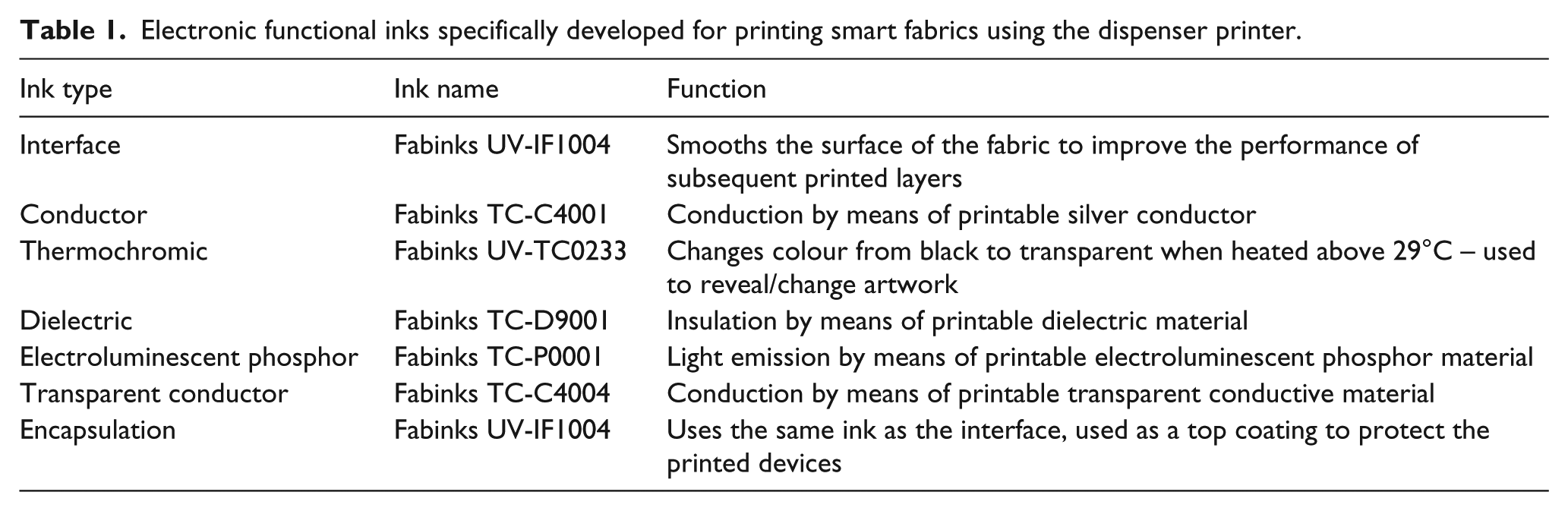
The smart fabric functions are realised by printing the electronic functional ink directly using the DP platform 19 onto a 100% polyester woven fabric with a polyvinyl chloride (PVC) coating (FRONTLIT II standard FR) supplied by Mehler, Germany. This fabric is one of the most common fabrics used in the CCI and is the base material for display banners, exhibition stands and window blinds. A family of electronic functional inks have been specifically customised for fabrics and available inks include interface, conductive, thermochromic, dielectric, phosphor (electroluminescent), transparent conductor and encapsulation, as shown in Table 1. However, the printer can deposit any screen or inkjet printable ink by changing the nozzle size and printing pressure to match the viscosity of the ink.
Electronic functional inks specifically developed for printing smart fabrics using the dispenser printer.
The printing process is controlled by a bespoke LabVIEW program which controls the printing parameters, such as stage speed (printing and not printing) and nozzle separation height. Figure 12 shows the GUI of a LabVIEW control program used to print the smart fabric demonstrator.

Graphical user interface (GUI) of LabVIEW printing setup (orange: x/y/z movement control; blue: print speed control).
This LabVIEW control program allows each layer of smart fabric devices to be printed and cured in real time, thereby minimising the need of intervention during the entire printing process. An additional profiling function enables the surface of the substrate to be measured such that the desired printing gap between the substrate and nozzle is maintained during the entire printing process. This is particularly important since a consistent printing gap provides a uniform and even layer thickness, thus reducing the chance of short circuits and maximising the transparency of the top electrode which is essential for the electroluminescent lamp.
The substrate is prepared by temporarily attaching the fabric onto an alumina tile to provide stability during printing. This tile is then positioned against the alignment corner on the printer plate and held in place by magnets. The printing process starts by initialising all three stages to the zero positions and then loading the printing file generated from the translation tool.
The syringe with the desired ink is manually loaded onto the holder on the printer head and the nozzle distance is adjusted to achieve an optimised printing gap. If the nozzle is too close to the surface, then the ink will be too thin and there is potential for the nozzle to drag the ink as it passes over the previously printed line. If the nozzle is too high, then the ink will not touch the substrate when it is initially dispensed and there will be a build-up of ink before it eventually drops to the substrate, thus the print will be of poor quality.
The printing pressure controls the flow of the printed ink during printing; the higher the viscosity of the ink, the more the pressure that is required to dispense a suitable volume. When the nozzle is moving between printed sections, there must be a back pressure on the ink to prevent it dripping due to gravity, and this is provided by the vacuum setting. The two printing parameters are derived via prior knowledge of the printing process and short printing trials consisting of printing repeated lines with different sets of parameters and identifying the optimum print quality.
The type of ink being printed also influences the line spacing required. The line spacing is the distance between each printed line which produces the final printed layer. The printed inks are thixotropic and will therefore relax slightly after printing allowing the individual lines to merge together to form a more homogeneous film. If the lines are too close together, then this results in a thicker print which is a waste of material and excessive ink deposits can lead to ‘bleeding’ where the ink spreads beyond the intended pattern. If the lines are too far apart, then they will not flow together properly after printing and thus the printed layer will be non-homogeneous and in extreme cases will not function as intended, for example, a conductive track will have breaks in it making it open circuit.
The demonstrator shown in this article includes one proximity sensor and two electroluminescent lamps. They were printed onto the Mehler fabric which is sufficiently smooth and it does not require the interface layer; therefore, four layers in total are printed. Each layer is printed with a specific set of parameters to maximise the printing quality and the details are shown in Table 2.
Printing and curing parameters of conductive layer.

For this particular demonstrator, each of the printed inks is thermally curable, and therefore once the layer was printed it was subsequently cured in a Carbolite AX30 convection oven at 125°C for 10 min. Once the curing is finished, the substrate is then repositioned to the original alignment corner on the printer, the next printing material is selected and the subsequent printed layer is printed on top. This printing/curing process is repeated on every printed layer until the design is complete.
Printing results
Figure 13 shows the complete printed smart textile as a demonstrator of the complete design process, from initial AI passive in design to printed functional smart fabric device.

Printed demonstrator showing two electroluminescent lamps and one proximity sensor with associated connector at the edge of the fabric; electroluminescent lamps in the off state.
The results show that the printed design matches the electronic design. There are some minor alignment defects for the large lamp compared to the small lamp; this is due to the positional errors caused (<1 mm) when removing and replacing the substrate on the printer platen. The transparent top electrode layer has printed slightly thicker than an ideal print which can be identified by the darker blue colour. The top electrode material is challenging to print due to the high surface tension of the ink compared with the other materials. This was mitigated in some way by choosing a higher line spacing (0.6 mm) and a reduced nozzle gap (120 µm). This could be further improved by reducing the printing pressure, but if the pressure is too low then the surface tension of the ink does not break consistently and the print quality becomes uneven. It can be seen that the silver conductor path has printed well, with only the bottom part of the proximity sensor being printed slightly thinner (~5 µm compared with ~10 µm for the other sections). This can be due to variations in the substrate thickness, either directly in the fabric or indirectly from how it is adhered to the substrate holder during printing.
The printed devices are connected to the modular electronics which are programmed via the software visualisation tool. The visualisation tool was used to allocate a function to each element; in this case, the proximity sensor is assigned the operation of a proximity sensor (rather than touch sensor); the lamps are set to flash once per second until a hand is detected in a 2-cm range which will then move the lamps to a state where they are always on. When the proximity is released, the lamps will return to flashing every second. Figure 14 shows the electroluminescent lamps lit up when activated by the proximity sensor (i.e. when a proximity of 2 cm is detected).

Demonstrator with electroluminescent lamps switched on by proximity sensor detection via the CREATIF electronics.
The results show that the designs can be converted from drawings into printed devices correctly and that the visualisation tool can be used to program the electronics to provide different functionality of the fabric depending on the desired application.
This demonstrator shows the proximity sensor and electroluminescent lamps, but the same process occurs for the printed speaker, 12 which uses the conductor and dielectric layers, and the printed thermochromic display, 15 which uses the conductor and thermochromic layers.
Conclusion
A software and hardware platform to design and realise smart fabrics has been achieved. The platform targets the CCI and the software allows the design, layout, visualisation and simulation of a smart fabric. The design is then printed using the hardware platform which is a bespoke dispenser printer directly driven by the software platform. The functionalisation of existing conventional fabrics is therefore undertaken by printing active electronic materials in the form of electronic functional inks/pastes. Modular electronics based around an Arduino Due is used to control the smart fabric operation using embedded code generated by, and set up and simulated within, the software platform. The platform has been demonstrated by the design and printing of an interactive smart fabric incorporating a proximity sensor coupled to electroluminescent lamps.
The hardware/software platform can produce smart fabrics for light emission, colour change and sound emission, touch and proximity sensing. The platform enables non-experts to design smart fabrics removing the barriers to entry to this field by reducing the complexity of the process and the technological learning curve. The platform is compatible with existing design packages used by the CCI (e.g. AI).
DP achieves a printed layer thickness which is more compatible with fabrics than that of inkjet printing and, unlike screen printing, does not require a screen to define each device layer’s geometry. A printer has been designed for smart fabric printing with a 500 × 500 mm2 platen allowing a print area of currently 365 × 420 mm2. Ink deposition is controlled via a syringe on XYZ stages allowing movement in three dimensions. Curing is achieved by infrared or UV light curing depending on the ink.
For the software platform, the SVG files provide a suitable format to allow import/export of designs between design packages and collaborative design can be achieved by importing them to Google Chrome. Up to seven printable layers (fabric interface, conductor, thermochromic, dielectric, phosphor, transparent electrode and encapsulation layers) can be combined to realise four different functions on the fabric and these functions can be further combined with standard colour images. The device interconnection and printable layers are automatically generated using algorithms within the software. G-code is used to control the printer and is automatically generated by the software from the design. The visualisation tool allows the design to be refined and checked to improve its aesthetics, to reduce wasted printouts and to allow the parameters of the functional devices to be set (e.g. lamp blink rate).
Scalable modular electronics have been designed consisting of an Arduino Due microprocessor for control coupled with a separate PCB to drive the functional modules for each smart fabric function. Further control and drive capability is added by stacking additional PCBs on top of the Arduino. The functionality of the modules is controlled using a serial bus using the I2C serial interface.
The overall platform is expandable in each of the individual areas (software, hardware, inks and electronics) in the future to incorporate further functions from the creative industries and new inks developed by the printed electronics industry. The modularity of each component means that it is relatively easy to introduce new designs and functions into the software and new printing recipes for new inks as they become available. The long-term goal for the software is for creative users to develop new library files which they can then share in the community, using the existing functions but also expanding to new functions when they are introduced.
Footnotes
Acknowledgements
We acknowledge the support of the other partners in the CREATIF project.
Declaration of conflicting interests
The author(s) declared the following potential conflicts of interest with respect to the research, authorship, and/or publication of this article: Drs J.T. and R.T. are co-founders of Smart Fabric Inks Ltd.
Funding
The author(s) disclosed receipt of the following financial support for the research, authorship, and/or publication of this article: Authors acknowledge the receipt of funding from the European Union’s Seventh Framework Programme for Research, Technological Development and Demonstration under grant agreement no. CP-FP-INFSO-FP7-610414 for the FP7 project CREATIF: Digital creative tools for digital printing of smart fabrics (![]() ).
).